Ministry of Higher Education and Scientific Research
University of Echahid Hamma Lakhdar El-Oued
Faculty of Technology
Master
’s Thesis
Submitted in Partial Fulfillment of the Requirements for the Degree of
ACADEMIC MASTER
Domain: Science and Technology Specialty: Telecommunication Systems
Theme
Submitted by : Ad Meriem Board of Examiners Dr. LAIB Ismail Dr. . KHELIL Abdellatif Dr. CHAMSA Ali Dr. AJGOU Riadh MCB MCB MCA MCA Chairman Examiner Examiner SupervisorAcademic Year : 2018/2019
Study and simulation of Sparse Code
Multiple Access (SCMA) for 5G New
Acknowledgements
To reach the end of this particular journey would not have been possible without a divine
intervention, I praise ALLAH as many as he has created, as large as the expansion of his
realm, and as heavy as the weight of his throne, and as varied His blessings have been.
I want to express my sincere appreciation to Dr. KHELIL Abdellatif
and Dr. LAIB Ismail
for help me.
Thank you both for the noble attitude with me when I was in a difficult situation.
Dedication
This work is dedicated :
To my parents for their continuous prayers, encouragement, patience and
Love.
To the strongest person I know: Me .
To my sisters 'Sara’, 'Asma' for their encouragement and support.
To my family and friends who encouraged me and prayed for me
Throughout the time of my research.
To all who in one way or another contributed
Table of Contents
Table of Contents……… List of Figures………... List of Tables………. Abbreviations………. General Introduction ………...Chapter 1 An Overview on 5G Technology
1.1 Introduction ……… 1.2 Definition……… 1.3 The difference between 4G and 5G technology………. 1.4 5G technologies………... 1.5 5G Architecture……….. 1.6 5G Standards Bodies……….. 1.7 Categories services Of 5G……… 1.8 Characteristics 5G………. 1.9 The disadvantages of 5G………... 1.10 Conclusion………...
Chapter 2 Access Techniques Using NOMA Technology
2.1 Introduction……… 2.2 Multiple Access………. 2.3 Orthogonal Multiple Access (OMA) Schemes………. 2.4 Non-orthogonal multiple access (NOMA)………. 2.5 Dominant NOMA solutions……….. 2.6 Basic principles of NOMA………. 2.7 Key Technologies of NOMA………. 2.8 Advantages………. 2.9 Disadvantages………. 2.10 Applications……….. 2.12 Conclusion……… I III V VI 1 2 2 2 3 6 7 8 11 13 13 14 14 14 16 16 19 20 21 21 22 23
Chapter 3 Sparse Code Multiple Access (SCMA) Overview 3.1 Introduction………. 3.2 System model……….. 3.2.1 Channel encoding……….. 3.2.2 SCMA encoding……… 3.2.3 PRE Mapping……… 3.2.3.1 Scrambling……….. 3.2.3.2 Modulation Techniques……….. 3.2.3.3 DeModulation Reference Signal……… 3.2.3.4 Layer Mapper………. 3.2.3.5 Resource Element Mapper……….
3.2.3.6 waveform signal Generation………..
3.2.3.7 The additive blocks………
3.2.4 Channel………...
3.2.5 SCMA Decoding……….
3.2.5.1 SCMA detection scheme MPA………..
3.2.6 Chanel decoding………
3.3 Application Scenarios for 5G Networks……….……. 3.4 Challenges and Future Works……….……. 3.5 The characteristics of SCMA………..
3.4 Conclusion………..….
Chapter 4 Simulation and Results
4.1 Introduction……….…… 4.2 Simulation model……….… 4.3 Simulation parameters………..… 4.4 Performance of SCMA modulation with and without turbo code ………..… 4.5 SCMA evaluation performance with Turbo code using SPA algorithm ………. 4.6 SCMA evaluation performance with Turbo code using MPA algorithm………. 4.7 Comparison between SPA and MPA ………..… 4.8 Computational complexity of different SCMA demodulation algorithms………... 4.9 Conclusion………... General Conclusion………... Bibliography………... 24 24 24 25 26 27 27 35 36 40 44 46 49 49 50 51 52 53 54 54 55 55 55 56 57 59 61 62 63 64 65
List of Figures
Fig 1.1 : D2D and Cellular communications share the same radio resources………... Fig 1.2 : Functional architecture for 5G mobile networks……….……... Fig 2.1 : TDMA ,FDMA and CDMA ………..………...
Fig 2.2 : OFDMA and SC-FDMA………..…….
Fig 2.3 : Possible NOMA Solution……….…….. Fig 2.4 : Downlink NOMA in a single cell with one BS and two users………….……….. Fig 2.5 : An example of SC encoding ……….. Fig 3.1 : SCMA uplink chain with channel coding……….. Fig 3.2 : Original SCMA system model with channel coding……….. Fig 3.3 : The principle block diagram of PRE Mapping……….. Fig 3.4 : Signal constellation for QPSK Modulation……… Fig 3.5 : Signal constellation for 16-QAM Modulation………... Fig 3.6 : Signal Constellation for Layered Modulation with QPSK Base Layer and a QPSK Enhancement Layer………... Fig 3.7 : Signal constellation for Layered Modulation with a 16-QAM Base Layer and a QPSK Enhancement Layer………... Fig 3.8 : The structure of Turbo TCM……….. Fig 3.9 : Shuffling construction of the mother constellation……….... Fig 3.10 : An example of shuffling construction of two-dimensional 16-ary SCMA constellation……….. Fig 3.11 : An example of a 4-ary constellation with 3 projections per complex plane….... Fig 3.12 : Mapper the codewords is 2 to Layers is 4……….. Fig 3.13 : Mapper the codewords is 2 to Layers is 8………... Fig 3.14 : Waveform in DL (A), waveform in UL (B),constellation in
DL(C),constellation in UL(D)………..
Fig 3. 15 : Factor graph representation for SCMA……….……. Fig 3.16 : Waveform signal generation in two cases……… Fig 3.17 : Waveform CP-OFDM block diagram for Downlink………….………. Fig 3.18 : Waveform DFT-s-OFDM block diagram for Uplink………..………. Fig 3.19 : Factor graph representation of a decoder………. Fig 3.20 : Message Passing Algorithm based on Bayesian factor graph……….
5 7 15 15 16 17 20 25 27 27 28 29 30 31 32 34 35 36 41 41 42 42 45 46 46 52 52
Fig 4.1 : Simulation model……….. Fig 4.2 : BER vs Eb/N0 curves for SCMA demodulation algorithm ‘ Stochastic ’ with and without turbo code ,4PSK modulation………... Fig 4.3 : BER vs Eb/N0 curves for different SCMA demodulation algorithms with turbo code Decoding SPA and 4PSK modulation……….. Fig 4.4 : BER vs Eb/N0 curves for different SCMA demodulation algorithms with turbo code SPA decoding and 16PSK modulation………...… Fig 4.5 : BER vs Eb/N0 curves for different SCMA demodulation algorithms with turbo code Decoding MPA and 4PSK modulation……… Fig 4.6 : BER vs Eb/N0 curves for different SCMA demodulation algorithms with turbo code Decoding MPA and 16PSK modulation……….. Fig 4.7 : BER vs Eb/N0 curves for Modulation SCMA with turbo codes Decoding SPA and MPA , Demodulation SCMA algorithm ‘NewStochastic_ProjMPAIQ’ and 16PSK modulation………... Fig 4.8 : BER vs Eb/N0 curves for Modulation SCMA with turbo codes Decoding SPA and MPA , Demodulation SCMA algorithm ‘ Stochastic’ and 16PSK modulation….….
56 57 58 59 60 61 62 63
List of Tables
Tab 3.1 : The values for the constellations for QPSK………. Tab 3.2 : An Example codewords-to-layers mapping for spatial multiplexing in UL…. Tab 3.3 : An Example codewords-to-layers mapping for spatial multiplexing for DL... Tab 3.4 : An Example of SCMA Codebook ………... Tab 3.5 : The values of matrices U and D(i) in terms of layers……….. Tab 3.6 : The values of matrix Precoding W………... Tab 4.1 : The different parameters for simulation………..……… Tab 4.2 : The run time of different SCMA demodulation algorithm……….
28 39 39-40 44 48 49 56 64
List of Abbreviations
1G : 2G : 3G: 3GPP : 4G : 5G : 5G NR : AMI : AWGN : B : BER : BS : B8ZS : CB : CDD : CDMA : CP : CP-OFDM : CPD : CR : CRNs : CSI : D2D : DAT : DC : DFT : DFT-s-OFDM : DL : DL-MUSA : DoF : DMRS : First generation Second Generation Third generation3rd Generation Partnership Project 4th Generation
Fifth Generation 5G New Radio
Alternate Mark Inversion Additive White Gaussian noise Bipolar
Bit Error Rate Base Station
Bipolar With 8-Zero Substitution Codebook
Cyclic Delay Diversity
Code Division Multiple Access Cyclic Prefix
Cyclic Prefix OFDM
Coordinate Product Distance Cognitive Radio
CR Networks
Channel State Information Device-to-Device
Different Access Networks Direct Current
Digital Fourier Transform DFT spread OFDM Downlink
Downlink- Multi-User Shared Access Degrees-of-Freedom
DPC : EDGE : eMBB : FBMC : FDMA : FEC : FFT : FM : FN : FNs : LLR : LTE : LTE NR : M2M : M2M-type : MA : MAI : MAS : MCPD : MEC : MIMO : MIMO-NOMA : MM-Wave : mMTC : MPA : MTC : MU-MIMO : MUD : MUSA : NB-IoT : NOMA : NR : OMA : OFDM :
Dirty Paper Coding
Enhanced Data rates for GSM Evolution Enhanced mobile Broadband
Filter Bank Multi-Carrier
Frequency Division Multiple Access Forward Error Correction
Fast Fourier transform Frequency Modulation Function Node
Function Nodes Log-Likelihood Ratio Long Term Evolution LTE New Radio Machine-to-Machine Machine-to-Machine-type Multiple Access
Multiple access Interference Multiple Access Schemes
Minimum Coordinate Product Distance Multi-Access (Mobile) Edge Computing Multiple Input Multiple Output
MIMO- Non Orthogonal Multiple Access Millimeter Wave
Massive Machine Type Communication Message Passing Algorithm
Machine-Type Communication Multi-User MIMO
Multi User Detection Multi-User Shared Access Narrowband IoT
Non Orthogonal Multiple Access New Radio
Orthogonal Multiple Access
OFDMA : PAPR : PD-NOMA : PIC : post-IC : pre-IC : PRE : PUCCH DMRS : PUSCH : PUSCH DMRS : Q –part : QAM : QoS : QPSK : RAN: RE : RE map : RF : RFID : SC : SC-FDMA : SCMA : SFC : SIC : SISO : SNR : SoDeMA : SPA : TCM : TDMA : Tx : UE : UE-RS : UFMC :
Orthogonal Frequency-Division Multiple Access Peak-to-Average Power Ratio
Power Domain NOMA
Parallel Interference Cancellation Post-Interference Cancellation Pre-Interference Cancelation Physical Resource Element
Physical Uplink Control Channel DMRS Physical Uplink Shared Channel
Physical Uplink Shared Channel DMRS Imaginary part
Quadrature Amplitude Modulation Quality of Service
Quadrature Phase-Shift Keying Radio Access Network
Resource Element RE mapper Radio Frequency
Radio Frequency Identification Superposition Coding
Single-Carrier Frequency Division Multiple Access Sparse Code Multiple Access
Service Function Chaining
Successive Interference Cancellation Single Input Single Output
Signal-Noise Ratio
Software Defined Multiple Access message passing sum-product Algorithm Trellis Coded Modulation
Time Division Multiple Access Transmit
User Equipment
UE-specific Reference Signal Universal Filtered MultiCarrier
UL : UL MIMO : UL RE Map : UMB : UMTS : UP : URLLC : V : V2X VAR : VLC : VN : VNFs : VNs : Vs : XOR : Uplink Uplink MIMO
Uplink Resource Element mapper Ultra Mobile Broadband
Universal Mobile Telecommunications System Uplink
Ultra-reliable low latency communication Violation
Vehicle-to-everything variance
Visible Light Communication Variable Node
Virtual Network Functions Variable Nodes
Versus Exclusive Or
General Introduction
A cellular network or mobile network is a communication network where the last link is wireless. The network is distributed over land areas called cells, each served by at least one fixed-location transceiver.
Mobile networks have evolved through a series of generations, each representing significant technological improvements over the previous generations. The first two generations of mobile networks first introduced analog voice (1G) and then digital voice (2G). Subsequent generations supported the proliferation of smartphones by introducing data connections (3G) and allowing access to the internet. 4G service networks improved data connections, making them faster, better and able to provide greater bandwidth for uses such as streaming.
Today,5G stands for 5th Generation Mobile technology and is going to be a new revolution in mobile market which has changed the means to use cell phones within very high bandwidth. User never experienced ever before such high value technology which includes all type of advance features and 5G technology will be most powerful and in huge demand in near future.
The development of the paradigm of a new generation of the network infrastructure has become a point of reference in global competition for technological leadership. Over the next seven years, this public-private alliance will share know-how and skills to face the challenge of creating a model for the new technology and the standards that will have to define the networks of the future.
The objective of this project is the study and simulation of Sparse Code Multiple Access (SCMA) for 5G New Radio .
This work was divided into four chapters :
The first chapter provides an overview on 5G technology and the important requirements needed for this generation.
Chapter two is focused on the study of access techniques using NOMA technology.
In particular, chapter three studies Sparse Code Multiple Access (SCMA) overview, a code domain NOMA scheme.
The last chapter provides a simulation and analysis of the results. Finally, we end this work with a conclusion and perspectives.
Chapter 1:
1.1 Introduction :
Today, the world is so excited for the new generation of network. Social media has described this new event “the big evolution in technology “, in this chapter we will define what is 5G. its characteristics and the new technology attached to it.
1.2 Definition :
It's the next - fifth-generation of mobile internet connectivity promising much faster data download and upload speeds, wider coverage and more stable connections.
It's all about making better use of the radio spectrum and enabling far more devices to access the mobile internet at the same time [1].
1.3 The difference between 4G and 5G technology :
1.3.1 Speed :
When comes to 5G, speed is the first thing everyone is excited about the technology. LTE advanced technology is capable of data rate up to 1 GBPS on 4G networks. 5G technology will support data rate up to 5 to 10 GBPS on mobile devices and above 20 GBPS during testing.
Moreover, with the use of millimeter waves, data rate can be increased above 40 GBPS and even up to 100 GBPS in future 5G networks.
1.3.2 Latency :
Latency is the term used in network technology to measure the delay of the signal packets reaching from one node to other. In mobile networks, it can be described as the time taken by radio signals to travel from base station to the mobile devices (UE) and vice versa.
Latency of 4G network is in the range of 200 to 100 milliseconds. During 5G testing, engineers were able to achieve and demonstrate a lower latency of 1 to 3 milliseconds. Low latency is very significant in many mission critical applications and thus 5G technology is suitable for low latency applications, for example: self-driving cars, remote surgery, drone operation etc…
1.3.3 Ultra Reliable solutions :
Compared to 4G, future 5G devices will offer always connected, ultra-reliable and highly efficient solutions.5G will be able to handle massive data volume from billions of devices and the network is scalable for upgrades. 4G and current LTE networks have limitation in terms of data volume, speed, latency and network scalability. 5G technologies will be able to address
1.3.4 Machine Type Communications :
5G is not only designed to meet the needs of everyone from consumers to Enterprise, but also the vastly different requirements of machine-type communication (MTC) required by IoT applications, and other M2M-type connected devices. Whereas IoT in the 4G era is a mix of adapted 2G and 4G technologies. 5G services are better equipped to handle these varying traffic types and connected devices.
1.3.5 Device Intelligence :
Unlike 4G, 5G has the capability to differentiate between fixed and mobile devices. It uses cognitive radio techniques to identify each device and offer the most appropriate delivery channel. This means each user will get a much more customized internet connection relative to 4G; according to their device capability and local reception environment [3].
1.4 5G technologies :
There are many new 5G technologies and techniques that are being discussed and being developed for inclusion in the 5G standards. These new technologies and techniques will enable 5G to provide a more flexible and dynamic service.
The technologies being developed for 5G include [2] :
1.4.1 Millimeter-Wave communications :
Today’s wireless networks have run into a problem more people and devices are consuming more data than ever before, but it remains crammed on the same bands of the radio-frequency spectrum that mobile providers have always used. That means less bandwidth for everyone, causing slower service and more dropped connections.
One way to get around that problem is to simply transmit signals on a whole new swath of the spectrum, one that’s never been used for mobile service before. That’s why providers are experimenting with broadcasting on millimeter waves, which use higher frequencies than the radio waves that have long been used for mobile phones.
Millimeter waves are broadcast at frequencies between 30 and 300 gigahertz, compared to the bands below 6 GHz that were used for mobile devices in the past. They are called millimeter waves because they vary in length from 1 to 10 mm, compared to the radio waves that serve today’s smartphones, which measure tens of centimeters in length.
Until now, only operators of satellites and radar systems used millimeter waves for real-world applications. Now, some cellular providers have begun to use them to send data between
stationary points, such as two base stations. But using millimeter waves to connect mobile users with a nearby base station is an entirely new approach.
There is one major drawback to millimeter waves, though they can’t easily travel through buildings or obstacles and they can be absorbed by foliage and rain. That’s why 5G networks will likely augment traditional cellular towers with another new technology ( small cells) [4].
1.4.2 Small Cells :
Reducing the size of cells provides a much more overall effective use of the available spectrum. Techniques to ensure that small cells in the macro-network and deployed as femtocells can operate satisfactorily are required. There is a significant challenge in adding huge numbers of additional cells to a network, and techniques are being developed to enable this [5].
1.4.3 Waveforms :
One key area of interest is that of the new waveforms that may be seen. OFDM has been used very successfully in 4G LTE as well as a number of other high data rate systems, but it does have some limitations in some circumstances. Other waveform formats that are being discussed include: GFDM, as well as FBMC, UFMC. There is no perfect waveform, and it is possible that OFDM in the form of OFDMA is used as this provides excellent overall performance without being too heavy on the level of processing required [5].
1.4.4 Full Duplex :
In our early generation of mobile networks, the device will not receive any signals while transmitting and vice versa. In conventional system, only one mode will be active at a time because the system operates on only one allocated band. Otherwise two bands have to be allocated to transmit and receive simultaneously.
In full duplex mode, the network will use high speed switching system to handle simultaneous transmission with complex modulation techniques. It will help service providers to efficiently utilize expensive spectrum [2].
1.4.5 Beamforming :
Beamforming is technique used in base stations to target the mobile devices for transmission. Conventional base stations will transmit signals in all directions which contribute distortion in other devices and some other operating bands.
In beamforming, base station will be able detect and locate the user and it will only transmit to the direction of the user. Beamforming will help the network to support more devices and traffic
1.4.6 Massive MIMO with beamsteering :
Massive MIMO is a transmission terminology for increasing the network capacity by adding more transmitting and receiving antennas to the system. MIMO stands for multiple input and multiple output. MIMO enable us to transmit and receive signals simultaneously through
multiple antennas. It will offer many times higher data rate and network capacity [3].
1.4.7 Device-to-device :
D2D refers to the communication between devices (fig 1.1 shows this technique), which can be cell phones or vehicles. This technique opens new device-centric communication that often requires no direct communication with the network infrastructure, hence is expected to solve part of the network capacity issue as 5G promises more devices to be connected in faster, more reliable networks.
Whether D2D communications are developed with or without the network infrastructure in mind, it allows more devices to be connected with boosted data rate and reduced latency. D2D may be one of the essential technologies to support 5G wireless network challenges in many industries [4].
It implies new challenges for devices design, interference management, security, mobility management and other aspects. In addition, the success of this technology largely depends on the scenarios in which users in the proximity of each other communicate and the applications that will be developed in the coming years [6].
1.4.8
Mobile Edge Cloud :
While not currently garnering as much attention as 5G, Multi-Access (Mobile) Edge Computing is an emerging architecture that creates a critical bridge between 5G networks and cloud computing infrastructure. By placing compute and storage resources in the Radio Access Network (RAN), mobile network operators can optimize the delivery of latency-sensitive content and services to their users [7].
MEC considered as “represents a key technology and architectural concept to enable the evolution to 5G” [8].
1.4.9 Cognitive Radio :
Cognitive Radio (CR) is an adaptive, intelligent radio and network technology that can automatically detect available channels in a wireless spectrum and change transmission parameters enabling more communications to run concurrently and also improve radio operating behavior [9].
1.5 5G Architecture :
Architecture of 5G is highly advanced, its network elements and various terminals are characteristically upgraded to afford a new situation. Likewise, service providers can implement the advance technology to adopt the value-added services easily.
However, upgradeability is based upon cognitive radio technology that includes various significant features such as ability of devices to identify their geographical location as well as weather, temperature, etc. Cognitive radio technology acts as a transceiver (beam) that perceptively can catch and respond radio signals in its operating environment. Further, it promptly distinguishes the changes in its environment and hence respond accordingly to provide uninterrupted quality service.
1.5.1 Design of 5G Network Architecture :
As shown in the figure (1.2), the system model of 5G is entirely IP based model designed for the wireless and mobile networks.
Fig 1.2 : Functional architecture for 5G mobile networks.
1.5.2 The Master Core Technology :
The 5G MasterCore is convergence point for the other technologies, which have their own impact on existing wireless network. Interestingly, its design facilitates MasterCore to get operated into parallel multimode including all IP network mode and 5G network mode. In this mode , it controls all network technologies of RAN and Different Access Networks (DAT). Since, the technology is compatible and manages all the new deployments (based on 5G), it is more efficient, less complicated, and more powerful [10] .
1.6 5G Standards Bodies :
With no firm 5G technology standard truly in place at this time, the market is still figuring out the essential 5G features and functionalities. The primary 5G standards bodies involved in these processes are the 3rd Generation Partnership Project (3GPP), the Internet Engineering Task Force (IETF), and the International Telecommunication Union (ITU).
1.6.1
3GPP :
This international body is a communications-focused organization made up of seven telecommunications standard development organizations called “organizational partners.” It is composed of supporting-member companies like the aforementioned companies. The organization is charged with formulating the 5G technical specifications, which ultimately become standards.
In mid-2017, the 3GPP Technical Specifications Groups agreed on a detailed workplan for Release 15 — the first release of 5G specifications. The workplan included a set of tasks and checkpoints to guide ongoing 5G studies of next-generation architecture and the 5G New Radio (NR), focusing The system comprising of a main user terminal and then a number of independent and autonomous radio access technologies. Each of the radio technologies is considered as the IP link for the outside internet world. The IP technology is designed exclusively to ensure sufficient control data for appropriate routing of IP packets related to a certain application connections i.e. Sessions between client applications and servers somewhere on the Internet. Moreover, to make accessible routing of packets should be fixed in accordance with the given policies of the user .
On enhanced mobile broadband, ultra-reliability and low latency, frequency ranges, and the importance of forward compatibility in radio and protocol design.
1.6.2 IETF :
The IETF is the standards body coming up with the key specifications for virtualization functions evolving IP protocols to support network virtualization. For example, IETF is pioneering Service Function Chaining (SFC), which will link the virtualized components of the 5G architecture—such as the base station, serving gateway, and packet data gateway—into a single path. This will permit the dynamic creation and linkage of Virtual Network Functions (VNFs). Other new technology under development by IETF includes routing-related testing, including protocols for distributed networking, segment routing, and path computation to meet the constraints of the 5G NR. IETF works synergistically with 3GPP on the development of 5G, covering not only new technology under IETF development but also new uses of existing technologies.
1.6.3 ITU :
The ITU is a Geneva-based United Nations agency focused on information and communication technologies. It coordinates the global sharing of radio spectrum. In 2015, the ITU identified three spectrum bands that will be used for 5G, and in 2016, it refined the criteria for the selection of 5G radio interface technologies.
In late 2016, a special ITU focus group concluded a preliminary study into the standards necessary to meet 5G’s performance targets, including concentrations on network architecture, fixed wireless convergence, network management requirements, and network management framework [11].
1.7 Categories services Of 5G :
All the applications of 5g involve under three categories services:
eMBB (Enhanced mobile broadband): High bandwidth internet access suitable for web browsing, video streaming, and virtual reality. This is the Internet access service we are used to with smartphones.
mMTC (Massive machine type communication): Narrowband Internet access for sensing, metering, and monitoring devices.
URLLC (Ultra-reliable low latency communication): Services for latency sensitive devices for applications like factory automation, autonomous driving, and remote surgery. These applications require sub-millisecond latency with error rates that are lower than 1 packet loss in 10⁵ packets [12].
1.7.1 Application Of 5G :
Smart Home :
Smart home appliances and products are catching up the market today. Smart home concept will utilize 5G networks for device connectivity and monitoring of applications.
5G wireless network will be utilized by smart appliances which can be configured and accessed from remote locations, closed circuit cameras will provide high quality real-time video for security purposes.
Smart cities :
Smart city application like traffic management, Instant weather update, local area broadcasting, energy management, smart power grid, smart lighting of street, water resource management, crowd management, emergency response etc.… can use reliable 5G wireless network for its functioning.
Industrial IoT :
Future industries will depend on smart wireless technologies like 5G and LTE advanced for efficient automation of equipment, predictive maintenance, safety, process tracking, smart packing, shipping, logistics and energy management.
Smart sensor technology offers unlimited solutions for industrial IoT for smarter, safe, cost effective and energy efficient industrial operation.
Smart farming :
5G technology will be used for agriculture and smart farming in future. Using smart RFID sensors and GPS technology, farmers can track location of livestock and manage them easily. Smart sensors can be used for irrigation control, access control and energy management.
Fleet management :
Many companies are using smart tracking devices for fleet management, 5G technology will provide much better solutions for location tracking and fleet management.
Healthcare and mission critical applications 5G-healthcare :
5G technology will support medical practitioners to perform advanced medical le procedures with reliable wireless network connected to another side of the globe. Connected classrooms will help students to attend seminars and important lecturers.
People with chronic medical conditions will benefit from smart devices and real-time monitoring. Doctors can connect with patients from anywhere anytime and advice them when necessary. Scientists are working on smart medical devices which can perform remote surgery. Healthcare industry has to integrate all the operation with use of a powerful network. 5G will power healthcare industry with smart medical devices, Internet of medical things, smart analytics, and high definition medical imaging technologies.
Smart medical devices like wearable will continuously monitor patient’s condition and activate alert during emergency. Hospitals and ambulance services will get alerts during critical situation and they can make necessary steps to speed up diagnose and treatment.
Patients with special needs can be tracked using special tags and precise location tracking devices. Healthcare database can be accessed from any locations collected data analysis can be used for research and improvement of treatments.
Autonomous Driving 5G-Self-driving :
Self-driving cars are not very far from reality with the use of 5G wireless networks. High performance wireless network connectivity with low latency is significant for autonomous driving.
In future, cars can communicate with smart traffic signs, surrounding objects and other vehicles on the road. Every millisecond is important for self-driving vehicles, decision has to be made in split second to avoid collision and make sure passenger safety.
Drone Operation :
Drones are getting popular for multiple operations range from entertainment, video capturing, medical and emergency access, smart delivery solutions, security and surveillance etc. 5G network will provide strong support with high speed wireless internet connectivity for drone operation in wide range of applications.
During emergency situations like natural calamities, humans have limited access to many areas where drones can reach out and collect useful information.
Security and surveillance :
5G wireless technology is one the best solution for security and surveillance due to higher bandwidth and unlicensed spectrum [2].
1.8 Characteristics 5G :
1.8.1 Reliability :
With 5G, high-speed data transmission would not just depend on location, be it basements or coffee shops. Consumers will be able to enjoy super high speeds with reliability and consistency, even indoors or in overcrowded areas.
1.8.2 Bandwidth :
Imagine sensors on almost everything! A huge number of connected devices will be the base feature of this future network. Ericsson has forecasted 1 billion 5G subscriptions by the end of 2023 .
1.8.3 Increased data volume :
Without any performance impact, a transaction involving massive devices and people, sending/receiving large files across a wireless connection must be done smoothly and quickly. With 5G, it is expected to increase by 1000 times the current volume.
1.8.4 Faster data-transfer speed :
Every new generation of wireless networks has been characterized by improved bandwidth. The goal of 5G is to support 1-10 Gbps connections to endpoints in the field and 10-100 times higher speeds are estimated as of now.
1.8.5 More devices :
10-100 times more connected devices. 5G intends to increase the number of supported devices in a given area by a factor of 10 to 100 times, thereby enabling IoT.
1.8.6 Energy efficiency :
Battery lives will be extended by a factor of 10. 5G aims at reducing the core network consumption by 90%.
1.8.7 High availability :
The aspirational goal of 5G is to create the perception of five-nines availability, achieved through distributed loads and redundancy.
1.8.8 100% Coverage :
The ability to provide good coverage in all areas is another aspirational goal of 5G. This is also aimed at areas not falling under the preset ideal conditions.
1.8.9 Rapid service deployment :
One goal is to meet all the challenges research teams are stuck at. Rapidly reducing the time it takes to deploy 5G network connections, using self-organizing network technology is another..[13].
1.9 The disadvantages of 5G :
➨It requires skilled engineers to install and maintain 5G network. Moreover 5G equipments are costly. This increases cost of 5G deployment and maintenance phases.
➨5G smartphones are costly. Hence it will take some time for the common man to make use of 5G technology.
➨The technology is still under development and will take time before it is fully operational without any issues .
➨Coverage distance of up to 2 meters (in indoor) and 300 meters (in outdoor) can be achieved due to higher losses at high frequencies (such as millimeter waves). 5G mm-wave suffers from many such losses (penetration loss, attenuation due to rain, foliage loss etc.)
➨It will take time for security and privacy issues to be resolved fully in 5G network [14].
1.10 Conclusion :
This chapter provided important information related to 5G, its characteristics: low latency, high throughput, increase of number of devices … etc. And the new technology related to it: CR, MEC, mm-wave, D2D…etc.
Also, not letting aside the main challenge here, which is security. So " How humans will protect themselves from the danger of machinery?", In the coming years, it will be more addressed.
This doesn’t deny the fact that we will enjoy the power of the new generation and its applications that will facilitate our life and make it more comfortable.
Finally, In the next chapter, we will know about the new Multiple Access Schemes Techniques (NOMA) that is created for 5G.
Chapter 2:
2.1 Introduction :
The new generation of networks needs new multiple access Schemes or recently developed techniques. In this chapter, we will introduce new multiple access schemes techniques called Non Orthogonal Multiple Access. Where we will avoid the mathematical description instead, we will be providing the basic concepts of these techniques.
2.2.
Multiple Access :
Multiple access is a technique that lets multiple mobile users share the allotted spectrum in the most effective manner.
Since the spectrum is limited, the sharing is necessary to improve the overall capacity over a geographical area. This is carried out by permitting the available bandwidth to be used simultaneously by different users. In computer networks and telecommunications, the multiple access method permits various terminals to connect to the same multi-point transmission medium to transmit over it and share its capacity.
Multiple access techniques permit multiple access to a channel. A channel represents a system resource assigned to a given mobile user that enables the user to establish communication with other users in the network [15].MAS can be classified into two Orthogonal Multiple Access (OMA) and NOMA [16].
2.3.Orthogonal Multiple Access (OMA) Schemes :
In OMA, multiple users transmit on orthogonal channels such that there is no interference in the users signal waveform. Thus, the receiver detects the signal for each user without interference from other users with the error performances similar to that of a single user. The total system resource/bandwidth W in time and frequency is divided into M frequency channels between the M users to ensure orthogonality . Examples of OMA techniques include TDMA, FDMA , OFDMA,CDMA,SC-FDMA [16] as shown in fig (2.1) and fig (2.2).
TDMA :
Every user is permitted to transmit only in specific time slots using a common frequency band. Various users can transmit at the same frequency band at different times.
FDMA :
Frequency band split into small frequency channels, and different channels are assigned to different users. One example is the case of FM radio where multiple users can transmit simultaneously; however, on different frequency channels.
CDMA :
Users can transmit simultaneously using the same frequency band, but with the help of different codes so that they can be decoded to recognize a specific user [15].
Fig 2.1 : TDMA ,FDMA and CDMA [17].
OFDMA :
OFDMA can be regarded as a smart integration of FDMA and TDMA, where the radio resources are orthogonally partitioned in the time-frequency grid [18].
SC-FDMA :
A multiplexing technique similar to OFDMA but where the subcarriers assigned to each user must be contiguous, which reduces the processing power and battery requirements for mobile devices [19].
2.4 Non-orthogonal multiple access (NOMA) :
In NOMA, each user operates in the same band and at the same time where they are distinguished by their power levels. NOMA uses superposition coding at the transmitter such that the successive interference cancellation (SIC) receiver can separate the users both in the uplink and in the downlink channels [21].
The key distinguishing feature of NOMA is to support a higher number of users than the number of orthogonal resource slots, with the aid of non-orthogonal resource allocation. Fig 2.3 shows Possible NOMA Solution.
The family of NOMA schemes can be basically divided into two categories: power-domain NOMA and code-domain NOMA [18].
Fig 2.3 : Possible NOMA Solution [22].
2.5 Dominant NOMA solutions :
2.5.1 Power Domain NOMA (PD-NOMA) :
Power domain NOMA allows multiple users to share the same channel simultaneously by power domain multiplexing at the Tx, and SIC can be applied at the end-user Rx users to decode the received signals which suffer from co-channel interference.
It smartly exploits the differences of received power levels to obtain higher spectrum efficiency than the OMA scheme. Industry standards have been widely discussed for future deployment , and several efficient algorithms for the resource allocation have been proposed [23].
Basic PD-NOMA :
NOMA exploits superposition coding at the transmitter and successive interference cancellation (SIC) at the receiver, thus multiplexing users in the power domain. As shown in Fig. 2.4, the base station (BS) sends the superposed signals to two users, where User 1 has higher channel gain than User 2. In NOMA, the user with higher channel gain and the user with lower channel gain are usually referred to as the strong user and the weak user, respectively. The strong user first subtracts the signal of the weak user through SIC, and then decodes its own signal, the weak user considers the signal of the strong user as noise and detects its own signal directly. With worse channel gain and more interference, the weak user is assigned more power in NOMA to ensure fairness [24].
2.5.2 Code-Domain NOMA :
The basic idea of NOMA via code domain multiplexing is similar to that of CDMA, where different users are allocated with different codes. The multi-user transmission is then carried by utilizing the same time-frequency resources. In what follows, we will briefly discuss some of the NOMA schemes via code domain multiplexing [25].
2.5.2.1 Low-Density Spreading CDMA :
In conventional CDMA systems, spreading sequences consist of many nonzero elements. Thus, if the spreading codes are not orthogonal, a user will see interference from many other users in a single chip. Orthogonal system of codes have a fixed number of users that it supports. LDS-CDMA uses sparse spreading sequences (Low density) where number of nonzero elements in the spreading sequence is much lesser than the sequence length. Thus, each chip will have a reduced amount of cross sequence interference [26].
The multi-user detection at the receiver is performed with aid of MPA [25].
2.5.2.2 Low-Density Spreading OFDM :
LDS orthogonal frequency-division multiplexing (LDS-OFDM) can be considered as a combined version of LDS-CDMA and OFDM, in which the chips are subcarriers of OFDM in order to combat the multipath fading. In LDS-OFDM, the transmitted symbols are first mapped to certain LDS sequences, and then transmitted on different OFDM subcarriers. The number of symbols can be greater than the number of subcarriers, that is, overloading is allowed to improve spectral efficiency . MPA in LDS-CDMA can also be used in an LDS-OFDM receiver [27].
2.5.2.3 Sparse Code Multiple Access :
Sparse Code Multiple Access directly maps different incoming data streams to be transmitted to different sparse code-words. Each user has a predefined codebook, and the zeros of that codebook will be in the same positions [26], in the next chapter we will focus about it .
2.5.2.4 Multi-User Shared Access :
The basic idea of a MUSA in the UP is that each user randomly chooses a spreading sequence from a pool of available spreading sequences. The MUSA scheme not necessarily uses the binary codewords for spreading, and in general they can be M-ary. The spread signals of the users are then transmitted using the same time-frequency resources. The receiver performs MUD by implementing codeword level SIC.
The user are divided into different groups during MUSA. Within each user group, the DL-MUSA scheme maps the symbols of different users to various constellations. The mapping is performed in such a way that the joint constellation of superimposed signals Gray mapping. In order to realize the joint constellation, the modulation order and transmit power among multiplexed users are utilized. The advantage of using the Gray mapping for the joint constellation is that less complex receivers (such as symbol level SIC) can be utilized to perform MUD.
2.5.2.5 Interleave-Division Multiple Access :
Another type of NOMA is IDMA. The basic principle of IDMA is that it interleaves the chips after spreading of the symbols, under high overloading condition with given BER constraints, IDMA achievers a SNR gain over conventional CDMA systems [25].
2.6 Basic principles of NOMA :
2.6.1 Muti-User Detection :
The base idea is simultaneously receiving the multiple users signals and detecting them. When using non-orthogonal m-sequences in the spirit of NOMA, we can have many more users. Multiple access interference (MAI) limits the capacity and performance of some systems (like CDMA). While the MAI caused by a single interfering user is generally small, the system becomes interference-limited as the number of interferers or their power increases .
MUD exploiting the knowledge of both the spreading code and timing (and possibly amplitude and phase) information of multiple users has been regarded as an efficient strategy of improving the system capacity. Various MUD algorithms, such as the optimal maximum-likelihood sequence estimation , turbo decoding, matched filter SIC , and parallel interference cancellation (PIC) have been designed to reduce the MAI at an affordable complexity cost.
2.6.2 Interference Cancellation :
Commonly, the multi-user IC techniques can divided into two main categories, namely pre-interference cancelation (pre-IC) and post-pre-interference cancellation (post-IC) .
More specifically, pre-IC techniques are employed at the transmitter side by suppressing the interference by precoding approaches, such as the famous dirty paper coding (DPC) upon exploiting the knowledge of the channel state information (CSI) at the transmitter.
By contrast, the post-IC techniques are usually used at the receiver side for cancelling the interference. The post-IC approach can be further divided into two categories, which are parallel and successive .
If we carry out accurate power control to ensure that all received signals are similar, PIC outperforms SIC. By contrast, SIC works better, when the received powers are different because the strongest user’s signal can be detected first. The detected bit is the remodulate and its interference is deducted from the received signal. Repeating this action in a sequential order gives us the clean weakest signal.
2.7 Key Technologies of NOMA :
Again, the basic principles of NOMA techniques rely on the employment of superposition coding (SC) at the transmitter and successive interference cancelation (SIC) techniques at the receiver [28].
Superposition Coding (SC) :
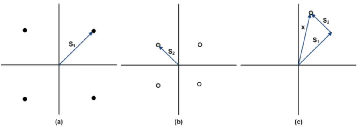
The fundamental concept of SC is that it is capable of encoding a message for a user associated with poor channel conditions at a lower rate and then superimpose the signal of a user having better channel conditions on it. Inspired by the solid foundations laid down from an information theory perspective, researchers became motivated to apply SC to diverse channels, such as interference channels, relay channels , MA channels [28]. Fig 2.5 shows an example of SC encoding.
Fig 2.5 : An example of SC encoding (a) signal constellation of user 1(b)signal constellation of
user 2 (c) constellation of superposed signal. [29].
Successive Interference Cancellation (SIC)
:It has been widely exploited that the network capacity can be substantially improved with the aid of efficient interference management, hence SIC is regarded as a promising IC technique in wireless networks. By invoking the following procedure, it enables the user having the strongest signal to be detected first, who has hence the least interference-contaminated signal. Then, the strongest user re-encodes and remodulates its signal, which is then subtracted from the composite signal.
The same procedure is followed by the second strongest signal, which has in fact
become the strongest signal. When all but one of the signals was detected, the weakest user decodes its information without suffering from any interference at all [28].
2.8 Advantages :
1) Higher spectral efficiency: By exploiting the power domain for user multiplexing, NOMA
systems are able to accommodate more users to cope with system overload.
2) Better utilization of heterogeneity of channel conditions: NOMA schemes intentionally
multiplex strong users with weak users to exploit the heterogeneity of channel condition.
3) Enhanced user fairness: By relaxing the orthogonal constraint of OMA, NOMA enables a
more flexible management of radio resources and offers an efficient way to enhance user fairness via appropriate resource allocation .
4) Applicability to diverse QoS requirements: NOMA is able to accommodate more users
with different types of QoS requests on the same subcarrier.
2.9 Disadvantages :
1) The BS needs to know the perfect channel state information (CSI) to arrange the SIC
decoding order, which increases the CSI feedback overhead.
2) The SIC process introduces a higher computational complexity and delay at the receiver
side, especially for multicarrier and multiuser systems.
3) The strong users have to know the power allocation of the weaker users in order to perform
SIC, which also increases the system signalling overhead.
4) Allocating more power to the weak users, who are generally in the cell-edge, will introduce
2.10 Applications :
Visible Light Communication
:Similar performance gains as seen in the RF case can be expected if NOMA is implemented in VLC. As the channel generally does not change most of the time, the decoding becomes simpler.
MIMO-NOMA
:The combination of MU-MIMO which allows multiple beams and NOMA within a single beam can lead to a greater capacity of the system.
Internet of Things
:The scenario in IoT is massive connectivity. Exploitation of Non-Orthogonal resources as a means to enhance connectivity is subject to research.
SoDeMA
:Software Defined Multiple Access is an active research area where the best multiple access scheme is chosen based on the conditions of the system. For example, if we only have a small number of users and they do not have a large variance in SNR, OMA would be preferable to NOMA. Similarly, different scenarios call for different multiple access schemes [27].
CR-NOMA
:Integrating NOMA techniques into CR networks (CRNs) has the tremendous potential to improve spectral efficiency and increase the system capacity. However, there are many technical challenges due to the severe interference caused by using NOMA [31].
2.12 Conclusion :
As we have seen in chapter 1, in the presence of 5G we cannot neglect the 4G and in existence of the Small Cells we don’t dispense with the traditional cells, also in existence of NOMA we don’t eliminate the presence of OMA, choosing between them is due to the number of users.
In this chapter we have learned about the most important terms for NOMA: SC, SIC. And the applications: MIMO-NOMA, SoDeMA, CR-NOMA. Also, the challenges faced.
Surely, beyond the walls of laboratories, researchers are working to find Solutions for all those challenges who knows maybe this year or after, this technology will be released to the world with all its features and solutions.
NOMA is divided into two categories: power-domain NOMA and code-domain NOMA. In the next chapter, we will be focusing on SCMA..
Chapter 3:
Sparse Code Multiple Access (SCMA)
Overview
3.1 Introduction
:Between several candidates for the 5G multiple access schemes, we found the most likely scheme could be SCMA. In this chapter, we will focus on the SCMA system model then we will be explaining the function of these blocks consisted of this chain. Also, we will see what it is PRE Mapping? and how to design a codebook?
3.2
System model :
Sparse code multiple access is a form of NOMA scheme which is based on a multi-dimensional codebook [26].
In SCMA, bit streams are directly mapped to different sparse codewords. All codewords in the same codebook contain zeros in the same two dimensions, and the positions of the zeros in the different codebooks are distinct so as to facilitate the collision avoidance of any two users [17].
An SCMA transmission system can be simply illuminated in Fig 3.1. It will be discussed in the following sections.
Fig 3.1 : SCMA uplink chain with channel coding [32].
3.2.1 Channel encoding :
Channel encoding allows transmission of the message generated by the source through the channel. The channel encoder accepts as input a set of messages of fixed length and maps the source alphabet into a channel alphabet, then adds a set of redundancy symbols, and finally sends the message through the channel [33].
There are three channel encoding schemes: turbo, LDPC and polar codes. These schemes were selected as candidates for 5th generation wireless communications (5G), due to their good performance, and low complexity state-of-the-art implementation [34], but in this chapter we are more concerned in turbo codes, for more information, go to page [34].
Turbo codes are a class of high-performance FEC codes developed around 1990–91 , which were the first practical codes to closely approach the channel capacity, a theoretical
maximum for the code rate at which reliable communication is still possible given a specific noise level. Turbo codes are used in 3G/4G mobile communications (e.g., in UMTS and LTE) and in (deep space) satellite communications as well as other applications where designers seek to achieve reliable information transfer over bandwidth- or latency-constrained communication links in the presence of data-corrupting noise. Turbo codes compete with LDPC codes, which provide similar performance. The name "turbo code" arose from the feedback loop used during normal turbo code decoding, which was analogized to the exhaust feedback used for engine turbocharging [35 ]. More details about this code can be found in [36],[37],[38].
3.2.2 SCMA encoding :
An SCMA encoding procedure is defined as a mapping from m bits to an K-dimensional complex codebook of size M, where M = 2m .
K-dimensional complex codewords consist of N < K non-zero elements. Each user j has a unique codebook from the set of J codebooks, i. e. J users (usually called layers) can transmit information over K orthogonal resources simultaneously.
The overloading factor is defined as λ = J/K. An example of codebook set for J = 6 and K = 4 is presented below : 𝐶𝐵1 = [ 0 −0.1815 − 0.1318𝑗 0 0.7851 0 −0.6351 − 0.4615𝑗 0 −0.2243 0 0.6351 + 0.4615𝑗 0 0.2243 0 0.1815 + 0.1318𝑗 0 −0.7851 ] 𝑇 , 𝐶𝐵2 = [ 0.7851 0 −0.1815 − 0.1318𝑗 0 −0.2243 0 −0.6351 − 0.4615𝑗 0 0.2243 0 0.6351 + 0.4615𝑗 0 −0.7851 0 0.1815 + 0.1318𝑗 0 ] 𝑇 , 𝐶𝐵3 = [ −0.6351 + 0.4615𝑗 0.1392 − 0.1759𝑗 0 0 0.1815 − 0.1318𝑗 0.4873 − 0.6156𝑗 0 0 −0.1815 + 0.1318𝑗 −0.4873 + 0.6156𝑗 0 0 0.6351 − 0.4615𝑗 −0.1392 + 0.1759𝑗 0 0 ] 𝑇 , 𝐶𝐵4 = [ 0 0 0.7851 −0.0055 − 0.2242𝑗 0 0 −0.2243 −0.0193 − 0.7848𝑗 0 0 0.2243 0.0193 + 0.7848𝑗 0 0 −0.7851 0.0055 + 0.2242𝑗 ] 𝑇 , 𝐶𝐵5 = [ −0.0055 − 0.2212𝑗 0 0 −0.6351 + 0.4615𝑗 −0.0193 − 0.7848𝑗 0 0 0.1815 − 0.1318𝑗 0.0193 + 0.7848𝑗 0 0 −0.1815 + 0.1318𝑗 0.0055 + 0.2242𝑗 0 0 0.6351 − 0.4615𝑗 ] 𝑇 ,
𝐶𝐵6 = [ 0 0.7851 0.1392 − 0.1759𝑗 0 0 −0.2243 0.4873 − 0.6156𝑗 0 0 0.2243 −0.4873 + 0.6156𝑗 0 0 −0.7851 −0.1392 + 0.1759𝑗 0 ] 𝑇 .
where CBj is a codebook for user j. The columns of codebooks are codewords, thus every user maps m = 2 bits to one of M = 4 four-dimensional codewords [39].
As the performance of SCMA strongly depends on the multi-dimensional codebooks, codebook design constitutes one of the most important issues for SCMA, and it is what distinguishes SCMA from other non-orthogonal multiple access schemes.
Incorporating a sophisticated codebook design into SCMA has the potential of significantly improving the spectrum efficiency, and reducing the detection complexity [40].
When we have looked so closely, we have found that PRE Mapping in the original SCMA system model the same as shown in figure 3.2.
Fig 3.2 : Original SCMA system model with channel coding [41].
3.2.3 PRE Mapping :
The main idea is that we have ‘Codebook design in SCMA encoding’ but it is not totally correct. Because, the codebook design is distributed to blocks of PRE-Mapping as illustrated in Fig 3.3.
3.2.3.1 Scrambling :
Scrambling is a technique that does not increase the number of bits and does provide synchronization. Problem with technique like Bipolar AMI is that continuous sequence of zero’s create synchronization problems one solution to this is Scrambling. There are two common scrambling techniques:
B8ZS .
HDB3[43].More details about the B8ZS and HDB3 codes can be found in the same reference [43].
3.2.3.2 Modulation Techniques :
The UMB physical layer uses the following constellations for modulation. The type of modulation used depends on the channel and the parameters negotiated by higher layer protocols:
1-QPSK Modulation :
In case of 1-QPSK, a group of 2 bits is mapped into a complex modulation symbol (mI(k) and mQ(k)) as given by the following tab (3.1), and fig(3.4) :
Modulator Input Bits Modulation Symbols
S1 S0 mI(k) mQ(k) 0 0 D D 0 1 -D D 1 0 D -D 1 1 -D -D Note: 𝐷 = 1/√2
Tab 3.1 : The values for the constellations for QPSK Fig 3.4 : Signal constellation for QPSK
16-QAM modulation :
In case of 16 QAM modulation, a group pf 4 bits [s3,s2,s1,s0] are mapped into the signal
constellation as given in fig (3.5):
Fig 3.5 : Signal constellation for 16-QAM Modulation
Here, A = 1/√10.
The I and Q parts of the modulation symbol are given by the real and imaginary parts of the symbol mapping in the complex space. For ex: for [s3 s2 s1 s0] = 1000, from the figure above,
mI(k) = 3A and mQ(k) = -3A.
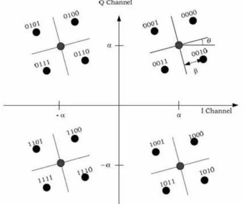
Hierarchical or Layered Modulation :
In general, layered modulation can be a superposition of any two modulation schemes. For Broadcast and Multicast Services, a QPSK enhancement layer may be superposed on a base QPSK or 16-QAM layer to obtain the resultant signal constellation. The energy ratio r is the power ratio between the base layer and the enhancement layer. The enhancement layer is rotated by the angle in the counter-clockwise direction [44]. In the next section, we will be explained this point at the special case to create codebook.
Modulation with QPSK Base Layer and QPSK Enhancement Layer :
Each modulation symbol contains 4 bits, [s3, s2, s1, s0], where s2 and s0 shall be from the base
layer and s3 and s1 shall be from the enhancement layer. For the energy ratio r between the base
layer and enhancement layer, α=√(r/2(1+r)) and β=√(1/2(1+r)) define the constellation completely. Fig 3.6 shows the signal constellation of the layered modulator. The complex modulation symbol S = (mI, mQ) for each [s3, s2, s1, s0] is just the real and imaginary parts
respectively of the corresponding constellation symbol. For ex: for [s3 s2 s1 s0] = 0000,
mI= α + β √cos(θ + П/4) and mQ= α + β √sin(θ + П/4).
Fig 3.6 : Signal Constellation for Layered Modulation with QPSK Base Layer and a QPSK
Modulation with 16-QAM Base Layer and QPSK Enhancement Layer :
Each modulation symbol contains 6 bits, [s5,s4,s3, s2, s1, s0], where s4,s3,s1 and s0 shall be
from the base layer and s5 and s2 shall be from the enhancement layer. For the energy ratio r
between the base layer and enhancement layer, α=√(r/10(1+r)) and β=√(1/2(1+r)) define the constellation completely. Figure 3.7 shows the signal constellation of the layered modulator. The complex modulation symbol S = (mI, mQ) for each [s3, s2, s1, s0] is just the real and
imaginary parts respectively of the corresponding constellation symbol. For ex:
for [s5 s4 s3 s2 s1 s0] = 000000, mI= 3α + β √cos(θ + П/4) and mQ= 3α + β √sin(θ + П/4) [44].
Fig 3.7 : Signal constellation for Layered Modulation with a 16-QAM Base Layer and a QPSK
Constellation Operation :
The main operation is to create a codebook related to constellation firstly, then we will see this operation :
1) Proposed complex N-dimension constellation :
The proposed basic complex N-dimension constellation concentrates on increasing the minimum Euclidean distance. As Turbo code is applied as the channel coding , Turbo TCM technology is used to design the basic complex N-dimension constellation. TCM, which combines coding with modulation, can obtain a coding gain in bandwidth and power limited system, but the coding gain of TCM is limited. Benefiting from multi-dimension constellation, multi-dimension TCM increases not only the minimum Euclidean distance but also the coding gain . A proposed basic complex N-dimension signal can be constructed by N Cartesian products of two-dimension signals.
In other words, the transmitter sends a complex N-dimension signal, which is equivalent to sending N two-dimension signals, i.e. SN =S ×S ×….×S (N times).
Turbo TCM can be seen as two parallel concatenated Unger-boeck Trellis codes with code rate k/(k + 1). Fig 3.8 shows the structure of Turbo TCM .More details about the structure of Turbo TCM can be found in [45].
2) Phase Rotation :
As a basic rule, the minimum Euclidean distance is the determinant of the performance of constellation in AWGN channel, while the performance of constellation in fading channel
is related to the diversity and product distance between any constellation points. It can be achieved via phase rotation.
The phase optimal algorithm can be expressed in two steps as follows:
Step 1 : For a given constellation, choose a desired level of partitioning. For example, 16QAM
can be partitioned such that there are eight, four, two, or one points in each sub-constellation.
Step 2 : Find the optimal rotation parameter θ∗ such that (1) : 𝜃∗ = arg 𝑚𝑎𝑥
𝜃min (𝑀𝐶𝑃𝐷𝜃(1), … , 𝑀𝐶𝑃𝐷𝜃(𝑚𝑠) , … , 𝑀𝐶𝑃𝐷𝜃(𝑀𝑠)),
1 ≤ 𝑚𝑠 ≤ 𝑀𝑠 , (1)
𝐶𝑃𝐷 = ∏ (𝑐𝐿𝑐 𝑘𝑖 − 𝑐𝑘𝑗 ), (2)
where Ms is the number of distinct sub-constellations, 𝑀𝐶𝑃𝐷𝜃(𝑚𝑠) is the minimum coordinate
product distance (CPD (2)) for the ms-th sub-constellation rotated by θ, Lc isthe number of
distinct coordinates between any constellation points, and 𝑐𝑘𝑖 is the k-th dimension of constellation point i.
In K-dimension constellation, a general rotation may be represented by the product of k(k−1)
2
Givens rotation matrices, each parameterized by a single parameter θk1,k2 as shown in the
formula (3) : J(k1, k2, θk1,k2) = [ 1… cos(θ⋮ ⋮ k1,k2) … −sin(θk1,k2) … ⋮ ⋮ … sin(θk1,k2) … cos(θk1,k2) … ⋮ ⋮ 1 ] (3)
Accordingly, the optimization must be carried out over the k(k−1)
2 -dimension vector
![Fig 1.1: D2D and Cellular communications share the same radio resources [6].](https://thumb-eu.123doks.com/thumbv2/123doknet/12274719.321961/19.892.210.746.738.929/fig-d-d-cellular-communications-share-radio-resources.webp)

![Fig 2.2 : OFDMA and SC-FDMA [20].](https://thumb-eu.123doks.com/thumbv2/123doknet/12274719.321961/30.892.141.815.676.999/fig-ofdma-sc-fdma.webp)
![Fig 2.3 : Possible NOMA Solution [22].](https://thumb-eu.123doks.com/thumbv2/123doknet/12274719.321961/31.892.296.633.432.706/fig-possible-noma-solution.webp)
![Fig 2.4 : Downlink NOMA in a single cell with one BS and two users [24].](https://thumb-eu.123doks.com/thumbv2/123doknet/12274719.321961/32.892.165.724.437.822/fig-downlink-noma-single-cell-bs-users.webp)
![Fig 3.1 : SCMA uplink chain with channel coding [32].](https://thumb-eu.123doks.com/thumbv2/123doknet/12274719.321961/40.892.181.831.555.741/fig-scma-uplink-chain-with-channel-coding.webp)
![Fig 3.2 : Original SCMA system model with channel coding [41].](https://thumb-eu.123doks.com/thumbv2/123doknet/12274719.321961/42.892.174.784.473.704/fig-original-scma-model-channel-coding.webp)