HAL Id: hal-01667779
https://hal-mines-paristech.archives-ouvertes.fr/hal-01667779
Submitted on 19 Dec 2017
HAL is a multi-disciplinary open access
archive for the deposit and dissemination of
sci-entific research documents, whether they are
pub-lished or not. The documents may come from
teaching and research institutions in France or
abroad, or from public or private research centers.
L’archive ouverte pluridisciplinaire HAL, est
destinée au dépôt et à la diffusion de documents
scientifiques de niveau recherche, publiés ou non,
émanant des établissements d’enseignement et de
recherche français ou étrangers, des laboratoires
publics ou privés.
An Advanced 3D Mathematical Model for a 6-high
Tandem Cold Rolling Process
Xiawei Feng, Pierre Montmitonnet, Quan Yang, Anrui He, Xiaochen Wang
To cite this version:
Xiawei Feng, Pierre Montmitonnet, Quan Yang, Anrui He, Xiaochen Wang. An Advanced 3D
Math-ematical Model for a 6-high Tandem Cold Rolling Process. Procedia Engineering, Elsevier, 2017,
Part of special issue: International Conference on the Technology of Plasticity, ICTP 2017, 17-22
September 2017, Cambridge, United Kingdom, 207, pp.1379 - 1384. �10.1016/j.proeng.2017.10.900�.
�hal-01667779�
ScienceDirect
Available online at www.sciencedirect.com
Procedia Engineering 207 (2017) 1379–1384
1877-7058 © 2017 The Authors. Published by Elsevier Ltd.
Peer-review under responsibility of the scientific committee of the International Conference on the Technology of Plasticity. 10.1016/j.proeng.2017.10.900
10.1016/j.proeng.2017.10.900
© 2017 The Authors. Published by Elsevier Ltd.
Peer-review under responsibility of the scientific committee of the International Conference on the Technology of Plasticity.
1877-7058
ScienceDirect
Procedia Engineering 00 (2017) 000–000
www.elsevier.com/locate/procedia
1877-7058 © 2017 The Authors. Published by Elsevier Ltd.
Peer-review under responsibility of
the scientific committee of the International Conference on the Technology of
Plasticity
.International Conference on the Technology of Plasticity, ICTP 2017, 17-22 September 2017,
Cambridge, United Kingdom
An Advanced 3D Mathematical Model
for a 6-high Tandem Cold Rolling Process
Xiawei Feng
a*, Pierre Montmitonnet
b,
Quan Yang
a, Anrui He
a, Xiaochen Wang
aaUniversity of Science and Technology Beijing – NERCAR, No. 30, Xueyuan Road, Haidian District, Beijing,100083, China bMINES ParisTech – CEMEF,CS 10207 Rue Claude Daunesse, Sophia Antipolis, 06904, France
Abstract
The present paper focuses on the validation of on-going efforts made to develop more advanced 3D mathematical model for cold rolling strip process [8]. Following [2], the model uses the multi-slab strategy to deal with the differential reduction in the transverse direction due to roll deformation, and analytical solutions of roll bending and flattening discretized by the Influence Function Method (IFM). Furthermore, the model has been extended to incorporate elastic deformation of strip and to be fit for 6-high rolling mills with shiftable work roll (WR) or Intermediate Rolls (IR) as well as 4-6-high mills. Validation is performed by using FEM solutions (Abaqus® implicit) as references: a 2D quasi-static model to check the slab method under rigid work roll condition; a 3D FEM to discuss the assumption of small lateral flow of strip; a comparison of FEM and IFM with regard to 6-high roller stack deformation with intermediate roll shifting. All these steps are essential to gain more insight into the mechanism of cold rolling strip and to guide future development work of the mathematical model.
© 2017 The Authors. Published by Elsevier Ltd.
Peer-review under responsibility of
the scientific committee of the International Conference on the Technology
of Plasticity
.Keywords: Cold rolling strip; Slab method; Influence Function Method; Finite Element Method
* Corresponding author. Tel.: +86 (0)10-62332947; fax: +86 (0)10-62332947.
E-mail address: b20130518@xs.ustb.edu.cn
Available online at www.sciencedirect.com
ScienceDirect
Procedia Engineering 00 (2017) 000–000
www.elsevier.com/locate/procedia
1877-7058 © 2017 The Authors. Published by Elsevier Ltd.
Peer-review under responsibility of
the scientific committee of the International Conference on the Technology of
Plasticity
.International Conference on the Technology of Plasticity, ICTP 2017, 17-22 September 2017,
Cambridge, United Kingdom
An Advanced 3D Mathematical Model
for a 6-high Tandem Cold Rolling Process
Xiawei Feng
a*, Pierre Montmitonnet
b,
Quan Yang
a, Anrui He
a, Xiaochen Wang
aaUniversity of Science and Technology Beijing – NERCAR, No. 30, Xueyuan Road, Haidian District, Beijing,100083, China bMINES ParisTech – CEMEF,CS 10207 Rue Claude Daunesse, Sophia Antipolis, 06904, France
Abstract
The present paper focuses on the validation of on-going efforts made to develop more advanced 3D mathematical model for cold rolling strip process [8]. Following [2], the model uses the multi-slab strategy to deal with the differential reduction in the transverse direction due to roll deformation, and analytical solutions of roll bending and flattening discretized by the Influence Function Method (IFM). Furthermore, the model has been extended to incorporate elastic deformation of strip and to be fit for 6-high rolling mills with shiftable work roll (WR) or Intermediate Rolls (IR) as well as 4-6-high mills. Validation is performed by using FEM solutions (Abaqus® implicit) as references: a 2D quasi-static model to check the slab method under rigid work roll condition; a 3D FEM to discuss the assumption of small lateral flow of strip; a comparison of FEM and IFM with regard to 6-high roller stack deformation with intermediate roll shifting. All these steps are essential to gain more insight into the mechanism of cold rolling strip and to guide future development work of the mathematical model.
© 2017 The Authors. Published by Elsevier Ltd.
Peer-review under responsibility of
the scientific committee of the International Conference on the Technology
of Plasticity
.Keywords: Cold rolling strip; Slab method; Influence Function Method; Finite Element Method
* Corresponding author. Tel.: +86 (0)10-62332947; fax: +86 (0)10-62332947.
1380 Xiawei Feng et al. / Procedia Engineering 207 (2017) 1379–1384
2 Xiawei Feng et al. / Procedia Engineering 00 (2017) 000–000
1. Introduction
Modern steel strip cold rolling involves tandem mills consisting of typically five successive six-high (6 rolls) stands with complex actuations : at each stand, work roll (WR) and intermediate roll (IR) shifting, roll bending forces (FRB) allow fast adaptation whereas roll grinding crown brings a constant, first order correction to roll bending and flattening. These are necessary, powerful tools for an optimal strip profile and flatness, but modelling is needed to design their multivariable control system.
For this particularly important metal forming process, a number of models have been developed for a long time, see e.g. [1-3] and a review in [4]. However on modern mills, WR and IR roll shifting make it a fully 3D problem in which planar symmetries are replaced by skew symmetry, requiring extension into more general models. Moreover, rolling harder steel grades results in higher stresses, calling for more robust deformation models. Finally, due to the large number of parameters to be included in the design procedure, these mathematical models must bring about a high quality/cost ratio to allow intensive parametric studies.
Many methods are currently used to model strip deformation: Slab Method (SM) in 2D, Upper Bound Method (UBM) or Finite Element Method (FEM) for both 2D and 3D; an asymptotic approach has also been applied to the calculation of 2D strip deformation [5], offering interesting mathematical insight but with limited practical capacities. To model roll bending, researchers use either the beam theory or the FEM, whereas flattening is calculated by e.g. Boussinesq’s analytical equations or the FEM. Most recently, a boundary element method using the Mindlin’s solution has been proposed to solve the elastic flattening deformation of the whole roll stack [6]; however to cope with complex boundary conditions, these authors had to introduce FEM-based approximate corrections, just as in the semi-analytical model of Hacquin [3] which therefore remains as precise and faster.
To deal with the whole (strip + rolls + actuators) problem, any combination of these bricks can be, and has been, proposed, the coupling technique being an essential ingredient [4]. This has been done using e.g. the FEM [7] for the whole systems but the cost is very high. The present paper is inspired from Pawelski’s work [2], whereby a semi-analytical model of the roll deformation is discretized by the Influence Function Method (IFM) whereas a series of longitudinal 2D slabs modelled with the SM deal with the differential reduction across the width induced by roll bending and flattening. Such approaches to predict rolled strip crown have been experimentally validated in the past under various rolling conditions for mild steel relatively thick strips. In a previous paper [8], the present authors have improved the accuracy of the model of [2] by relaxing Hitchcock’s assumption of circular work roll surface and adding discretization technique of Influence Function Method in rolling direction, in an effort to address harder and thinner strips in the future. The present paper is devoted to the validation of two bricks of the model. First, the elastic-plastic SM is compared with 2D plane strain FEM. Secondly, 3D FEM is used to check (1) the assumption of viewing strip as a series of slabs at different transverse positions and (2) the roll stack elastic deformation model based on the Influence Function Method (IFM).
Nomenclature
x, y, z Cartesian coordinates in the rolling, transverse and thickness direction, respectively ε strain, upper script p for plastic strain
2. Brief models description
2.1. Strip deformation
The present Slab Model is based on the variant proposed by Le and Sutcliffe [9] (where full details can be found) of the SM initiated by von Karman in 1925. The main assumptions are plane strain and stress uniformity in the normal direction (z), resulting in a 1D ordinary differential equation (ODE) in the normal and tangential stress. The friction stress is expressed by a Coulomb law; the stick / slip kinematical transition is smoothed by a regularization technique [10] using the tangential relative velocity. An elastic-plastic model is used, based on Prandtl-Reuss additive decomposition of the strain rate and including work-hardening. Taking the back tension as initial condition,
the ODE is integrated; due to the change of the sign of friction at the unknown location of the neutral point, an iterative procedure is needed to ensure that the exit stress matches the front tension: a bisection method is used for the initial two iterations, a secant method further on.
It must be noted that special care must be taken when rolling hard and thin material, because of the large elastic deformation of WR which may result in a central elastic zone (or “contained plastic”, or “no-slip”) inserted between the entry and exit plastic zones (with further elastic zones at entry and exit of course). The integration with changing sets of equations proves difficult in the central area due to spurious sign change of the local roll profile slope under extreme contact pressures. Therefore, [9] inverts the scheme in the central area and deduce normal and tangential stresses not from equilibrium equation integration, but from the no-slip condition, both strip and roll being elastic. This option is however not used in the present paper which is thus limited to rolling of thicker strips.
2.2. IFM model of roll stack deformation
For 4/6 high roll stacks, the authors follow the 3D semi-analytical elastic roll deformation model fully described by Hacquin et al. [3,4]. It combines roll bending based on Timoshenko’s beam theory, roll flattening based on Boussinesq’s equations for a semi-infinite solid arbitrarily loaded on its surface, Hertz contact theory for the roll - roll contact. End effect for the complex geometry and boundary conditions of the roll barrel edge have been corrected by analytical expressions derived from extensive FEM comparisons. All equations are discretized by a 3D influence function method. Due to the unknown roll – roll contact areas, the resulting equations are non-linear and are solve by Newton-Raphson scheme.
3. Result and discussion
3.1. Plane strain study: validation of Slab Method against FEM
Table 1. Parameters used for the rolling pass Variables Value Inlet/exit thickness 1.6/1.152mm Roller radius 100mm Back/front tension stress 65/75MPa Young’s Modulus (strip) 210GPa Poisson’s ratio (strip) 0.3 Tresca yield stress 230+1200* ε
Coulomb friction coefficient 0.08(bite-in),0.075(quasi-static) Strip width 200mm
Roller crown 5µm
First, the comparison between SM and FEM (Abaqus® implicit, quasi-static 2D) is presented for the elastic-plastic strip deformation. Top/bottom symmetry has been assumed, rolls are rigid. With about 50x5 CPS4R elements and a time step of 2e-4 second in the roll bite, FE convergence has been reached. To deal with the engagement of the strip in the roll bite, a three-step strategy has been used with the FEM: first, setting a firm contact, then bite-in with a higher friction coefficient whereas roll accelerates, finally reaching a quasi-steady rolling process with parameters of table 1.
The SM calculation costs only a few seconds whereas tens of minutes are needed for FEM to reach a quasi-steady state. Fig .1 (a) shows that there is a shear effect at bite entry, as seen by the non-strictly vertical contour lines of the strain; it could be evidenced by plotting the strain rate map with an adapted (logarithmic) scale, but this is not done here due to the small impact of this feature. This point is indeed marked by a slight normal pressure peak in the
1382 Xiawei Feng et al. / Procedia Engineering 207 (2017) 1379–1384
4 Xiawei Feng et al. / Procedia Engineering 00 (2017) 000–000
FEM results, but again it does not impair the good agreement of the global profiles (Fig .1 (b)). Furthermore, this effect would further reduce if thinner strips (higher bite length / thickness ratio [4]) were simulated such as in last passes of cold tandem mill, in double reduction or even in foil rolling, where the major problems arise.
Fig. 1. 2D strip deformation models comparison, SM vs FEM. (a) equivalent plastic strain; (b) normal pressure
3.2. 3D Case: discussion of the plane strain assumption
From the above 2D case, a 3D case was built with the same, uniform back/front tensions assumed across the transverse (y) direction. Constitutive models are isotropic, i.e. friction in the y direction is the same as in x direction. A rigid work roll with a 5 µm quadratic crown is used to bring a concave shape change
Fig. 2. Top view of the rolled strip during 3D FEM modelling. (a) y-displacement in the strip; (b) stress map xx(x,y)
Fig. 2 (a) confirms that under the abovementioned assumptions, the lateral flow is present but small – spread is about 0.08mm in the steady state, to be compared with half strip width 100mm. This fundamental assumption of the multi-slab model is therefore validated. On the other hand, Fig.2 (b) shows that xx(y) varies significantly; on either
sides of the roll bite (but with more intensity at exit), a strong tension is induced in the edges which are less deformed due to the roll crown – and therefore tend to have a lower forward velocity. Note that steady state has not been reached exactly, which would require rolling a length of approximately twice the strip width, i.e. 400 mm.
(Avg: 75%)
PE, Max. In−Plane Principal
0.000 0.025 0.051 0.076 0.102 0.127 0.152 0.178 0.203 Rolling direction 0 200 400 600 800 -8 -6 -4 -2 0 2 N or m al p re ss ur e (M Pa ) x (mm) FEM Slab Method
−0.044 −0.020 0.003 0.027 0.051 0.075 0.099 0.123 0.147 0.171 R ol lin g di re ct io n Edge Edge Contact start Contact end −267.505 −204.174 −140.844 −77.513 −14.183 49.148 112.478 175.809 239.139 302.470 R ol lin g di re ct io n Edge Edge Contact start Contact end a b a b
3.3. 4/6 high roll stack modelling: 3D FEM vs IFM.
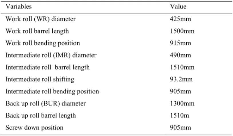
The FE model has been set up to study the elastic deformation of a 6-high roll stack with IR shifting. Parameters are given in Table 2. Bending forces of 46kN and 200kN have been applied on work rolls and intermediate rolls respectively to counter-bend WR under an assumed uniform rolling load of 8kN/mm (the strip deformation is not modelled in this section). The mesh is refined at the roll/roll contact areas, see Fig.3 (a) and (b). Nodal contact forces from FEM have been reprocessed into a contact line load, in order to be compared with IFM.
Table 2. Parameters used for the elastic deformation of the rollers
Variables Value
Work roll (WR) diameter 425mm Work roll barrel length 1500mm Work roll bending position 915mm Intermediate roll (IMR) diameter 490mm Intermediate roll barrel length 1510mm Intermediate roll shifting 93.2mm Intermediate roll bending position 905mm Back up roll (BUR) diameter 1300mm Back up roll barrel length
Screw down position
1510m 905mm
Fig. 3 (c) shows that the IFM roll stack elastic deformation model has a great precision at a low cost. It took 6 to 12 Newton-Raphson’s iterations to achieve convergence (remember that the roll stack model is non-linear due to evolving roll/roll contact); the total cost is a few seconds, while the load difference with FEM is negligible.
4. Conclusion
Current progress of developing mathematical model with better cost/quality ratio for cold rolling strip process has been reported in the present paper. It revisits the model of Pawelski [6], which took advantage of the engineering feature of cold rolling that the reduction in thickness only results in elongation in rolling direction (lateral spread is very small). Progress has been made by incorporating an elastic-plastic Slab Method and an Influence Function Method for 4/6-high roll stack compilation with Hacquin’s correction.
The advantage and limitations of the developed model have been discussed. It is shown that the present model matches FEM results at a lower computational cost, in terms of strip deformation (SM predicting local roll load) and the transmission of contact loads through the roll stack. A good precision can therefore be expected on the prediction of strip crown (transverse thickness profile). What is neglected is the intrinsically 3D problem of strip lateral widening/shrinking, which is important in itself (for width tolerance control) and may also impact very locally the load distribution near the edge and the edge-drop defect; flatness of course cannot be directly addressed, it needs to be processed by a different model from a comparison of entry and exit strip crowns.
It should be pointed out that there are few experimental results on the contact mechanics of cold strip rolling in the transverse direction; also the question of friction anisotropy and its potential consequences remains open. Further efforts by the authors to achieve a fully coupled iterative model will be reported in future papers.
1384 Xiawei Feng et al. / Procedia Engineering 207 (2017) 1379–1384
6 Xiawei Feng et al. / Procedia Engineering 00 (2017) 000–000
Fig.3. Checking roll stack model. (a) the FEM mesh; (b) focus on the edges of contacts where mesh is refined; (c) FEM / IFM comparison of roll – roll contact loads
Acknowledgements
The authors acknowledge the financial support of China Scholarship Council, the funding of Anshan Iron & Steel Corporation.
References
[1] K.N. Shohet, N.A. Townsend, Roll bending methods of crown control in four-high plate mills, J. Iron Steel Inst. 206, 11 (1968) 1088-1098. [2] O. Pawelski, H. Teutsch. A mathematical model for computing the distribution of loads and thickness in the width direction of a strip
rolled in a 4-hi cold rolling mill, Eng. Fract. Mech. 21, 4 (1985) 853-859.
[3] A. Hacquin, P. Montmitonnet and J.P. Guillerault, A three-dimensional semi-analytical model of rolling stand deformation with finite element validation, Eur. J. Mech.-A/Solids 17, 1 (1998) 79-106.
[4] P. Montmitonnet, Hot and cold strip rolling processes, Comp. Meth. Appl. Mechs Engng 195 (2006) 6604-6625
[5] J. J. Minton, C. J. Cawthorn, and E. J. Brambley. "Asymptotic analysis of asymmetric thin sheet rolling." International Journal of
Mechanical Sciences (2016), p.36-48.
[6] Z. Yuan, H. Xiao and H. Xie, Practice of Improving Roll Deformation Theory in Strip Rolling Process Based on Boundary Integral Equation Method. Metallurgical and Materials Transactions A (2014), p. 1019-1026.
[7] T.H. Kim, W.H. Lee, S.M. Hwang, An integrated FE process model for the prediction of strip profile in flat rolling, ISIJ Int. 43, 12 (2003) 1947-1956
[8] X. Feng, Q. Yang, P. Montmitonnet, X. Wang. An advanced strip/ roll stack coupled method for tandem cold rolling process of a six-high mill, in Proc. 10th International Rolling Conference, Graz, Austria, published by ASMET, Vienna, 2016, p. 495-499.
[9] H. R. Le, M.P.F. Sutcliffe, A robust model for rolling of thin strip and foil, Int. J. Mech. Sci. 43 (2001) 1405-1419.
[10] P. Gratacos, P. Montmitonnet, C. Fromholz, J.-L. Chenot, A plane strain elastoplastic finite element model for cold rolling of thin strip, Int. J. Mech. Sci. 34, 3 (1992), pp.195-210. ZY X X Y Z 0 5000 10000 15000 20000 25000 0 200 400 600 800 1000 1200 1400 1600 1800 co nt ac t l oa d (N /m m ) Position (mm) IMR-BUR TEC3 IMR-BUR Abaqus WR-IMR TEC3 WR-IMR Abaqus a b c