O
pen
A
rchive
T
OULOUSE
A
rchive
O
uverte (
OATAO
)
OATAO is an open access repository that collects the work of Toulouse researchers and
makes it freely available over the web where possible.
This is an author-deposited version published in :
http://oatao.univ-toulouse.fr/
Eprints ID : 18129
To link to this article :
DOI: 10.1049/cp.2016.0248
URL :
http://dx.doi.org/10.1049/cp.2016.0248
To cite this version :
Bernot, Alix and Trémouille, Gautier Optimisation and
adaptation of an existing aeronautic motor to an HVDC network. (2016) In:
8th IET International conference on Power Electronics, Machines and
Drives (PEMD 2016), 16 April 2016 - 21 April 2016 (Glasgow, United
Kingdom).
Any correspondence concerning this service should be sent to the repository
administrator:
[email protected]
Optimisation and adaptation of an existing aeronautic motor to an
HVDC network
A Bernot*
†, G Trémouille*
*IRT Saint-Exupéry, Toulouse, France, [email protected] †Permanent address: Zodiac Aerospace, France
Keywords: BLDC motor, non-overlapping winding, single
layer concentrated winding, aeronautic motor, HVDC network
Abstract
This paper presents the evolution of an airliner fan BLDC motor to adapt it to an HVDC electrical network. The guiding principle of the design is to increase reliability. A non-overlapping teeth winding is introduced to separate the motor phases in order to limit winding failures and especially partial discharges. The machine is also optimised using spoke-type magnets flux concentration rotor, in order to reduce total mass. The new machine is compared to the existing one with a finite elements method analysis.
1 Introduction
The evolution towards the more electric aircraft is expected to increase the airliner’s systems power density, reliability and efficiency, and to reduce maintenance [1]. Hydraulic and pneumatic systems, such as flight actuation (until recently hydraulic systems), cabin pressurization and de-icing (until recently warm air bleed systems), are eventually to be replaced by electrical systems. For instance, unlike a Skydrol pipe, an electrical wire does not leak, and there is no need of regularly changing the fluid, limiting the maintenance operations. On the A380, the introduction of 24 electrically-powered flight actuators alongside 16 hydraulic actuators has enabled a 500kg total mass gain on the aircraft, even if a single electrical actuator is heavier than a hydraulic one. However, the total on-board power increases steadily (more than 1MVA in the Boeing 787, first bleedless airliner, compared with 300kVA on board the Airbus A340). In order to achieve mass gains at the system level, the aircraft electrical network is evolving. Since the A380, the electrical generators are directly coupled to the reactor, without a mechanical gearbox, leading to a 360 to 800Hz variable frequency. This has led to the replacement of network-supplied AC induction machines by electronic-network-supplied permanent magnets BLDC machines. The electrical network voltage has doubled in the A350, from 115V to 230V, in order to reduce the copper wire masses. The manufacturers are now planning to replace the 230V three-phase electrical network by a 540V HVDC network, in order to remove the rectifier stages of the equipments, which now mainly use power electronics inverters with DC buses.
The studied motor is an existing airliner fan motor, powered by an inverter with a 270V DC bus, rectified from a 400Hz 115Vac three-phase network. It is a surface permanent magnet BLDC six-pole motor, with a six-step control power electronics. The advantage of BLDC six-step control is that there is no need for RTCA DO-178 software code to be certified, which is a costly process in the aircraft industry. The motor rated operating point is 7Nm at 15krpm. The operating point is permanent, with little speed variation, and the motor must operate at thermal equilibrium. The fan motor is naturally cooled by the forced airflow generated by the fan. This study is the adaptation of this motor to a DC bus voltage of 540V, which can either come from an HVDC network, or be rectified from a 400Hz 230V three-phase network. The driving design guidelines for the new motor are the improvement of reliability and mass, which are two major issues for aircraft motors. The new motor will be compared to the existing one.
2 Main failure modes
The aftersales main fault sources causing motor returns are, sorted by frequency:
- IGBT fault in the inverter - Bearing fault
- Winding fault, short-circuit - Winding fault, open-circuit
The first fault source, the IGBT fault, is typically due to high currents in the switch. It can occur with voltage-driven BLDC motor such as this one, with significant current ripples. In order to minimise this issue, the motor control strategy is to minimise the current ripple, instead of maximising the torque/current ratio.
The second fault source is the bearing fault. This can be due to unbalanced radial forces on the shaft. In order to minimise this issue, the motor will have to be somehow symmetric, in order to compensate the radial forces.
The third fault source is a winding short-circuit fault, either turn-to-turn, phase-to-phase or phase-to-mass. It can be due to mechanically damaged wire insulation during assembly, or simply to discharges caused by the high voltages. The rise of the DC bus voltage due to the aircraft electrical network evolution increases steadily the second problem, with the
appearance of partial discharges in the copper insulation. This issue is developed in detail in the next paragraph.
The fourth fault source is an open-circuit fault, which can be for instance a soldered joint breakup. This leads us to minimise the number of joints in the winding.
3 Partial discharges
The voltage rise generates higher constraints on the winding insulation. One problem is the appearance of small discharges inside small gas bubbles in the copper insulations, called partial discharges. These partial discharges cannot appear at the voltages generated by a 270Vdc inverter, since the voltages remain below Paschen’s law thresholds [2,3]. However, with voltages generated by a 540Vdc inverter, these partial discharges may appear. This effect is worsened by the pressure drop at higher altitudes: the pressure can decrease down to 200hPa at 12,000m (40,000 feet). It is also worsened by the voltage rise and fall speeds, which increase with the progressive introduction of wide-bandgap semiconductors, such as silicon carbide and gallium nitride. With commutation times as low as 10ns and dV/dt up to 50kV/!s, these new materials allow power electronics inverter with better efficiencies, but introduce here new challenges in the motor design.
The partial discharges slowly damage the insulation, reducing the motor life expectancy [2,3]. The lifespan of an airliner is 40 years, with 4,000 flight hours per year (11 hours per day), demanding electric machines lifetimes of 160,000 hours. The new motor design will then have to reduce the partial discharges in order to increase the motor’s lifespan.
The partial discharges appear mainly between two different phases, because there is the higher electrical constraint (with sometimes double the transistor’s dV/dt and the maximum voltage of the inverter between the two phases in certain commutation configurations). They can even also appear between two turns of the same wire when the voltage time travel of the voltage wave through the copper wire is too slow compared with the inverter commutation time. The insulation between two turns of the same coil is generally limited, with only the copper wire enamel and a very thin layer of resin, favouring these discharges risks.
On the other hand, the copper to iron insulation is generally good with the usual techniques, combining insulating paper, wire enamel and resin, with little partial discharges risks. Hence the main regions of the electric motor where these partial discharges are [2,3], by decreasing order of probability:
- Inside the end windings, between two phases - Inside a slot, between two phases
- Between two conductors of the same coil
In case of distributed windings, there is, most of the time, an overlap between the phases in the end windings. This is
particularly at risk and is the most likely place of partial discharges.
The second place of partial discharges is when two phases share the same slot. Even with insulating paper separating them, the high voltage difference and dV/dt may lead to partial discharges between the phases.
The third place is between the first and the last turn of the same coil. The voltage rise time of 50kV/!s achieved with SiC transistors can lead to an uneven rise of the electrical field near the copper wire, with up to 80% of the voltage located in the first turn at some point [2,3]. This may lead to partial discharges between the first and the last turn of the same coil if they are located next to each other.
4 Single layer concentrated winding
In order to minimise winding electrical stress and remove the partial discharges preferred places, we choose a single layer concentrated winding. It is a non-overlapping winding with one tooth out of two wound, according to figure 1.
Figure 1: single layer concentrated winding [4] This winding naturally limits partial discharges. The end windings never overlap between different phases, removing the first preferred place of partial discharges. There is only one phase in each slot, removing the second preferred place of partial discharges. Moreover, the winding is progressive, with the same number of turns of a phase on every sixth tooth, naturally keeping the first turn away from the last and limiting the third preferred place of partial discharges. Furthermore, there are some other advantages with this type of winding [4, 5, 6]. The end windings are shorter, leading to a lower resistance. A higher slot fill factor (>0.4) is easier to achieve, also lowering the resistance and the copper losses, improving the efficiency. The back-EMF is more easily rendered trapezoidal, which is more favourable for six-step control, leading to lower current and torque ripples. It is also easier to manufacture, with a smaller number of winding strings to insert, and a much easier inserting process. Since the copper wire is wound around the teeth, it is easier to insert a wire turn around a single tooth with a bigger slot than in a smaller slot separated by several small teeth; there is also no need of carefully counting the right number of small slots separating each wire strand.
There are however some drawbacks to this technique. The magnetomotive force has a higher harmonics content, which increase the iron losses, the mechanical vibrations and the acoustic noise.
5 Chosen architecture: 12/8 spoke-type interior
permanent magnet
5.1 Number of slots
The motor has three phases, so the number of stator slots has to be a multiple of 6 (each phase needs at least two slots, on every side of a slot). This number has to be kept low in order to minimise the pole number, for a smaller frequency (less iron losses) and an easier control (less precision needed on Hall effect sensors angular positioning). In order to keep lower constraints on the bearings (second failure source), we choose a symmetric machine, so we need at least 12 slots. When a current flows in the first phase, the rotor will undergo a higher radial force under the first phase teeth. With two teeth wound for the first phase, each diametrically opposite to the other, the radial forces on the rotor will be compensated by the symmetry. The Figure 2 is a finite elements method simulation of the radial force on the edge of the rotor for the chosen machine with three different currents in the different phases (the force varies between 0 in blue and 1.1N/m in red. We see clearly the necessity of the symmetry to balance the radial forces, and thus limit the efforts on the bearing.
Figure 2: Radial forces on the rotor edge
5.2 Rotor architecture and number of poles
The existing machine is a surface permanent magnet machine with a retaining sleeve. The thickness of the sleeve is double the thickness of the mechanical airgap, leading to a high magnetic airgap. The retaining sleeve is compulsory in an aircraft surface-PM motor for safety reasons. We choose embedded permanent magnets in order to remove the retaining sleeve, minimise the equivalent magnetic airgap and increase the flux and the torque density.
Flux concentration rotors allow a higher magnetic flux density in the airgap and so higher torque densities [7]. In order to minimise the number of permanent magnets at the rotor, we choose a spoke-type permanent magnet rotor architecture, which has only one magnet per pole and has maximum flux concentration effect. The other frequent option is V-shape permanent magnets rotors, but with twice more
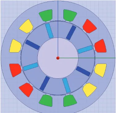
permanent magnets, and a smaller flux concentration. The chosen rotor can be seen on Figure 3.
The number of poles is then determined by the number of magnets in the rotor. In order to have a balanced three-phase machine, the possible pole numbers with 12 slots are 4, 8 and 10 (with 2 or 6 poles the flux variations in the coil would be zero because of rotor/stator symmetry). The associated winding factors are 0.5, 0.866 and 0.966 [4]. The existing motor has 6 poles. We choose an 8-pole rotor in order to have a good winding factor to have a higher torque, to minimise the mass. The chosen rotor is represented on Figure 3. The magnets are represented in dark or light blue depending on their magnetisation orientation, and the three stator phases are coloured in yellow, green and red. The big round hole in the center is the non-magnetic shaft.
Figure 3: 12slots/8pole chosen motor architecture
6 Machine design
The design presented here is a pre-design, prior to a proper optimisation process. A few singular steps of this pre-design and some choices made are highlighted and explained. The aim of this study is to assess the feasibility, the advantages and drawbacks of the chosen architecture. If the design is considered valid, a proper optimisation will be done, and then a prototype built to validate the performances and especially measure the partial discharges in the winding.
6.1 Magnetic pre-design
The major design parameters of the existing machines are kept: length (58mm), outer diameter (130mm), airgap diameter (90mm). The stator (NO20 0.2mm Fe-Si sheet stack) and rotor material (M400-50A 0.5mm Fe-Si sheet stack) are kept. The current density is kept constant, since the cooling will be identical (air-forced cooling generated by the fan
itself): 9A/mm². The main design tool is the finite elements method simulation, Ansys Maxwell software is used. The design strategy begins with a magnetic design, adjusting the airgap length (0.6mm), the magnet length (18mm) and width (5mm), the yoke width (10mm) and the duct thickness (1mm) to have an acceptable magnetic flux density distribution in the iron without current, with a maximum of 1.3T. The duct thickness is determined by a mechanical calculation. The magnetic flux density without current is represented on Figure!4.
Figure 4: no-current magnetic flux density
6.2 Airgap and slot adjustement
The machine back electromotive force is then simulated with a single turn winding, to adjust the back-EMF shape. The effect of the pole shoe width on the back-EMF is simulated on Figure 5 below.
Figure 5: back-EMF shape depending on the pole shoe length This figure highlights that the longer the pole shoe, the longer the plateau phase of the back-EMF trapezoidal shape, which is better for 6-step control. However, with too long pole shoes, the winding insertion is too complicated during the manufacturing process. We choose here to have a slot opening that is half the slot width, 24° (angle), in order to keep enough space for winding insertion.
In order to improve the back-EMF shape, we choose to modify to increase the airgap length above the pole shoe edges. The rotor outer edge remains a circle, but the pole shoe
edges are brought away from the rotor, as can be seen on Figure 6.
Figure 6: pole shoes taken away from the rotor
The result of the simulation of the impact of this modification on the back-EMF shape is presented on Figure 7 below: taking away the pole shoes from the rotor improves the flatness of the plateau phase of the back-EMF.
Figure 7: back-EMF shape depending on the pole shoe edge additional distance to the rotor
The teeth width and slot width are adjusted to get a good compromise between copper losses and magnetic flux density (iron losses); the same width of 14mm is chosen. All the dimensions will later be optimized before the prototype is built.
6.3 Winding design
With the measurement of the single-turn back-EMF, the winding can now be adjusted. Each tooth is wound with 20 coil turns. The chosen slot fill factor is 0.5, the slot area is 176mm², so the copper wire is 4.4mm². The estimated phase resistance is 36m" (19m" in the existing motor). Aircraft machines are manually wound, so to ease the winding and insertion process for the worker the machine will be actually wound with seven 0.8mm wires in parallel. The smaller wires are indeed much easier to manipulate than the bigger wires.
7 Simulation results
7.1 Nominal speedThe motor is powered with a 540V dc bus IGBT inverter. The control mode is six-step voltage switching with no current regulation. The actual motor will include at least a current limitation by chopping for safety reasons. The simulation is
done at fixed speed at nominal point (15krpm), and the control angle is chosen to minimise the current ripple (to limit the first failure mode, IGBT fault). The figures 8 to 10 show the simulated back-EMF, torque, and currents.
Figure 8: back-EMF at nominal speed for the new design
Figure 9: Simulated torque at nominal speed and voltage
Figure 10: Simulated currents at nominal speed and voltage for the new design
The back-EMF shape is trapezoidal, but the plateau phase width is only 60°, smaller than the optimal 120° required. This element can be improved in the final optimisation. Its maximum value is 240V, twice the maximum value of the existing motor, because the DC bus voltage has doubled. The existing motor has a quasi-sine back-EMF. The torque ripple increases to 18%, due to the use of concentrated winding, which remains acceptable. The current ripple is 15%, and its root mean square 29A. The total copper losses are 90W, compared with 148W in the existing machine. The airgap magnetic flux density is higher thanks to flux concentration and the absence of magnet retaining band, so less current is required to produce the rated torque, leading to lower copper losses.
The no-load torque of the new design is ±0.8Nm, four times higher than in the existing motor. This is due to the concentrated winding architecture, which has a naturally higher no-load torque.
The iron losses of the existing machine are 0,5kW. The iron losses of the new design, simulated with the Bertotti technique, are 0,8kW. This increase is due to the higher pole number, which has been chosen in order to balance the radial The motor efficiency at nominal point will then decrease from 93% to 91%. The thermal equilibrium of the new motor will have to be checked. A comparison with the 4-pole machine performances will be done in a further study, in order to assess the best motor parameters.
7.2 Slow speed
The BLDC six-step control mode can be tricky to implement for high speed machines, especially when the inductances are high. L#I can indeed not be neglected compared with the electromotive force at higher speeds [7]. The double layer concentrated winding is a high inductance design, so the compatibility with fixed control angle six-step control at every speed has to be checked. The simulated motor inductance was 1mH, ten times higher than the inductance of the existing motor (100!H). We have simulated the motor at 300rpm (fixed speed) with a lower voltage of 12Vdc (representing current limitation) and the same control angle: the current and torque results are presented on Figures 11 and 12.
Figure 11: simulated torque at 300rpm
Figure 12: simulated currents at 300rpm
The current shape at small speed is good, there is no control issue. We can see that the demagnetization following phase commutation is shorter than at nominal speed, because of the
smaller L#. The 300rpm simulated average torque is 6,7Nm, the torque ripple 28%, the current effective value 23A and the current ripple 22%. The machine control is less optimal than at nominal speed, but the difference is acceptable. L#I at nominal speed is 66V and the electromotive force is 240V at high speed, so it is logical that the optimal control angle shift between low and high speed will be small. This allows the usage of the high speed optimal control angle at all speeds.
8 Conclusions
The adaptation of an existing airliner fan motor to an HVDC electrical network has lead us to choose a single layer concentrated winding, in order to reduce the electrical constraints in the winding and the partial discharges issues. A flux concentration 8-pole rotor has been chosen, in order to maximize torque output. The BLDC motor is powered by a six-step inverter.
The newly designed motor has a higher torque and lower copper losses, but higher iron losses and torque ripple, because of the concentrated winding architecture. The efficiency is lower, so the thermal equilibrium of the new machine will have to be checked. The six-step BLDC control mode has also been validated at low speeds.
The new motor simulations point that the performances of the new architecture are interesting and worth continuing the investigation. Further works include a comparison with a four-pole motor and a proper optimisation process to tune the geometrical dimensions. A prototype will then be built to validate the new machine.
References
[1] E. Foch,. “Overview of MEA architectures and key technologies”. European conference on more electric aircraft 2015t, Feb 3-5, Toulouse, France
[2] M. Kaufhold, H. Aninger, M. Berth, J. Speck, M. Eberhardt, “Electrical stress and failure mechanism of the winding insulation in PWM-inverter-fed low-voltage induction motors”, Industrial Electronics, IEEE Transactions on , vol.47, no.2, pp.396-402, Apr 2000 [3] G.C. Stone, S.R.Campbell, H.G.Sedding, “Adjustable
speed drive surges: how they affect motor stator windings”, Electric Machines and Drives, 1999. International Conference IEMD’99, pp.207-209, May, (1999)
[4] F. Meier, “Permanent-Magnet Synchronous Machine with Non-Overlapping Concentrated Windings for Low- Speed Direct-Drive Applications”, PhD thesis, KTH, (2008).
[5] D. Ishak, Z.Q.Zhu and D.Howe, “Comparative Study of Permanent Magnet Brushless Motors with all Teeth and alternative teeth Windings”, Journal of Magnetism and Magnetic Materials, p el767 – el769, (2004).
[6] D. Ishak, Z.Q.Zhu and D.Howe,” “Permanent-Magnet Brushless Machines With Unequal Tooth Widths and
Similar Slot and Pole Numbers”, IEEE Trans. Ind. Appl., Vol.41, No.2, March/April, (2005).
[7] J. Hendershot, T. Miller. Design of Brushless Permanent-Magnet Machines, (Motor Design Books, 2010).
![Figure 1: single layer concentrated winding [4]](https://thumb-eu.123doks.com/thumbv2/123doknet/3155646.89921/3.892.498.782.534.609/figure-single-layer-concentrated-winding.webp)