To cite this version :
Bernot, Alix A high reliability natural convection
airliner actuator permanent magnet motor. (2016) In: ICEM 2016 (XXIIth
International Conference on Electrical Machines), 4 September 2016 - 7
September 2016 (Lausanne, Switzerland).
O
pen
A
rchive
T
OULOUSE
A
rchive
O
uverte (
OATAO
)
OATAO is an open access repository that collects the work of Toulouse researchers and
makes it freely available over the web where possible.
This is an author-deposited version published in :
http://oatao.univ-toulouse.fr/
Eprints ID : 18224
To link to this article :
DOI : 10.1109/ICELMACH.2016.7732504
URL : http://dx.doi.org/10.1109/ICELMACH.2016.7732504
Any correspondence concerning this service should be sent to the repository
administrator:
staff-oatao@listes-diff.inp-toulouse.fr
ΦAbstract -- This paper investigates the opportunity of
making a natural convection permanent magnet motor for an airliner high lift actuator. The motor is designed to have a maximum lifespan and reliability: removing liquid or forced air cooling removes a fault source. A winding with fully segregated phases is chosen to minimize phase-to-phase winding faults due to partial discharges that may appear at low pressures (high altitudes). A thermal analysis of the power that can be dissipated by natural convection and radiation is conducted. A two-pole surface-mounted permanent magnet motor is finally designed and optimized with a finite elements method analysis, leading to a motor ten times longer than its forced air cooling counterpart.
Index Terms— AC synchronous motor, high reliability, high efficiency, natural convection, surface mounted permanent magnet machine, thermal analytical model, two-pole motor.
I. INTRODUCTION
HE path towards more electric aircrafts is under way, expected to increase the airliner’s systems power density, efficiency and reliability, and to reduce the need for maintenance [1], [2], [7]. The Boeing 787 is the first bleedless airliner, with no hot air taken out of the motors for de-icing and cabin pressurization. The jet engine efficiency is thus improved.
The Airbus A380 was the first airliner to introduce electric-powered flight control actuators, alongside standard hydraulic actuators, pressured by a central pump driven by the jet engine. These are electro-hydraulic actuators, with a local hydraulic pump driven by an electric motor. The introductions of EHAs is stated to have led to a 500kg flight actuation system mass reduction, an electric cable being lighter that a hydraulic fluid pipe.
Electro-hydraulic actuators (EHA) are expected to eventually be replaced by electromechanical actuators (EMA), with the electrical machine directly driving the linear actuator. However, the failure of the electric drive may lead to a jamming of the actuator, condemning the control surface that cannot be moved even with a second parallel actuator. On the other hand, EMAs have several advantages over EHAs. They are much smaller and more efficient, and require less maintenance: no hydraulic fluid replacement, no leakage to be checked (an electric cable does not leak).
The aim of this paper is to investigate an electric machine designed for an airliner high lift actuator. The required machine lifespan is 100,000 hours functioning during 30 years, demanding an electrical machines with an MTBF A. Bernot is with IRT Saint-Exupéry, Toulouse, France (e-mail: alix.bernot@irt-saintexupery.com), on temporary assignment from Zodiac Aerospace, Auxerre, France.
(mean time between failures) of 200,000 hours. The main driveline of the designed machine is an increased reliability, so that it may be used in an EMA.
No centralized liquid cooling is allowed, in order to reduce the system mass and improve its reliability (no pipe). In order to remove the faults of the cooling fan, a natural convection motor is investigated. The low current densities necessary to achieve this goal will also reduce the winding thermal stress and hence winding faults.
The thermal specification is very demanding: 100°C maximum temperature housing in a 70°C ambient temperature (maximum temperature of non-pressurized aircraft zones). The machine has a rated speed of 12,000rpm, and a rated torque of 8.1Nm, during a few seconds, and it must sustain half the rated torque, i.e. 4.05Nm, at thermal equilibrium. The machine will therefore be designed to permanently withstand 4.05Nm at 12,000rpm.
The power electronics drive is supposed to be centralized in the aircraft electrical center, the PWM voltage being transported in cables several meters long. This configuration allows to switch the inverter supplying the motor in case of failure, limiting the actuator jamming to wire, electrical machine or mechanical fault. It is to be noted that some electromagnetic compatibility issues will appear with long distance PWM currents transportation.
If a high reliability motor leads to the absence of a second redundant motor and allows to use electromechanical instead of electro-hydraulic actuators, even a much bigger motor could lead to a gain at the system level. The investigation conducted in this paper will give an insight into the opportunity of building heavier naturally cooled motors in order to increase reliability.
II. ANALYTICAL THERMAL MODEL
The electrical machine is inserted in a black painted aluminum housing. The external dimensions of the housing are 130*130mm, corresponding to a standard flight actuator motor size (currently 128mm). The active parts of the stator are contained in a 126mm outer diameter cylinder (housing thickness 2mm). Some vertical fins, orthogonal to the rotation axis of the machine such as in [3] (radial finned housing), and contained between the 130*130mm outer box, are added to the housing.
actuator permanent magnet motor
Alix Bernot
Fig. 1. Radial finned housing of the motor (from [3])
The total power dissipation of the motor housing at the thermal equilibrium is calculated. It is assumed that the housing external temperature is uniform (the loss sources are roughly balanced both along the rotation axis length and angularly around it), and it is assumed that the housing external shape is a cuboid (no modelling of the fins), which length is L, height H and width W. This last assumption is rather conservative, since the fins should bring additional thermal dissipation.
The temperature of the stator iron and the copper will be higher than the temperature of the housing. The expected power dissipation will be low, and we suppose that the thermal coupling between the copper winding, the iron and the frame will be sufficient to ensure acceptable winding temperatures. Copper and iron temperatures will not be modelled.
Both the natural convection and the radiation are modelled. The radiation thermal flux is modelled by Stefan-Boltzmann law (1), with ε=0.9 the emissivity of the black paint of the housing, S=2·L·H+2·L·W+2·H·W the housing external surface, σ=5.67·10-8 W/m²K4 Stefan’s constant, T
hous
the housing temperature and Tamb the ambient temperature. It
is directly proportional to the motor housing surface. The view factor is equal to 1, leading us to (1):
P
rad=ε·S·σ·(T
hous4-T
amb4)
(1)
The natural convection is modelled separately on top-facing horizontal surface, bottom-top-facing horizontal surface and vertical surfaces. It is modelled with correlations involving Grashoff’s Gr (2) and Prandtl’s Pr (3) coefficients [4], [12].
Gr=g·H
3·∆
T/(µ²·T)
(2)
Pr=c
p·µ
/k
(3)
The Grashoff coefficient Gr depends on the height or width H of the considered surface, the gravity acceleration g=9.81m.s-2, the air viscosity µ=2.05·10-5 N·s·m-2 (at 340K),
the ambient air temperature T (in K) and ∆T (in K) the temperature difference between the disspating surface and the
air. The Prandtl number value is Pr = cp*µ/k = 0.72 for the
air (at 340K), it depends also on the air viscosity µ, thermal conductivity k = 0.026 W·m-1·K-1 and its specific heat
cp = 103 J·kg-1·K-1.
The flow will be laminar for Gr·Pr<108 for a vertical
surface, Gr·Pr<2·107 for a horizontal top facing surface. For a
130mm square section motor, Gr=4.49·106 and
Gr·Pr=3.23·106, so all the natural convection flows are
laminar. The correlations used to calculate the Nusselt number in laminar flows are (4) for the vertical surface, (5) for the top-facing horizontal surface, and (6) for the bottom-facing horizontal surface [12].
Nu=0.555(Gr·Pr)
0.25(4)
Nu=0.54(Gr·Pr)
0.25(5)
Nu=0.27(Gr·Pr)
0.25(6)
The Nusselt number is directly linked to the heat transfer coefficient h [W·m-2·K-1] (7):
Nu=h·H/k
(7)
H is the height or width of the considered surface and k is the thermal conductivity of the air [W·m-1·K-1]. Combining
(2) – (7) allows to calculate directly the heat transfer coefficient of the surface: h=1.5(∆T/H)0.25 for the vertical
surface, h=1.4(∆T/W)0.25 for the top-facing horizontal
surface, and h=0.7(∆T/W)0.25 for the bottom-facing
horizontal surface. The power dissipated by a face is then Pface=h·∆T·Sface.
A few examples of dissipated power by radiation and convection for different dimensions of the machine are calculated and presented in Table I below.
TABLEI
DISSIPATED POWER BY RADIATION AND NATURAL CONVECTION
H and W (mm) L (mm) Pconvection (W) Pradiation (W) Ptotal (W) 130 60 8 18 26 130 300 21 53 75 130 600 31 97 128 200 300 38 90 129
It is to be noted that the convection dissipated power is higher with long narrow shapes than with cubic forms. The dominant power dissipation mode is radiation, accounting for more than 70% of the total power dissipation. Unlike natural convection, which depends on several factors, radiation is a well-understood phenomenon, with accurate models. The accuracy of the analytical model should then be rather good, because the radiation thermal dissipation is an accurate figure. We expect the actual total power dissipation to be even greater, thanks to the presence of the radial fins.
III. FAULT SOURCES
The aftersales main fault sources, causing electrical motor returns are, ranked by decreasing order of occurrence:
- Inverter faults - Bearing faults
- Winding faults, short-circuit - Winding faults, open-circuit
The first fault source, the inverter fault, is not directly a motor fault, but may be caused indirectly by motor issues. It is typically a destroyed power transistor, due to high currents in the motor. This fault source can be addressed by power electronics design, which is not the subject of this study, and by introducing redundancies: several different inverters, located in the aircraft electrical center, can be connected to the same motor with long cables. If one inverter fails, it can be replaced by its neighbor to ensure the flight actuator can still be operational.
The second fault source, the bearing fault, can be due to common mode electric currents, or to unbalanced rotor forces on the shaft. The common mode currents can be reduced with detailed EMC studies and appropriate filters. In order to reduce the rotor radial forces, we choose a structure with many stator teeth per phase and per pole pair, in order to minimize the reluctance variation seen by the rotor permanent magnet. Using a balanced geometry with two pole pairs or more can also reduce the forces unbalance, but this would have increased the machine’s iron losses and increased further the size of the machine. This issue will have to be investigated in detail by simulating the rotor radial forces.
The third fault source, the winding short-circuit fault, can either be turn-to-turn, phase-to-phase or phase-to-mass. It is typically due to a damaged insulation during assembly, or because of high electric fields. The rise of voltages in the aircraft’s electrical networks increases steadily the second problem, as will be detailed in the next paragraph (partial discharges).
The fourth fault source, the winding open-circuit fault, is generally due to a soldered joint breakup. Special care has to be taken during the assembly process to ensure durable joints.
IV. PARTIAL DISCHARGES
The historic main electric network in the airliners is three-phase 115V 400Hz. In the early 2000s the variable frequency was introduced, with a 115V 360 to 800Hz network in the Airbus A380. The DC bus voltage of the inverter supplied by the rectified 115V network is 270V. The voltage has doubled in the Airbus A350 to 230V in part of the network, in order to reduce the cables mass, and Airbus is now considering 540V HVDC networks (rectified from 230V) [7].
This voltage rise generates higher electrical constraints on the winding insulation. One problem is the appearance of small discharges inside small gas bubbles in the winding insulations or between insulated conductors, called partial discharges. The partial discharges slowly damage the copper insulation, reducing the motor life expectancy. These partial discharges cannot appear at voltages below 320V peak, Paschen’s law threshold [5] - [7], and so do not appear with standard inverters . However, these partial discharges may appear with voltages generated by a 540Vdc inverter. This effect is worsened by the pressure drop at higher altitudes:
the pressure in non-pressurized zones of the aircraft can decrease down to 200hPa at 12,000m (40,000 feet). It is also worsened by the voltage rise and fall speeds in the switches which cause transient overvoltages (oscillations due to resonances), which increase with the improvement of semi-conductors technologies, especially the progressive introduction of wide-bandgap semiconductors such as Gallium Nitride and Silicon Carbide. With commutation times as low as 10ns and dV/dt up to 50kV/µs, these new materials allow power electronics with increased efficiencies, but introduce new challenges to the motor design.
The partial discharges appear mainly between two different phases, because there is the higher electrical constraint (with sometimes double the transistor’s dV/dt and the maximum voltage of the inverter between the two phases in certain commutation configurations). They can even also appear between two turns of the same wire when the time travel of the voltage wave through the copper wire is too slow compared with the inverter commutation time. The insulation between two turns of the same coil is generally limited, with only the copper wire enamel and a very thin layer of resin, favouring these discharges risks.
On the other hand, the copper to iron insulation is generally good with the usual techniques, combining insulating paper, wire enamel and resin, with lower partial discharges risks. Hence the main regions of the electric motor where these partial discharges are [5], [6], by decreasing order of probability:
- Inside the end windings, between two phases - Inside a slot, between two phases
- Between two conductors of the same coil
In the case of distributed windings, there is, most of the time, an overlap between the phases in the end windings. This is particularly at risk and is the most likely place of partial discharges if not correctly isolated.
The second place of partial discharges is when two phases share the same slot. Even with insulating paper separating them, the high voltage difference and high dV/dt, creating overvoltages, may lead to partial discharges between the phases.
The third place is between typically between the first and the last turn of the same coil, when dV/dt is the main aggravating factor. The voltage rise time of 50kV/µs achieved with SiC transistors can lead to an uneven rise of the electrical field near the copper wire, with up to 80% of the voltage located in the first turn at some point. This may lead to partial discharges between the first and the last turn if they are somewhere located next to each other.
In order to minimize the first and second partial discharges preferred sources, the winding proposed in the paper will have segregated phases that never overlap.
V. CHOSEN ARCHITECTURE
A. Stator
The chosen architecture is a surface-mounted permanent magnet synchronous machine, fed with a sinusoidal voltage
(Brushless AC machine). Surface-mounted permanent magnet machines are very common in the aerospace industry, thanks to their high power density and low inertia [7].
A two-pole machine is chosen, in order to reduce iron losses. A high number of slots per phase is also chosen, in order to reduce rotor radial forces and torque ripple, and to improve the back-EMF shape, which is more sinusoidal than with tooth-concentrated winding. 12 slots per phase, 36 slots in total were chosen. The simulated winding has only one turn with 50% slot fill. The number of turns will later be adjusted to the motor voltage. The electrical frequency of the motor is 200Hz at the rated speed 12,000rpm.
The stator material is NO20 0.2mm Fe-Si thin sheets, which are very common in aerospace electric motors.
The three phases of the winding are fully segregated, so that the copper coil of a phase never touches the copper coil of another phase, in order to reduce the partial discharges risks. The phase-to-phase short circuit fault is then removed. The winding is presented on Fig. 2 below.
Fig. 2. Stator winding
B. Rotor
In order to minimize rotor losses, the rotor is also NO20 steel sheets, mounted on a central shaft.
The rotor permanent magnet is Samarium-Cobalt. The remanent magnetic flux density can be adjusted, with a maximum of 1.05T. The rotor’s magnetization is only along one axis, as presented on Fig. 3 below. This configuration is easier to manufacture than radial magnetization of the permanent magnets. It also allows sinusoidal back-EMF. The rotor permanent magnet can be split in several parts for ease of assembly if needed, or be kept solid. A carbon fiber retaining sleeve is added, in order to secure the rotor operation. Carbon has a high resistivity, strongly limiting the sleeve losses when compared to metal sleeves such as Inconel [8].
Fig. 3. Rotor magnetization VI. DESIGNED MACHINE
A. Design process
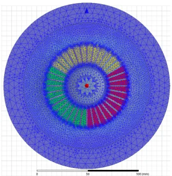
The machine is simulated with a finite elements analysis with Ansys Maxwell, in order to calculate torque and iron losses. The analysis is performed at the rated nominal speed 12,000rpm. Three-phase sinusoidal currents in phase with the back-EMF are fed into the windings. The current amplitude is adjusted to reach the rated continuous torque of 4.05Nm.
The iron losses are calculated in the stator and the rotor with a Bertotti model [9] of NO20, which was obtained with the magnetic flux density (T) vs losses (W/kg) at 400Hz provided by the thin sheets manufacturer [10]. The iron losses are then multiplied by 1.8 in order to account for the Bertotti model lack of precision, and influences not taken into account such as chopping or rotating fields.
The retaining sleeve and permanent magnets losses, mainly eddy current losses, are not calculated in the first optimization process, because it would lengthen the computation time. Since the electrical frequency is limited, 200Hz, we expect the rotor eddy current losses to remain small. They can be calculated after the first design process to verify the total losses. The mechanical and windage losses can also be calculated after the preliminary sizing process.
The machine is designed by minimizing losses, with the constraint that the copper and iron losses must remain below the analytical thermal model design dissipated losses. At a given length, several geometry dimensions are tested to minimize the losses at rated torque, and if the total losses is higher than the maximum allowed losses given by the analytical thermal model, a higher length is modelled, and a new design process is restarted.
B. Design results
After several rounds, a machine with the dimensions on Table II had lower copper and iron losses than the analytical model allowed thermal losses.
TABLEII
DIMENSIONS OF THE THERMALLY SUCCESSFUL OPTIMIZED MACHINE
Rotor radius 19mm Tooth length 21mm Tooth width 1.8mm Magnet width 8mm Magnetic airgap 2mm Slot opening 1mm External radius 63mm Active length 600mm Permanent magnet Br 0.65T
Current density 1.7A/mm²
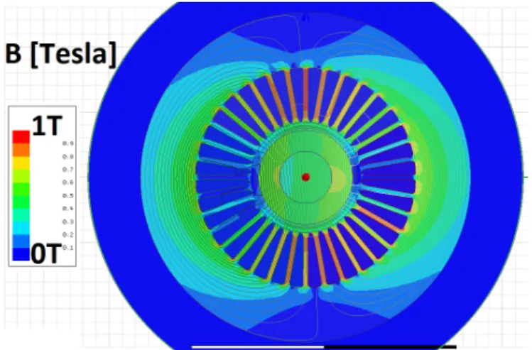
The maximum magnetic flux density without current is below 900mT, as represented on Fig. 5 below. The maximum magnetic flux density at rated current is 1.05T, as represented on Fig. 6 below. The maximum back-iron magnetic flux density is 550mT. These low magnetic flux densities ensure low losses.
Fig. 5. Magnetic flux density without current
Fig. 6. Magnetic flux density at rated nominal continuous torque The simulated no-load core losses are 34W, and the simulated rated torque iron losses are 35W, rounded at 63W with the 1.8 coefficient to account for Bertotti model lack of precision. The iron losses variation with the rotor angular position is only around 1%, thanks to the high number of teeth per phase (12). The iron losses density is represented on Fig. 7 below: the maximum loss density is 70W/L in a tooth. The iron losses are roughly evenly split between the stator back iron and the teeth.
Fig. 7. Iron losses density at rated nominal continuous torque The copper losses at 150°C copper temperature are 61W, with a current density of 1.7A/mm². This very low current density also allows for low losses, necessary to be compliant with natural convection.
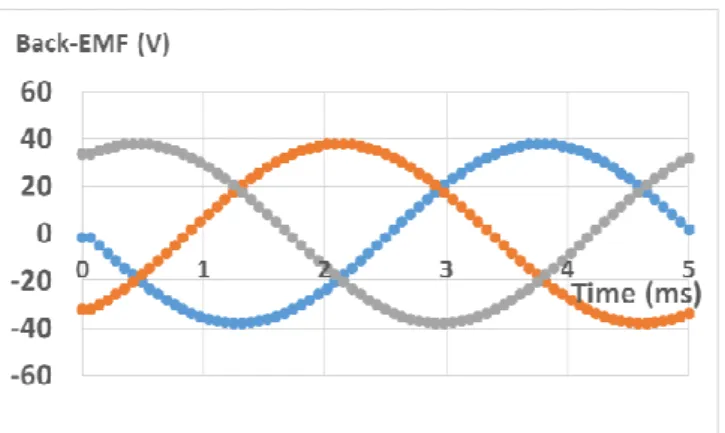
The peak torque without current is 700µNm, and the torque ripple is 1.5mNm at 4.05Nm output torque, less than 0.5%. The back-EMF of the three phases are sinusoidal, as can be seen on Fig. 8. All these features are due to the rotor diametral magnetization and the high number of teeth per phase.
Fig. 8. Magnetic flux density without current
C. Other losses
The windage losses in the airgap can be estimated with a model of a rotating cylinder in (8) [11].
P
w=2π·ω²·µ·R
3·
L/e
(8)
µ is the air viscosity, e the mechanical airgap thickness (1mm considering a 1mm thick retaining sleeve), R the rotor external radius (19mm), ω the angular velocity of the rotor (1256 rad/s) and L the rotor length (600mm). This leads to estimated windage losses of 0.83W, which is negligible compared to the 60W of iron and copper losses.
The mechanical losses (especially bearing losses) and the magnet losses are not estimated, but expected to be between 50W and 100W. The total calculated losses are 125W, and the estimated dissipated losses in the 600mm long housing is 128W, without accounting for the dissipation of the fins. The total losses will be higher because of the non-calculated losses, and the total dissipated power will also be higher thanks to the fin, so the total estimation should be fair. This has to be confirmed by the means of detailed thermal simulation, losses in the magnet computation and later by the building of a prototype.
VII. CONCLUSION
A natural convection machine has been designed (preliminary sizing) to comply with the strict specification of 100°C maximum housing temperature in an ambient air temperature of 70°C. The motor efficiency at the continuous rated torque (4.05Nm) is 97.4%, without taking into account mechanical and rotor losses. The motor active length is 600mm to be able to comply with the thermal dissipation of the housing, a rough and optimistic estimation. This machine would weigh more than 50kg, which is not acceptable, so the design or the specification has to change.
In comparison, a forced convection machine with the same specification would have an active length of 60mm, with an efficiency around 92-93% (classical aircraft electrical motors currently available), ten times smaller and lighter.
The designed natural convection machine appears to be long and heavy, in part because of the very demanding specification. Relaxing for instance the maximum housing temperature to 150°C would lead to an active length around 150mm, with 160W dissipated in the 130mm diameter housing according to the thermal analytical model, which
would be more acceptable. However, this would lead to much higher winding temperatures, risking a deterioration of the winding reliability. Some high temperatures winding will then have to be investigated.
The chosen segregated winding also has an influence on the torque density: changing the winding to a diametrical winding doubles the back EMF and the torque because more flux crosses the winding, leading to an additional 30% decrease in the motor length at constant external temperature. This winding change would however require a winding design allowing reinforced insulation where the end windings overlap, and a special care in this area.
Applying conservative design rules, in terms of dissipation mode, temperature and winding insulation has lead us to the preliminary sizing of a very long and heavy machine. The next step is now to change the specification and to explore new designs without decreasing the reliability, to reduce the motor length to around 100mm, an acceptable size for an airliner actuator. An analysis will then be able to be conducted at the system level, to verify if the introduction of natural convection electrical machines allows a gain, with the possibility to use electromechanical actuators for flight control. The motor reliability and availability will have to be calculated in detail for this analysis. Finally the motor will have to be finely tuned, simulating in detail all the losses and temperatures, and a prototype built to verify the assumptions.
VIII. REFERENCES
[1] E. Foch, "Overview of MEA architectures and key technologies"
European conference on more electric aircraft 2015, Feb 3-5,
Toulouse, France
[2] A. Boglietti, A. Cavagnino, A. Tenconi and S. Vaschetto, "The safety critical electric machines and drives in the more electric aircraft: A survey" 35th IEEE IECON, 2009, p2587-2594
[3] D. A. Staton, E. So, "Determination of Optimal Thermal Parameters for Brushless Permanent Magnet Motor Design", Industry
applications conference, 33rd IAS annual meeting, 1998, pp. 41-49
[4] D. A. Staton, A. Cavagnino, "Convection heat transfer and flow calculations suitable for electric machines thermal models", IEEE
Trans. Industrial Electronics, vol. 55, pp. 3509-3516, Oct. 2008.
[5] M. Kaufhold, H. Aninger, M. Berth, J. Speck, M. Eberhardt, "Electrical stress and failure mechanism of the winding insulation in PWM-inverter-fed low-voltage induction motors", IEEE Trans.
Industrial Electronics, vol.47, no.2, pp.396-402, Apr 2000
[6] G.C. Stone, S.R.Campbell, H.G.Sedding, "Adjustable speed drive surges: how they affect motor stator windings", International
Conference on Electric Machines and Drives, IEMD’99, pp.207-209,
May 1999
[7] W. Cao, B. C. Mecrow, G. J. Atkinson, J. W. Bennett, D. J. Atkinson, "Overview of electric motors technologies used for more electric aircraft", IEEE Trans. Industrial Electronics, vol. 59, pp. 3523-3531, Sept. 2012.
[8] S. Li, Y. Li, W. Choi, B. Sarlioglu, " High Speed Electric Machines – Challenges and Design Considerations", International Conference on
Electrical Machines, ICEM’14, pp2549-2555, 2014
[9] G. Bertotti, "General properties of power losses in soft ferromagnetic materials", IEEE Trans. Magnetics, vol.24, no. 1, pp621-630, Jan. 1988
[10] Available online at:
http://cogent-power.com/cms-data/downloads/NO20.pdf
[11] L. A. Dorfman, "Hydro-dynamic Resistance and the Heat Loss of Rotating Solids", Oliver and Boyd Ltd., 1963
[12] F. P. Incropera, D. P. DeWitt, T. L. Bergman, A. S. Lavine, "Fundamentals of heat and mass transfers", 7th edition, Wiley, 2011
IX. BIOGRAPHY
Alix Bernot graduated from the École Polytechnique, Palaiseau, France in 2009 and obtained his PhD on SMC transverse flux PM machines from CentraleSupélec, Gif-sur-Yvette, France in 2015.
He has worked 4 years as an electrical motor designer for Francecol technology, France, and is currently an electrical machines researcher at Zodiac Aerospace, Auxerre, France, on temporary assignment at IRT Saint-Exupéry, Toulouse, France.
His research interests are permanent magnet electrical machines design and modelling, and iron losses in soft magnetic materials.
![Fig. 1. Radial finned housing of the motor (from [3])](https://thumb-eu.123doks.com/thumbv2/123doknet/3104158.88065/3.892.88.421.89.347/fig-radial-finned-housing-motor.webp)