Any correspondence concerning this service should be sent to the repository
administrator:
[email protected]
O
pen
A
rchive
T
OULOUSE
A
rchive
O
uverte (
OATAO
)
OATAO is an open access repository that collects the work of Toulouse researchers and
makes it freely available over the web where possible.
This is an author-deposited version published in:
http://oatao.univ-toulouse.fr/
Eprints ID: 16237
To cite this version:
Pommier-Budinger, Valérie and Budinger, Marc and Tepylo, Nick
and Huang, Xiao Analysis of piezoelectric ice protection systems combined with ice-phobic
coatings. (2016) In: 8th AIAA Atmospheric and Space Environments Conference, AIAA
AVIATION Forum, 13 June 2016 - 17 June 2016 (Washington, United States).
To link this document:
http://dx.doi.org/10.2514/6.2016-3442
Analysis of piezoelectric ice protection systems combined with ice-phobic coatings 1
Analysis of piezoelectric ice protection systems combined
with ice-phobic coatings
Valérie Pommier-Budinger1
Université de Toulouse, Institut Supérieur de l'Aéronautique et de l'Espace, 31055 Toulouse, France
Marc Budinger
2Université de Toulouse, Institut Clément Ader, INSA Toulouse Toulouse, 31077, France
and
Nick Tepylo
3,Xiao Huang
4Carleton University, Dept. of Mechanical and Aerospace Engineering, Canada
Abstract: The aeronautics industry is looking for ice protection systems consuming less energy. Electromechanical and especially piezoelectric solutions are a promising area of research for reducing average consumptions. This article provides an analytical model of a simple structure to assess the power and voltage required to obtain the delamination of the accumulated layer of ice at the support/ice interface. This model also allows analyzing the impact of the resonance frequencies used for supplying piezoelectric actuators on the tensile stress into PZT materials. Finally, this article assesses the effect of different ice-phobic coatings combined with piezoelectric ice protection systems. Experimental measurements of ice adhesion for different ice-phobic coatings allow evaluating the shear stress at which ice is detached from the surface. These results are then used to estimate - thanks to the proposed analytical model - the additional gain of power that would be provided by the use of such coatings.
I. Context of the study
Ice accumulation on aircraft affects energy consumption, causes mechanical failures and increases safety hazards in most cases. To prevent frost, conventional protection systems use either thermal, electro-thermal or pneumatic solutions that consume energy, or chemicals that require large volumes of fluids and induce environmental issues and potential damage to the treated parts.
The aim of this study is to investigate a technology that combines a piezoelectric deicing system with an ice-phobic coating. The main expected impacts of combining these technologies are the decrease of the energy consumption and the reduction of environmental issues.
Regarding electric deicing systems, electro-thermal and electro-impulse technologies are already implemented on aircraft but studies are currently ongoing to propose new solutions that consume less energy or have less bulky power supplies. Among these studies, the de-icing systems based on piezoelectric systems are a subject of growing interest1..17. The principle is to apply vibrations that create shear stresses at a higher level than the shear stress required to lead to the delamination of the ice accumulated on the structure. Different frequency ranges have been investigated: low frequencies1..6 (Hz), high frequencies7..15 (kHz) and waves16,17 (MHz). Different
1 Associate Professor, DCAS/ISAE, [email protected]
2 Associate Professor, INSA/ICA, [email protected], corresponding author 3 Master student, MAE/Carleton University, [email protected]
Analysis of piezoelectric ice protection systems combined with ice-phobic coatings 2 technologies of actuators have been tested (Figure 1): piezoelectric ceramics, piezocomposite and Langevin transducers that are pre-stressed piezoelectric actuators. All these investigations are showing promising results. In this paper, we will first present a methodology to assess different architectures of piezoelectric deicing systems. This method allows computing the vibration magnitude that allows the required level of shear stress to be reached, the consumed current and voltage and thus the required power. Regarding the coatings, we propose in this study to investigate the ice phobic characteristics of two coatings proposed by Carleton University: ETFE plasma sprayed coating and a commercially available silicone based coating R-2180. As a first step of characterizing the coatings, the study will focus on the ability of these coatings to decrease the shear stress required to break ice/substrate bonding. The article will then present an analysis of the benefits of coatings to lessening the power of piezoelectric deicing systems.
Figure 1 – Technologies of piezoelectric actuators (ceramics, piezocomposite, Langevin) II. Main design drivers and modeling assumptions
This section summarizes the main drivers and modeling assumptions to be considered for the design of a piezoelectric deicing system.
Concerning the ice, the inputs required to assess architecture of piezoelectric deicing systems are: - The roughness of the structure on which ice accumulates
- The type of ice
- The thickness and the shape of ice
All these information enable the computation of the shear stress required to cause ice delamination. In the last section of this paper, measurements of shear stress with on bare samples and on samples with ice-phobic treatments are performed. We then assume a reference shear stress 𝜏𝑠ℎ𝑒𝑎𝑟 of 0.5MPa if the structure is not polished nor coated by an ice-phobic treatment; this value is consistent with results published by Petrovic18. In our computation, the ice is 2mm-thick and is uniformly spread on the structure.
The main drivers for the design of piezoelectric deicing systems are: - The dimensions of the substratum to protect
- The type of actuators (piezoelectric ceramics, piezocomposite, Langevin transducers) - The number and locations of these actuators
- The frequency range of use of these actuators with different types of mode and a limited number of resonance frequencies.
The models proposed in this work will be developed on plate considered as beam pinned at both ends. These boundary conditions enable to develop analytical equations. Two types of actuators are considered: piezoelectric ceramics and piezocomposite. However the proposed methodology could be applied to other types of piezoelectric actuators with use of finite elements simulations. The number of actuators will be fixed and positioned at the most efficient locations, that is to say where the stresses in the structure are maximal. For our study case, it corresponds to the center of the beams or plates, at the anti-nodes of resonance. At last, this work will focus on the frequency range [0, 30 kHz] and the main driver considered in this work is the resonance frequency used to lead to ice delamination.
The operational limits to be examined to ensure a good design and functioning of the piezoelectric deicing systems are:
- Mechanical de-icing: shear stress interface adhesion, tensile stress of ice. These values allow ensuring that ice delamination occurs.
- Actuator: voltage and mechanical stress. These values are required to ensure the good functioning of the actuator without damage.
- Power electronics: power, voltage, current. Voltage and currents are important values for the design of the power electronics and the power is a key driver in the selection of the resonance frequency for the design of low-consumption ice protection systems.
Analysis of piezoelectric ice protection systems combined with ice-phobic coatings 3 Concerning mechanical de-icing, we will focus mainly here on the shear stress and the vibration magnitude enabling to get a minimal value (given earlier in this section). Concerning the actuator, the applied voltage should not exceed the maximum electric field that can be applied without depolarizing the ceramics: we employ only the cases where the voltages do not lead to the maximal electric field acceptable by the piezoelectric ceramics to be exceeded (400V/mm for high frequency applications). The mechanical stresses in the piezoelectric ceramics are computed for the voltages that can break the ice and we keep only the cases for which these stresses are lower than the maximal stresses allowable for the piezoelectric ceramics before fracture occurs (15 MPa).
The following section will present the modeling of the structure with ice and with the actuators at fixed positions in order to determine the stresses at the interface structure/ice and in the actuators. This model will be determined analytically here but could be realized using Finite Element results19. It is a dynamic model that must include the damping of the structure. This model allows computing (a) the amplitudes of the vibrations that can create the required shear stress leading to the delamination of the ice on the structure and (b) the voltages corresponding to the required amplitudes of vibrations for different resonance frequencies on a frequency range. Like all resonant systems, the amplitudes of the vibrations coming from piezoelectric deicing systems depend strongly of the damping of the systems. In this article, the amplitudes of the vibrations are assumed to be linear with the quality factor Qm and this factor is assumed to be equal to 100 for the preliminary assessment of the
architectures (mean value for metallic structure). Experimental tests confirm this order of value even with ice accumulation.
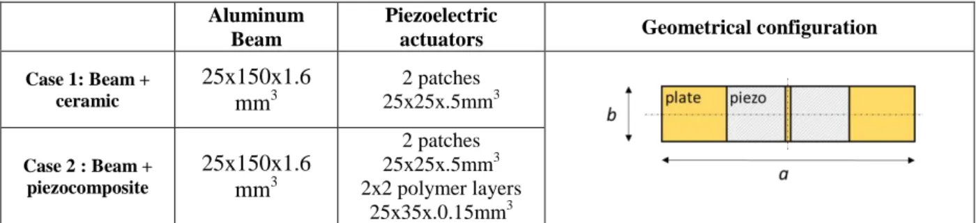
All the study cases with the characteristics of the substratum and of the piezoelectric actuators are described in Table 1.
Aluminum Beam
Piezoelectric
actuators Geometrical configuration
Case 1: Beam + ceramic
25x150x1.6
mm
3 2 patches 25x25x.5mm3 Case 2 : Beam + piezocomposite25x150x1.6
mm
3 2 patches 25x25x.5mm3 2x2 polymer layers 25x35x.0.15mm3Table 1 – Study cases for the comparison of piezoelectric deicing systems architectures
III. Model to assess architectures of piezoelectric deicing systems
The samples are considered as beams because of their aspect ratio. To study these samples, an analytical model of beams beam pinned at both ends is first presented to establish the relation between the vibrations amplitude and the stress required for ice delamination. It will then be extended by an analytical of the electromechanical coupling in order to estimate the corresponding required voltage. In this section, numerical applications will be performed with the assumption of ice reference shear stress equal to 0.5MPa. The effects of ice-phobic materials will be analyzed in the next section.
A. Modal analysis (1D beam)
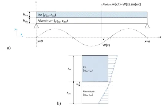
The vibrations generated by a piezoelectric actuator are more important around the resonance frequencies. The article20 compared the extensional and flexural modes, particularly their ability to generate shear stress at the ice-substrate interface. It shows that, for a given frequency and for a given displacement, the shear stress level at the ice-substrate interface is smaller for extensional than for flexural modes, while the tensile stress in the aluminum substrate is almost the same. Thus, to generate ice delamination while minimizing the displacement of the piezoelectric actuators, it is more interesting to excite flexural modes. Table 2 summarizes the relations between vibratory amplitude and stress. These equations are established using several assumptions: support and ice are considered as a thin multilayer beam (1D model), mode shapes are assumed to be identical to those of a uniform beam and boundary conditions are simply supported to enable simple analytical equations. Figure 2 shows the beam under study where:
x is the transverse position along the beam of length a ; n is the number of anti-nodes for the considered mode ;
Analysis of piezoelectric ice protection systems combined with ice-phobic coatings 4 is the angular frequency of the considered mode;
halu, hice, hn are respectively the thickness of the aluminum beam, the thickness of the ice beam and the
position of the neutral line for the flexural mode,
W(x) is the out-of-plane displacements magnitude for flexural modes;
calu , cice , ralu and rice are respectively the Young modulus and the density for the aluminum beam and the ice.
a)
b)
Figure 2 –Element of the beam under study
For flexural modes, the position of the neutral line hn can be obtained by assuming that the tensile force in a section is zero. This results in:
ℎ𝑛=1 2
𝑐𝑎𝑙𝑢ℎ𝑎𝑙𝑢2 − 𝑐𝑖𝑐𝑒ℎ𝑖𝑐𝑒2
𝑐𝑎𝑙𝑢ℎ𝑎𝑙𝑢+ 𝑐𝑖𝑐𝑒ℎ𝑖𝑐𝑒 (1)
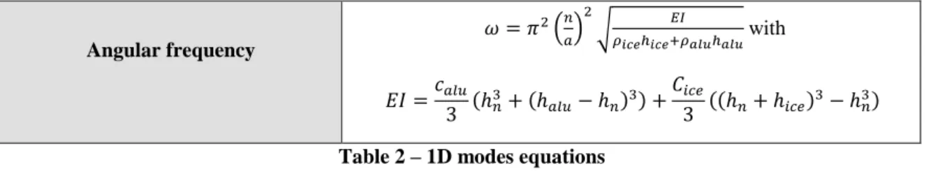
The equations of the peak out-of-plane shear stress were obtained by isolating an element of ice of thickness dx subjected to elastic forces, inertial forces and shear forces at the ice-substrate interface. The resonance frequencies were obtained by the Rayleigh method using the expression of the strains to estimate the kinetic and potential energies. These analytical equations show that for flexural modes, the maximum out-of-plane shear stress is located on the displacement nodes.
Displacement 𝑤(𝑥, 𝑡) = 𝑊(𝑥)𝑠𝑖𝑛 𝜔𝑡 = 𝑊0𝑠𝑖𝑛 𝑛𝜋𝑥 𝑎 𝑠𝑖𝑛 𝜔𝑡 𝑢(𝑥, 𝑡) = −𝑦𝜕𝑤 𝜕𝑥 = −𝑦𝑊0 𝑛𝜋𝑥 𝑎 𝑐𝑜𝑠 𝑛𝜋𝑥 𝑎 𝑠𝑖𝑛 𝜔𝑡 = 𝑈(𝑥)𝑠𝑖𝑛𝜔𝑡 Peak tensile strain
𝜀𝑥= 𝜕𝑈(𝑥) 𝜕𝑥 = 𝑊0𝑦 ( 𝑛𝜋 𝑎) 2 𝑠𝑖𝑛𝑛𝜋𝑥 𝑎 Peak ice tensile stress in ice
𝜎𝑥= 𝑐𝑖𝑐𝑒(ℎ𝑖𝑐𝑒+ ℎ𝑛) ( 𝑛𝜋 𝑎) 2 𝑊0𝑠𝑖𝑛 𝑛𝜋𝑥 𝑎 Peak tensile stress in aluminum
𝜎𝑥= 𝑐𝑎𝑙𝑢(ℎ𝑎𝑙𝑢− ℎ𝑛) ( 𝑛𝜋 𝑎 ) 2 𝑊0𝑠𝑖𝑛𝑛𝜋𝑥 𝑎 Peak out-of- plane shear stress at
the ice/aluminum interface 𝜏𝑥𝑧= 𝑐𝑎𝑙𝑢( 𝑛𝜋 𝑎) 3(ℎ 𝑎𝑙𝑢− ℎ𝑛)2− ℎ𝑛2 2 𝑊0𝑐𝑜𝑠 𝑛𝜋𝑥 𝑎
Analysis of piezoelectric ice protection systems combined with ice-phobic coatings 5 Angular frequency 𝜔 = 𝜋2(𝑛 𝑎) 2 √𝜌 𝐸𝐼 𝑖𝑐𝑒ℎ𝑖𝑐𝑒+𝜌𝑎𝑙𝑢ℎ𝑎𝑙𝑢 with 𝐸𝐼 =𝑐𝑎𝑙𝑢 3 (ℎ𝑛3+ (ℎ𝑎𝑙𝑢− ℎ𝑛)3) + 𝐶𝑖𝑐𝑒 3 ((ℎ𝑛+ ℎ𝑖𝑐𝑒)3− ℎ𝑛3) Table 2 – 1D modes equations
Area of validity of the modal analysis
The analytical formulations from the previous section were based on the assumption that the shear stress has a negligible effect on the rotation of the beam sections (Bernoulli assumption). In the case of short beams or for high-order resonance modes, this assumption is no longer valid. Timoshenko beam models could then be used. A comparison of the equations presented in Table 2 with finite element calculations shows that the analytical equations are valid up to 30 kHz. For higher frequencies, shear stresses generated by bending are over estimated, and the effort to generate the shear ice is thus under estimated. We therefore limit our study to a maximum frequency of 30 kHz.
B. Computing the amplitude vibration for de-icing
Minimal amplitude
To deice, it is necessary to achieve a minimal level of shear stress 𝜏𝑠ℎ𝑒𝑎𝑟 at the support/ice interface. The equations of Table 2 enable to link the vibration amplitude to this stress. The minimum 𝑊0 vibration amplitude to provide for a start of delamination in one localized point is given by:
𝑊0= 𝜏𝑠ℎ𝑒𝑎𝑟(𝑐𝑎𝑙𝑢(𝑛𝜋 𝑎) 3(ℎ 𝑎𝑙𝑢− ℎ𝑛)2− ℎ𝑛2 2 ) −1 (2) It is evident from this relationship that the vibration amplitude required for deicing decreases with the order and thus frequency of the resonant modes.
Increase of the de-icing surface
An increase of the vibration amplitude enables to ensure the rupture stress on a larger surface. Figure 3 shows the increase of the vibratory amplitude (relatively to the amplitude calculated with equation 2) in function of the ratio between the deiced surface and the total surface of the structure. This figure has been built by evaluating the ratio between the surface where the value of amplitudes is higher than the minimal amplitude required for starting deicing and the total surface of the structure.
Figure 3 – Increase of vibration magnitude versus the ratio of deiced surface
0 0.1 0.2 0.3 0.4 0.5 0.6 0.7 0.8 0.9 1 1.5 2 2.5 3 3.5 4 Ratio of surface R e la ti ve m a g n it u d e
Analysis of piezoelectric ice protection systems combined with ice-phobic coatings 6 C. Power calculation
The power is function of the effort and the vibratory velocity. The mechanical power required to activate the support can be expressed as:
𝑃 =1
2𝐹𝑚𝑎𝑥𝑣𝑚𝑎𝑥 (3)
Around a resonant frequency, the device can be likened to a spring-mass system. Modal masse and stiffness can be directly expressed by the following simple relationships:
𝑀 =(𝜌𝑎𝑙𝑢ℎ𝑎𝑙𝑢+ 𝜌𝑖𝑐𝑒ℎ𝑖𝑐𝑒)𝑎𝑏 2
𝐾 = 𝑀𝜔2
(4)
The effort at the resonance can be approximated by the relationship:
𝐹𝑚𝑎𝑥= 𝑀𝜔2𝑊
0
𝑄𝑚 (5)
and the power by:
𝑃 =1 2
𝑀
𝑄𝑚𝜔3𝑊02 (6)
with 𝑊0 the amplitude necessary for generating the sufficient shear stress to delaminate ice and 𝑄𝑚 the mechanical quality factor of the vibrating structure. Measurements allowed estimating this ratio to a minimal value of 100 for the beam under study covered with ice. For the rest of the article this value will be used while keeping in mind that the damping of the structure has a significant impact on the voltage and power to provide. Note: 𝑊0 is a function of the angular frequency 𝜔: it is proportional to 𝜔−
3
2. Consequently, with this model, the power is independent of the frequency.
D. Electromechanical coupling
Obtaining the supply voltage requires computing the electromechanical coupling between the resonant mode and the piezoelectric ceramic. Around a resonance mode, the reduced model of a structure20 with piezoelectric actuators can be made for one mode with a mechanical equation and an electrical equation:
V C Nq q NV Kq q D q M o C s (7) where q is the modal displacement, M the modal mass, K the modal stiffness, qc the electrical charge, V the voltage, Ds the modal damping, N the modal electromechanical coupling force factor, and Co the modal
turned-off capacity.
We assume here that the piezoelectric ceramics have little influence on:
• the mechanical parameters, i.e they provide little kinetic energy and little additional elastic deformation in view of their small volume compared to the volume of the entire plate with ice.
• the mode shapes which remain similar to those of Table 2.
In the further computations M and K are given by equations (4) and (5) and the displacement q of amplitude W0
is equal to the displacement of the neutral line on an antinode. The only remaining important parameter to calculate is thus the force factor N. This factor will be estimated here using the second equation by calculating the electrical charge qC on the electrodes for a zero voltage V=0 and a deformation q=W0. This force factor is
Analysis of piezoelectric ice protection systems combined with ice-phobic coatings 7 { 𝑻 = 𝒄𝑬𝑺 − 𝒆𝑬
𝑫 = 𝜺𝑺𝑬 + 𝒆𝒕𝑺 (8)
with T the stress vector, E the electric field vector, D the electric displacement field vector, S the strain vector, cE, e and
ε
S the piezoelectric coupling matrices.For the considered configuration electric field and electric displacement field vectors have only a non-zero component along y axis. They thus can be written here with scalar notation D and E. Finite element simulations show that for a zero voltage, the electric field E into the ceramic cannot be assumed to be constant. The absence of free charges enables to write that
D
/
y
0
thanks to Gauss theorem. The electric displacement field D is thus constant on the thickness of PZT ceramic, but is function of the position x (see axes in Figure 2). Since D is constant over the thickness of the ceramic, it is equal to its average value along the y axis. In the beam configuration the equation expressing D can be approximated by the following scalar equation:eS E
DS , (9)
where 𝑒 = 𝑒31+ 𝛾𝑒33 is the sum of 𝑒31 (strain along x axis) and 𝑒33 (strain along y axis) multiplied by 𝛾 (Poisson coefficient). By averaging equation (9) on the thickness of the ceramic, we get:
a n PZT n a h h h h h PZT PZT S S dy y x s h e h V S e E x D D ( ) 1 ( , ) (10) with hPZT the thickness of the PZT ceramic. For a zero voltage and strain of Table 2, equation (10) becomes:𝐷(𝑥) = 𝑒 (𝑛𝜋 𝑎 ) 2 𝑊0(ℎ𝑃𝑍𝑇 2 + (ℎ𝑎− ℎ𝑛)) 𝑐𝑜𝑠 ( 𝑛𝜋𝑥 𝑎 ) (11)
The integration of the electric displacement field on the ceramic surface gives the electrical charge useful for the estimation of the force factor:
𝑁 =𝑞𝑐 𝑞 = 2𝑏𝑒(ℎ𝑎− ℎ𝑛) ( 𝑛𝜋 𝑎 ) sin ( 𝑛𝜋𝐿𝑃𝑍𝑇 𝑎 ) (12)
Consequently, if the displacement required to cause ice delamination is known for a resonance mode, the voltage that generates this displacement is given by:
𝑉 ≈𝐹𝑚𝑎𝑥
𝑁 =
𝑀𝜔2𝑊 0
𝑁𝑄𝑚 (13)
Note: in equation (13), the impact of the quality factor is clearly visible. Among all the parameters of this relation, it is the most difficult to estimate by computation.
E. Results on the studied configurations
The two study cases of Table 1 are now assessed using the model proposed in the previous sections. The first study case consists of a plate with two massive ceramics (25x25x0.5 mm3) of type PZT 5H. Most defrost tests were carried out with this type of technology. It has the disadvantage of a risk of mechanical failure for too high vibration levels. Palacios noted this type of failure in his publications and reports12,13.
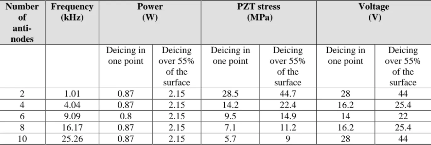
Table 3 shows the evolution of the characteristic quantities (frequency, voltage and power) leading to deicing for a beginning of delamination in one point and for a delamination over 55% of the surface. These values are computed for a shear stress of 0.5MPa and given for different modes (anti-symmetric) of resonances. Figures represent only half of the beam (length a/2). The voltage is minimal for the frequencies whose half-wavelength corresponds to ceramic dimensions. Table 3 also gives the stress in the ceramics while deicing. This stress is
Analysis of piezoelectric ice protection systems combined with ice-phobic coatings 8 close or exceeds the failure limits, about 15 MPa in traction, for bulk ceramics. This stress, however, decreases with frequency. The high rank modes seem therefore more interesting to avoid the mechanical failure of the actuators. The power required for deicing is approximately 232 W/m² for the beginning of delamination or 574 W/m² for 55% of the surface. This power is constant regardless of frequency with the simplified model proposed in this paper. Finite element simulations show slight increase of power consumption with frequency. This power is to be maintained during a short time. The average power of piezoelectric dicing systems is much lower than the average power of electro-thermal deicing system.
The study is now performed in the case of piezocomposites (2 ceramics 25x30x0.5mm3). In this technology, the PZT ceramics (2 ceramics 25x25x0.5mm3) are pre-stressed by two layers of rigid polymers (2 polymer coating 25x35x0.15mm3). Pre-stressing the PZT ceramics provides a better resistance to deformation (failure limit in traction is increased; further tests should allow determining this limit). Numerical computations with a Finite Element software show that the characteristic quantities for deicing are similar to those of Table 3. It means that the presence of the thin (0.15 mm-thick) and rigid (Young modulus 3 GPa) polymer layer does not degrade the performance of the piezocomposite compared to the bulk ceramics. Another conclusion is that the analytical formulation proposed to assess deicing systems based of bulk ceramics could be used to approximate the performance of deicing systems based on piezocomposites.
Number of anti-nodes Frequency (kHz) Power (W) PZT stress (MPa) Voltage (V) Deicing in one point Deicing over 55% of the surface Deicing in one point Deicing over 55% of the surface Deicing in one point Deicing over 55% of the surface 2 1.01 0.87 2.15 28.5 44.7 28 44 4 4.04 0.87 2.15 14.2 22.4 16.2 25.4 6 9.09 0.8 2.15 9.5 14.9 14 22 8 16.17 0.87 2.15 7.1 11.2 16.2 25.4 10 25.26 0.87 2.15 5.7 9 28 44
Table 3 – Deicing performance of a deicing system based on the use of the 2 bulk ceramics (study case 1)
IV. Analyses of piezoelectric deicing systems combined with ice-phobic coatings
Taking into account the benefit of the coatings to lessening the shear forces required to break the accumulated layer of ice, the architectures with the two technologies of piezoelectric actuators studied previously will be assessed once again and the gain in power consumption brought by ice-phobic coatings will be estimated. A. Ice-phobic materials
Coatings are generally classified as part of passive technologies to prevent ice accretion. Compared to chemicals, they have the advantage that they do not need to be applied timely and reapplied for each event22..32. Coatings can be employed alone or combined with active technologies allowing decreased power consumption. Two main coating types can lessen the effect of ice accumulation:
- ice-phobic materials that reduce the shear forces required to break the accumulated layer of ice on the solid surface.
- hydro-phobic materials that have a high tendency in repelling water due to the high contact angle between the water droplet and the solid surface thus eliminating the accumulation of water before water freezes and forms ice.
In the present study, we focus on ice phobic materials and investigate the ice phobic characteristics of two coatings: an in house plasma sprayed ETFE coating and commercial silicone R-2180 which have been applied using dipping and furnace curing process (Table 4). Both coatings have been applied onto an aluminum substrate and tested for ice adhesion strength using lap shear test setup.
Analysis of piezoelectric ice protection systems combined with ice-phobic coatings 9 Coating Application Method Supplier Coating appearance Coating Thickness (µm) Sample ETFE polymer Plasma
spray DuPont White 292
Silicone
R-2180 Dipping
Nusil
Technology Transparent 285
Table 4 – Application method and appearance of each coated material
B. Shear stress measurement Ice adhesion test
A freezing jig was manufactured to hold the coupons in place during the freezing process. The jig was designed such that the gap clearance between the top and bottom coupons remains constant at 0.100”. The jig measures 15” long by 5” wide and 0.5” thick and uses slots milled to a depth of 0.02” to keep the coupons aligned and can hold six test specimens at once (a total of 12 coupons) using the toggle clamps . A layer of parafilm was placed on top of the jig to prevent the coupons from sticking to the surface of the jig during the freezing process. Using a 1 mL syringe, 0.6 mL of deionized water was then injected into the hole in the lap shear joint (1” overlap) and the jig was placed in a freezer for 24 hours. This was done to ensure a complete transition of water to ice between the two coated surfaces. After 24 hours, each specimen was inspected to ensure complete formation of ice between the coated surfaces.
Ice adhesion test was carried out using a 100 kN Material Testing System (MTS) to measure the force required to break the lap joint. From the measured force, the shear stress at which ice is detached from the surface can be found and compared with literature. The frozen specimen was placed inside an insulated chamber and gripped by the MTS. The chamber kept the specimens at a temperature of approximately -15°C for the duration of the test. An axial displacement rate of 1 mm/min was used to pull the joint apart. The maximum load was then recorded for each sample and compared with previous experiments.
Ice adhesion strength
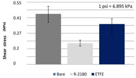
The lap shear test results are presented in Figure 4. Bare coupons required approximately 65 lbf to shear the ice formation on 1”x1” surface area. This indicates that the bare sand blast coupons exhibited a stronger adhesion to ice. As for ETFE and silicone R-2180, the forces required were approximately 52 lbf, and 27 lbf respectively. Based on these results, the silicone R-2180 requires about 65% less force to shear the ice layer between the samples when being compared to the bare aluminum. ETFE required 20% less force to shear the samples than the bare aluminum samples.
Figure 4 – Shear stress required to break the bond formed between the ice and substrate 0,00 10,00 20,00 30,00 40,00 50,00 60,00 70,00 80,00 Sh e ar str e ss (p si ) Bare R-2180 ETFE
1 psi = 6.895 kPa
0.55 0.41 0.27 0.2 0 (M P a)Analysis of piezoelectric ice protection systems combined with ice-phobic coatings 10 A total of six samples were shear tested for each type of the coatings. A large variation was observed in the results obtained from this study. However these variations in adhesion strength for each coating group are similar and also comparable that from previous tests conducted by other researchers23.
There are several variables that could not be controlled during the testing and lead to deviations in the results. Any deviation in terms of actual ice temperature would have impact on the shear strength. Another variable is the clamping pressure used during freezing. While the position of the clamps was constant for freezing each sample, the pressure exerted on each sample could be different due to the effects of surface tension exerted by the water. Since each surface is different in its surface tension, hydrophobic effects can vary significantly and cause a difference in the adhesion of ice to the sample.
C. Effects on piezoelectric de-icing system
The vibration amplitude 𝑊0 required to get ice delamination is function of the shear stress 𝜏𝑠ℎ𝑒𝑎𝑟. Using equations (2) and (6) for power computation, power can be expressed in function of this shear stress:
𝑃
𝐴𝑟𝑒𝑎 𝛼 𝜏𝑠ℎ𝑒𝑎𝑟2 (14)
It is noticeable that the power is proportional to the square of the stress:
In the same way one can show that stresses and strains are proportional to the shear stress. The use of ice-phobic coatings thus allows expecting significant gains in terms of power consumption but also in terms of mechanical stress for PZT ceramics or supply voltage. Figure 5 shows the evolution of these quantities in function of the shear stress at ice/aluminum interface.
a) Power vs shear stress
b) PZT tensile stress vs frequency c) Supply voltage vs frequency
Analysis of piezoelectric ice protection systems combined with ice-phobic coatings 11 V. Conclusion
This article presents an analysis of piezoelectric ice protection systems combined with ice-phobic coatings. Main design drivers of ultrasonic deicing systems have been introduced before developing an analytical model for beams beam pinned at both ends, covered with ice and actuated by bonded PZT. This model allows computing the power required for deicing. It also shows that high resonance frequencies enable reducing the tensile stress into PZT materials for a given shear stress at ice/structure interface and that the voltage is minimal for the frequencies whose half-wavelength corresponds to ceramic dimensions and. The last section of the article is dedicated to the ice-phobic coatings that reduce the shear forces required to break the accumulated layer of ice on a solid surface. The article shows that their use enables reducing the voltage and the PZT tensile stress that depend linearly of the shear stress and significantly the supply power (indeed power depends of the square of the shear stress).
References 1
Venna, S. V., Lin, Y. J., “In-Flight De-Icing Self-Actuating Wing Structures with Piezoelectric Actuators,” Proceedings of American Society of Mechanical Engineers/International Mechanical Engineering Congress and Exposition 2002, ASME Press, New York, 2002, pp. 237–245.
2
Venna, S. V., Lin, Y. J., “Development of Self-Actuating In-Flight De-Icing Structures with Power Consumption Considerations,” Proceedings of the American Society of Mechanical Engineers International Mechanical Engineering
Congress and Exposition 2003, ASME Press, New York, 2003, pp. 45–53.
3
Venna, S. V., Lin, Y. J., “Mechatronic Development of Self-Actuating In-Flight Deicing Systems,” IEEE/ASME
Transactions on Mechatronics, Vol. 11, No. 5, 2006, pp.585–592.
4
Venna, S. V., Lin, Y. J., Botura, G., “Piezoelectric Transducer Actuated Leading Edge De-Icing with Simultaneous Shear and Impulse Forces,” Journal of Aircraft, Vol. 44, No. 2, 2007, pp. 509–515.
5
Palacios, J., Smith, E., Rose, J., Royer, R., “Instantaneous De-Icing of Freezer Ice via Ultrasonic Actuation,” AIAA Journal, Vol. 49, 2011, No. 6, pp. 1158–1167.
6
Struggl, S., Korak, J., Feyrer, C., A Basic Approach for Wing Leading Deicing by Smart Structures, Sensors and Smart
Structures Technologies for Civil, Mechanical, and Aerospace Systems, Vol. 7981, 2011, p. 79815L-79815L-10.
7
Seppings, R., Investigation of Ice Removal From Cooled Metal Surfaces, Mechanical Engineering Department, Imperial College, London, 2006.
8
Palacios, J. L., Design, Fabrication, and Testing of an Ultrasonic De-Icing System for Helicopter Rotor Blades, Ph.D Thesis, The Pennsylvania State University, Department of Aerospace, May 2008.
9 Palacios, J. L., Smith, E. C., Rose, J., “Investigation of An Ultrasonic Ice Protection System For Helicopter Rotor Blades,”
Annual Forum Proceedings - AHS International 64th Annual Forum, Vol. 64, No. 1, 2008, pp. 609–618.
10
Palacios, J. L., Smith, E. C., Rose, J., Royer, R., “Ultrasonic De-Icing of Wind Tunnel Impact Icing,” Journal of Aircraft, Vol. 48, No. 3, 2011, pp. 1020–1027.
11
Palacios, J. L., Smith, E. C., “Dynamic Analysis and Experimental Testing of Thin-Walled Structures Driven by Shear Tube Actuators,” 6 th AIAA/ASME/ASCE/AHS/ASC Structures, Structural Dynamics, and Materials Conference, 2005, p. 1-14.
12
Overmeyer, A., Palacios, J., Smith, E., Royer, R., Rotating Testing of a Low-Power, Non-Thermal Ultrasonic De-icing System for Helicopter Rotor Blades, SAE Technical Paper, International Conference on Aircraft and Engine Icing and
Ground Deicing, Chicago, IL, No. 2011-38-0098, June 2011.
13
Overmeyer, A., Palacios, J., Smith, E., “Actuator Bonding Optimization and System Control of a Rotor Blade Ultrasonic Deicing System,” 53rd AIAA/ASME/ASCE/AHS/ASC Structures, Structural Dynamics and Materials Conference 20th AIAA/ASME/AHS Adaptive Structures Conference 14th AIAA, 2012, p. 1476.
14
Tarquini, S., Antonini, C., Amirfazli, A., Marengo, M., Palacios, J., “Investigation of Ice Shedding Properties of Superhydrophobic Coatings on Helicopter Blades,” Journal of Cold Regions Science and Technology, Vol. 100, 2014, pp. 50–58.
15
Strobl, T., Storm, S., Kolb, Thompson, D., Hornung, M., Thielecke F., Tobias Strobl, "Feasibility Study of a Hybrid Ice Protection System", Journal of Aircraft, Vol. 52, No. 6 (2015), pp. 2064-2076.
16
Ramanathan, S., Varadhan, V. V., Varadhan, V. K., De-Icing of Helicopter Blades Using Piezoelectric Actuators, Smart
Structures and Materials, Smart Electronics and MEMS, SPIE's 7th Annual International Symposium on Smart Structures
and Materials. International Society for Optics and Photonics, 2000, pp. 281-292.
17
Kalkowski, M. K., Waters, T. P., Rustighi, E., “Removing Surface Accretions with Piezo-Excited High-Frequency Structural Waves,” Proc. SPIE 9431, Active and Passive Smart Structures and Integrated Systems 2015, San Diego, California, March 2015.
18
J.J. Petrovic, Mechanical Properties of Ice and Snow, Journal of Material Science, Vol. 38, 2003
19
V. Pommier-Budinger, M. Budinger, ”Sizing optimization of piezoelectric smart structures with meta-modeling techniques for dynamic applications”, International Journal of Applied Electromagnetics and Mechanics, Vol.46(1), pp.195-206, 2014
20
Budinger, M., Pommier-Budinger, V., Napias, G., Costa da Silva, A, Ultrasonic Ice Protection Systems: Analytical and Numerical Models for Architecture Tradeoff, Journal of Aircraft, 1-11, 2016
Analysis of piezoelectric ice protection systems combined with ice-phobic coatings 12 21
Ikeda, T., Fundamentals of Piezoelectricity, Oxford Science Publications.
22
R. Jafari, R. Menini and M. Farzaneh, Applied Surface Science, 257, pp. 1540-1543 (2010)
23
EM 1110-2-1612, Engineering and Design – Ice Engineering, US Army Corps of Engineers, Department of US Army, Oct, 20, 2002.
24
S.L. Siva, B. Riegler, R. Thomaier and K. Hoover (P&W), A Silicone-Based Ice-Phobic Coating for Aircraft (a report).
25
R. Menini and M. Farzaneh, Elaboration of Al2O3/PTFE coatings for protecting aluminum surfaces. Surface and Coating Technology, pp.1941-1945 (2009).
26
R. Karmouch, S. Coude, G. Abel, and G. Ross, Icephobic PTFE coatings for wind turbines operating in cold climate conditions, Electrical Power & Energy Conference (EPEC), 2009 IEEE.
27
C. Ryerson, Assessment of Superstructure Ice Protection as Applied to Offshore Oil Operations Safety. pp.86-117(2009). http://www.arlis.org/docs/vol1/B/352898128.pdf
28
S.A. Kulinich, M. Farzanech, Ice adhesionon super-hydrophobic surfaces. Applied Surface Science, Vol. 255 (18), pp.8153-8157 (2009).
29
K. Philseok, et al., Liquid-Infused Naon-structured Surfaces with Extreme Anti-Ice and Anti-Frost Performance, ACS Nano, 6(8), pp.6569-6577 (2010)
30
H. A. Stone, Ice-Phobic Surfaces That Are Wet, ACS Nano,6(8), pp.6536-6540 (2012)
31
S. Ozba, C. Yuceel and H. Erbil, Improved Icephobic Properties on Surfaces with a Hydrophilic Lubricating Liquid, ACS Appl. Mater. Interface, 7(39), pp. 22067-22077 (2015)
32