OATAO is an open access repository that collects the work of Toulouse
researchers and makes it freely available over the web where possible
Any correspondence concerning this service should be sent
to the repository administrator:
[email protected]
This is a
n author’s version published in:
http://oatao.univ-toulouse.fr/25
598
To cite this version:
Mathis, Tyler S. and Kurra, Narendra and Wang, Xuehang and Pinto, David
and Simon, Patrice and Gogotsi, Yury Energy Storage Data Reporting in
Perspective—Guidelines for Interpreting the Performance of
Electrochemical Energy Storage Systems. (2019) Advanced Energy
Materials, 9 (39). 1902007. ISSN 1614-6832
Energy Storage Data Reporting in Perspective—Guidelines
for Interpreting the Performance of Electrochemical Energy
Storage Systems
Tyler S. Mathis, Narendra Kurra, Xuehang Wang, David Pinto, Patrice Simon,*
and Yury Gogotsi*
DOI: 10.1002/aenm.201902007
1. Introduction
The ever-increasing amount of atten-tion on electrochemical energy storage materials and technologies has brought an influx of new researchers to this field, which is undoubtedly one of the first steps toward progress.[1] The diverse
backgrounds and unique perspectives of new researchers can inspire and catalyze changes in conventional wisdom, which can lead to breakthroughs in an otherwise stagnated field. But it must be noted that this influx of fresh researchers is often a double-edged sword – newcomers to any scientific field will often be uninformed about the fundamental science, the con-ventions, and the methodologies that define the standards of the field, as well as the history that led the field to that point. Often this will result in experts of that specific field dismissing the work of new researchers outright, with little consideration for any possible scientific merit behind the work, simply because of improper data interpretation or the misuse of a calculation method by the researcher.
The field of materials for electro-chemical energy storage is no exception from this trend. Particularly notorious examples are, including but not limited to, nickel hydroxides, cobalt oxides, and nickel–cobalt oxides/ hydroxides.[2] Numerous studies on these materials are being
published each year, reporting specific capacitance values in the multiple thousands of Farads per gram that are simply ignored due to ways the authors interpret, analyze, and report their data. This is by no means a new issue, and it has yet to be resolved. To ensure the constructive progress of our field, we would like to once again bring the attention of researchers – and the reviewers that will judge the scientific foundations of their work – to the importance of correctly interpreting and reporting data for energy storage materials and devices.
In the following sections, we discuss the common mistakes committed by researchers when reporting performance metrics for energy storage materials, and how correctly recognizing the electrochemical characteristics of the specific electrode materials being studied can eliminate these mistakes. The
Due to the tremendous importance of electrochemical energy storage, numerous new materials and electrode architectures for batteries and supercapacitors have emerged in recent years. Correctly characterizing these systems requires considerable time, effort, and experience to ensure proper metrics are reported. Many new nanomaterials show electrochemical behavior somewhere in between conventional double-layer capacitor and battery electrode materials, making their characterization a non-straightforward task. It is understandable that some researchers may be misinformed about how to rigorously characterize their materials and devices, which can result in inflation of their reported data. This is not uncommon considering the current state of the field nearly requires record breaking performance for publication in high-impact journals. Incorrect characterization and data reporting misleads both the materials and device development communities, and it is the shared responsibility of the community to follow rigorous reporting methodologies to ensure published results are reliable to ensure constructive progress. This tutorial aims to clarify the main causes of inaccurate data reporting and to give examples of how researchers should proceed. The best practices for measuring and reporting metrics such as capacitance, capacity, coulombic and energy efficiencies, electrochemical impedance, and the energy and power densities of capacitive and pseudocapacitive materials are discussed.
T. S. Mathis, Dr. N. Kurra, Dr. X. Wang, Dr. D. Pinto, Prof. Y. Gogotsi Department of Materials Science and Engineering, and A.J. Drexel Nanomaterials Institute
Drexel University
3141 Chestnut St., Philadelphia, PA 19104, USA E-mail: [email protected]
Prof. P. Simon Université Paul Sabatier CIRIMAT UMR CNRS 5085
118 route de Narbonne, 31062 Toulouse Cedex 4, France E-mail: [email protected]
Prof. P. Simon RS2E FR CNRS 3459 Amiens, France
The ORCID identification number(s) for the author(s) of this article can be found under https://doi.org/10.1002/aenm.201902007.
emphasis of this tutorial will be on first distinguishing the correct charge storage mechanism and then reporting the appropriate performance metrics. Briefly, capacity/charge values should be reported for battery-like materials, and it is strictly advised to not report capacitance values for these mate-rials, as reporting capacitance for electrode materials with diffusion-limited, faradaic processes (battery-like materials) is meaningless. The importance of using integration formulas for calculating electrochemical performance metrics and the necessity of reporting the coulombic and energy efficiencies of energy storage devices are also discussed. Further, pos-sible misinterpretations of electrochemical impedance data and ways to correct such anomalies are discussed. Finally, we look at considerations to be made when trying to correctly estimate the capacitance of devices with apparent resistive losses, as is the case for paper and textile-based energy storage devices, which are becoming more popular and relevant in the literature.
2.
Distinguishing Capacitive/Pseudocapacitive
Systems from Battery-Like Materials
The most common mistake leading to errors in data reporting in the literature – in our opinion – is the incorrect classifica-tion of the electrode material being used (Scheme 1). The most straightforward way to avoid this is by determining the mechanism through which charge is being stored. The first question a researcher should ask is if the material stores charge through: a) a faradaic (electron-transfer) process, or b) solely by the accumulation of ions at an electrical double layer. As a first step toward correctly distinguishing the charge storage mecha-nism, scientists should simply look at the voltammograms and galvanostatic charge–discharge (GCD) responses of the mate-rial in question.[2] Any material with current versus voltage
curves (cyclic voltammograms, or CVs) containing a double-layer capacitor-like response will show a linear voltage versus time response (a triangular-shaped profile) d uring c onstant current charging/discharging (Figure 1a) and rectangular CVs (Figure 1d). In this case, the amount of charge stored varies linearly as a function of potential, and a single value of capaci-tance can be easily calculated and reported for capacitive energy storage systems. On the other end of the spectrum, a mate-rial with constant current charging/discharging curves with obvious plateaus (Figure 1c) or CVs that have intense, clearly separated oxidative and reductive peaks (Figure 1f), should be categorized as a faradaic, or battery-type, material. Unlike the case of capacitive charge storage, charge storage by battery-type electrodes follows a nonlinear relationship with the applied potential, which makes it unambiguously wrong to report capacitance for these systems. Capacitance can be used only when there is a linear relationship between charge and voltage, and the capacitance value should be a single constant value in the chosen potential window, any deviation from this behavior requires that integration be used to calculate the charge being stored or delivered.
Another characteristic feature that will aid in categorizing the electrode is by examination of the material’s intrinsic charge storage kinetics. Trasatti and co-workers proposed a method to
Tyler Mathis is currently a
Ph.D. candidate in the Drexel Nanomaterials Group under the mentorship of Dr. Yury Gogotsi. He joined Dr. Gogotsi’s research group in the Department of Materials Science and Engineering at Drexel University in 2015. He obtained his B.Sc. in Biochemistry and Molecular Biology from the University of California at Santa Cruz in 2015. His thesis research is focused on investigating the charge storage mechanisms of conductive 2D transition metal carbides for electrode mate-rials in electrochemical energy storage devices.
Patrice Simon is currently
a distinguished professor of Materials Sciences at Université Paul Sabatier, Toulouse, France and serves as Deputy director of the French network on electro-chemical energy storage (RS2E). He received his Ph.D. in 1995 from Ecole Nationale Supérieure de Chimie, Toulouse. He was appointed as Assistant Professor—Chair of Electrochemistry—at Conservatoire National des Arts et Métiers in Paris, and joint Université Paul Sabatier in 2001. His research activities are focused on the modification of material/elec-trolyte interfaces in electrodes for electrochemical energy storage devices, including batteries and electrochemical capacitors.
Yury Gogotsi is a Charles T.
and Ruth M. Bach Distin-guished University Professor in the Department of Mate-rials Science and Engineering at Drexel University. He also holds appointments in the Departments of Chemistry and Mechanical Engineering and Mechanics at Drexel University and serves as a Director of the A. J. Drexel Nanomaterials Institute. He served as an Associate Dean in the College of Engineering from 2003 to 2007. He received his M.S. (1984) and Ph.D. (1986) degrees from Kiev Polytechnic and a D.Sc. degree from the Ukrainian Academy of Sciences in 1995. His research group works on 2D carbides and nitrides (MXenes), nanostructured carbons, and other nanomaterials.
estimate the contributions of “inner” (diffusion-controlled) and “outer” (surface-controlled) surfaces to the total charge meas-ured using voltammetry[3]
T i o
q = +q q (1)
Where qT is the total charge, qi the charge at the inner
sur-face and qo is the charge at the outer surface. The foundation of
the method is that the instant storage of charged species (ions) at the outer electrode surface is independent of the scanning rate (nondiffusion-controlled), while charge storage at the inner surfaces is a diffusion-controlled process. Thus, the total meas-ured voltammetric charge (q(v)) could be expressed as a func-tion of scan rate (v) through the following equafunc-tion
1/2
q v
( )
=q∞+kv− (2)where kv−1/2 represents charge storage related to semi-infinite
diffusion, k is a constant, and q∞ is the charge stored at a high
scanning rate (v → ∞). The extrapolation of q to v = 0 gives the total charge (qT) while extrapolation of q to v → ∞ can obtain the
charge stored at the outer surfaces (qo).
Similarly, the relationship between response current (i) and the scan rate (v) is given by the sum of the contributions from the surface-controlled and diffusion-controlled currents, and can be described using the empirical formula[3,4]
capacitive diffusion
i i= +i =avb (3)
where “a” and “b” are adjustable parameters in the equation. Taking the logarithm of both sides of this equation yields
= +
i a b v
log log log (4)
If the value of b is 0.5, the current response (i) will be propor-tional to the square root of the scan rate (i ∝ v1/2, where v is the
scan rate in mV s−1) due to diffusion-controlled processes (if we are to assume a planar diffusion process). For b-values equal to 1, the current response will be linearly proportional to scanning rate (i ∝ v), which is characteristic of surface-controlled behavior. Typically, battery-like electrodes involve diffusion-controlled processes while capacitive and pseudocapacitive electrodes are associated with surface-controlled processes. Simply looking at the power law dependence of the current response (i) on the scanning rate (v) using the equation i = avb, allows for quick
determination of the electrode kinetics.[3,4] b-Values between
0.5 and 1 are a transition area from battery-like to capacitive-like responses, and though it is hard to define a sharp boundary, researchers should consider these intermediate values carefully. For instance, a spherical diffusion process would lead to a b value of 0.75.[5] If the b value is between 0.85 to 1, surface
reac-tions play a dominant role over diffusion-controlled reacreac-tions. The b value is highly dependent on number of factors such as potential, sweep rate, and charge storage mechanisms.
While classical battery and capacitor behavior are easily dis-tinguishable from one another, there is an increasing number of materials, including nanostructured materials (oxides, carbides, nitrides, conductive polymers, etc.) displaying elec-trochemical signatures that are neither purely capacitive nor purely faradaic,[6] which often brings confusion to researchers
during data analysis and reporting.
These “in between” materials have collectively come to be classified and treated as “pseudocapacitive” materials, which in some cases is an incorrect classification. That being the case, it is necessary to define what makes a material “pseudo-capacitive.” The concept of pseudocapacitance was originally defined by Conway in his seminal book, “Electrochemical Scheme 1. Illustration of the electrode processes occurring at a) electrical double-layer capacitive, b) pseudocapacitive, and c) faradaic electrodes.
Supercapacitors: Scientific Fundamentals and Technological Applications.”[7] In this text Conway explains how typical
pseu-docapacitive systems share similar electrochemical responses to typical capacitive materials, i.e., rectangular voltammograms, similar kinetics, and a linear dependence of charge stored versus the width of the operating potential window; however, pseudocapacitive charge storage is entirely faradaic in origin and therefore fundamentally different from typical double-layer capacitor-type materials. However, it is important to remember that there is not an absence of double-layer formation in fara-daic charge storage (including batteries), as all charge storage processes require the formation of an interface between the charge storing media and the electrode surface. Conway also emphasized that systems with prominent redox peaks that have no separation and highly reversible reactions occurring without phase changes – resulting in symmetrical CVs – should fall into the category of being pseudocapacitive (i.e., the b value should be close to 1). This definition (simplified for brevity) holds the guidelines by which all experts in the field interpret new mate-rials. As a practical example, a pseudocapacitive material will generally have the electrochemical characteristics of one, or a combination, of the following categories: I) underpotential deposition, II) surface redox pseudocapacitance, or III) intercala-tion pseudocapacitance.[8] It should be noted that “intercalation
pseudocapacitance” is different from the processes occur-ring in batteries, where intercalation pseudocapacitance describes redox reactions associated with ion intercalation
that are not accompanied by a phase transformation of the elec-trode material.[9]
There have been numerous methods proposed for estimating and distinguishing between surface and bulk redox contribu-tions toward the total charge stored by the pseudocapacitive material under study. Trasatti[3] and Dunn[4b] generalized
Con-way’s method for deconvoluting the contributions of capacitive (surface-controlled) and diffusion-controlled processes to the total current. Long et al. also demonstrated this process for dis-tinguishing between the pseudocapacitive and battery-like pro-cesses for the insertion of lithium into LiMn2O4.[10] Recently,
Donne and Forghani developed step potential electrochemical spectroscopy to separate the diffusion-limited process from the electrical double-layer contribution.[11] Simon and co-workers
proposed a general qualitative method called MUltiple Step ChronoAmperometry to minimize ohmic drop contributions, thus allowing electrochemical kinetics studies of pseudocapaci-tive electrodes.[12] In all cases, truly pseudocapacitive materials
will show the following: linear peak current responses versus scanning rate (i ∝ v), symmetric redox peaks with little to no separation (Figure 1b,e), highly reversible charge transfer, electrochemical impedance spectra, or Nyquist plots, typical of capacitive materials (see Section 5 and Figure 5), and charac-teristics that are indicative of a lack of phase changes during cycling. With these properties in mind, it should be clear why a material with the electrochemical response of Figure 1c (typ-ical of, for example, a nickel/cobalt hydroxide in potassium Figure 1. Archetypal electrical output behavior of three main types of electrodes, including a,d) electrical double layer, b, e) pseudocapacitive, and c,f) battery type. a–c) Schematic of galvanostatic charge-discharge profiles showing linear and nonlinear responses with time and d–f) corresponding CV profiles.
hydroxide electrolyte) should be classified as a battery-type material. Some conductive-polymer electrode materials show similar electrochemical characteristics to battery-type materials with large peak separations in their CVs, but no phase trans-formation occurs during the charging process. Hence, these materials, often termed redox capacitor electrodes, belong to neither the battery nor the pseudocapacitive category. However, the performance evaluation of a redox capacitor material should be the same as a battery-type electrode due to the similarity of their electrochemical responses.
Once a material class has been decided on, it then becomes pertinent to use the correct techniques and formulas for evalu-ating and reporting on the electrochemical performance of the material or system. In the following sections we will clarify when a particular formula is applicable to all materials/sys-tems, or when a formula may only be appropriate if certain conditions are met (e.g., capacitance), as well as the reasoning behind these decisions.
3.
Why Capacity and Charge Should be Employed
over Capacitance for Evaluating the Performance
of Battery-Type Electrode Materials
At the most fundamental level, the amount of charge stored (Q, in coulombs) in a dielectric capacitor is linearly propor-tional to the electric potential difference between the plates (V, in volts), as represented by Equation (5). The positive con-stant of proportionality C (in Farads), defined as the capaci-tance, describes the capability of the capacitive electrode to store a constant amount of charge in the given voltage range
Q CV= (5)
Experimentally, capacitance can be calculated from the slope of the discharge portion of a potential versus time curve (by con-vention, discharge refers to the delivery of stored charge) using a simple equation C = i/slope, where i is the applied current and the slope is equal to dV/dt (Figure 1a). Due to the charge storage mechanism associated with dielectric capacitors, this linear relationship between charge and voltage is the result of the physical electrostatic attraction of charges (linear dielectric response). Hence, capacitance (Farads) is the standard metric used for systems which exhibit linear charging responses to applied potentials, as is the case for the first and second genera-tions of capacitors, namely dielectric and electrolytic capacitors. Electrical double-layer capacitors (EDLCs) show orders of magnitude higher capacitance over the previous generations of dielectric and electrolytic capacitors due to the formation of molecularly thin Helmholtz double layers throughout the porous networks of carbon electrodes with high specific sur-face areas. The output electrical response of EDLCs resembles that of dielectric capacitors. However, surface functional groups on the carbon can lead to parasitic electrochemical reactions, causing deviations from ideal triangular charge–discharge profiles. As mentioned in the previous section, pseudocapaci-tive materials store charge through surface redox reactions and the output electrical response tends to resemble capacitive
behavior (Conway definition). Typical examples include MnO2
and RuO2, where continuous redox processes throughout the
operating potential window lead to CVs and charge–discharge profiles with capacitor-like behavior. It is recommended that capacitance be calculated by integrating the charge (Q) deliv-ered over the entire discharge (or charge) potential window, as shown by Equation (6), (instead of using an approximate charge value) to account for small deviations when properly calculating the average capacitance
1 d 1 2 C E V i V V
∫
ν = (6)In this case, E is the potential window (E = V2− V1, where
V2 and V1 are the bounds of the potential window), ν is the
scan rate, i is the discharge (or charge) current and dV is infini-tesimal changes in potential. Capacitance values for pseudoca-pacitive materials can be computed using Equation (6) if the requirements set out in Section 1 are met, in order to allow for comparison with state-of-the-art capacitive-type materials. How-ever, since the pseudocapacitive charge storage mechanism is faradaic by nature, the charge (capacity, in C g−1 or mAh g−1)
can, and should, also be calculated for the purpose of compar-ison with other redox materials.
Typically, cyclic voltammetry profiles for battery-type elec-trodes exhibit distinctive redox peaks that are clearly separated, with a negligible capacitive envelope that does not contribute significantly to the charge stored. Unlike capacitors, the charge being stored does not remain constant in the specified poten-tial window, but rather becomes more pronounced at certain potentials that are associated with the redox reactions occurring (Figures 1f and 2b). Therefore, capacitance is an invalid para-meter to assess performance as the charge is changing nonlin-early with potential and must not be used as high capacitance values are only reached within a very narrow voltage window. Charge storage values of these electrode materials must be solely reported in C g−1 or mAh g−1. The battery community has established guiding principles for calculating performance parameters and representing data appropriately.[13] Capacity, for
example, is reported strictly in terms of mAh g−1, which can be
easily calculated by dividing charge (C g−1) by a factor of 3.6. Reporting of GCD profiles should be done in terms of poten-tial (V) versus capacity (mAh g−1), which provides insight about the insertion/extraction potentials of charge compensating ions through the electrode material. Additionally, sloping and plateau regions in potential versus time curves are character-istic of battery-like materials (Figure 1c), and can be assigned to the formation of solid solutions and two-phase reactions, respectively.
As per the discussion above, it is important to identify the type of charge storage process associated with the electrode material and report the corresponding metrics for accurate esti-mations. For example, reporting capacitance instead of capacity for battery-type electrode materials will perpetuate inaccurate and misleading comparisons of performance. Here we are going to practically demonstrate why capacitance should not be used for battery electrodes by considering the example of a lithium iron phosphate (LiFePO4, LFP) electrode in LiPF6 in
electrolyte, which shows three different regimes in its poten-tial versus capacity plot (Figure 2a). From 4 to 3.6 V, there is a linear discharge profile with a capacitance value close to 0 F g−1 (LFP is a low surface area material); then from 3.4 to 3.2 V
a capacitance value of around 1866 F g−1 can be calculated, this value again becomes 0 F g−1 in the potential window of 3.2
to 2 V. From this simple demonstration of the misuse of the capacitance formula, it is very clear that if we were to report the capacitance of this material, it would be almost an order of magnitude higher than that of all carbon-based capacitive electrodes. However, a notable point to consider here is that the “capacitance” of the LFP electrode is only available in a 0.2 V range (from 3.4 to 3.2 V) of the total potential window (2 to 4 V, vs Li/Li+). This is completely unlike carbon EDLCs, where
the capacitance value remains almost constant over their entire operational potential window (typically, 2.5–3 V in organic elec-trolytes). Similar arguments can be drawn when considering the voltammogram of the LFP electrode (Figure 2b), in which pronounced current values are seen within a narrow potential window of 0.2 V. Further, if a researcher was to use this high value of capacitance (1866 F g−1) in combination with a voltage window of 2 V (instead of 0.2 V) when calculating energy den-sity using the standard formula of E = ½ CV2, they would
obtain an extraordinary energy density value of ≈1019 Wh kg−1, which is obviously unrealistic. However, by using a 0.2 V potential window with the same capacitance value, an accurate, and reasonable, energy density of 10.33 Wh kg−1 is obtained for the operating region of this material that we have treated as “capacitive.” From this intentional misuse of the formulas available for calculating charge storage, it should be clear how energy density values can be overestimated, by two orders of magnitude in this case, when inappropriate values of capaci-tance and potential are used. It should also be noted that the equation E = 1/2CV2 is not applicable here, and the results
calculated based on this equation are unreasonable as men-tioned previously. It cannot be stressed enough that before this equation is used that the concept of capacitance must not be overlooked.
For this demonstration we considered a classic battery material, LFP, as our electrode material. However, similar arguments are valid for other types of nanostructured bat-tery-type electrodes, as they will show similar GCD and CV profiles. Consequently, in these cases reporting capacitance
and energy densities should be done with caution. There are many articles published every year that report capacitance values exceeding 1000 F g−1 for nanostructured faradaic mate-rials, including Ni(OH)2, NiCo2S4, and Co(OH)2, which, to
put it simply, are wrong. This tutorial is not the first instance where the inaccuracy of evaluating the capacitance, instead of the capacity or charge, for such materials has been dis-cussed.[8] CVs for each of these materials have distinct redox
peaks with large peak separation and their GCD profiles have clear plateaus, which unambiguously classifies these as bat-tery-type materials. It may be argued that these materials are capable of operation at relatively high scanning rates or current densities when compared to conventional battery electrodes, however, they should be classified as high-rate battery-type materials rather than pseudocapacitive materials (as per the dis-cussion in Section 1). And if these high-rate battery materials are to be compared to capacitive or pseudocapacitive systems they should be tested at the rates that capacitive systems are expected to operate at (e.g., being fully charged in one minute which corresponds to a 60 C rate).[6] For this group of
mate-rials (Ni(OH)2, Co(OH)2, NiCo2S4, and Zn(OH)2, etc.), the
capacity, or charge (Q), is the only appropriate performance metric that can be reported. Furthermore, the energy den-sity should be calculated via integration rather than trying to apply linear equations (discussed further in Section 6). Having demonstrated the importance of correctly calculating energy storage values, the natural continuation of this discussion is the importance of considering the efficiency of the electrochemical system being studied.
4. Coulombic Efficiency, Energy Efficiency,
and the Useable Energy of a Device
A supercapacitor system that suffers from inefficient charging processes will have galvanostatic curves that begin to level off and then plateau at higher potentials during charging (Figure 3a), a stark contrast to the linear curves of an ideal EDLC (Figure 1a). The following are a few of the notable causes behind a cell “struggling” to charge completely: (1) parasitic reactions between the electrolyte and electrode material when the system is being charged beyond its stable electrochemical window, (2) the cell having a high series resistance or the Figure 2. Demonstration of the inaccuracy of calculating capacitance for a battery-type electrode. a) Typical charge–discharge profiles and b) CV of a LiFePO4 electrode at 0.1 mV s−1.
electrodes not having sufficient electronic conductivity, and (3) leakage current due to cell assembly issues such as minor short circuits or from the presence of soluble redox shuttles resulting from the decomposition of the surface groups of active materials (from carbon for instance). In these situations, the improperly functioning cell will have a coulombic efficiency (charge delivered/charge stored) lower than 100% as can be seen in Figure 3a. Anytime a device or electrode material shows coulombic efficiencies lower than 100% researchers should seek out the reasons behind the inefficiencies, otherwise crit-ical information about the electrochemcrit-ical system will remain unknown.[14] In this regard, evaluation of the coulombic
effi-ciency of the electrode material or electrochemical system being studied is an important parameter to include in a holistic study.
As was stated in the beginning of Section 3, when the dis-charge curve of a supercapacitor is linear, the capacitance of the cell can be calculated using the slope of the discharge curve. However, this equation should not be used for a nonideal super-capacitor or for a pseudocapacitive material where the GCD curves are nonlinear. The slope of the curve (dV/dt) for these materials tends to vary during discharging, indicating that the capacitance changes as the voltage changes, even if the kinetics of the electrochemical process are capacitor-like. For example, in Figure 3a the real-time capacitance increases from point 1 to point 3 as the absolute value of the slope of the curve decreases. Therefore, none of the instant capacitance calculations done using the slope from any point on the curve in Figure 3a will accurately represent the charge delivered by cells with this type of discharge curve. The same can be said of the charge portion of this curve. Instead, integration of the areas under the charge and discharge portions of these types of curves should be used for evaluation, following Equation (7)
∫
(
−)
=(
( )
)
C F g 1 I 1/V t dt (7)
where I is the applied constant-current density, t is the dis-charge time, and V(t) is the potential as a function of t.
GCD curves for faradaic materials typically show plateaus of constant potential associated with the redox reactions that are occurring during cycling. Because of the differences in peak potential in battery-type systems (Figure 1f), there is a differ-ence between the potentials of the charging and discharging
reactions (region with dashed lines in Figure 3b). This differ-ence in potential is referred to as polarization; the origins of polarization in battery systems comes from differences in the kinetics of the electrochemical redox reactions occurring during charging and discharging (charge transfer- and/or diffusion-controlled kinetics). There will also be ohmic contributions to the total polarization regardless of how well a cell or device may be assembled, and the origins of any ohmic effects should be investigated. For systems with noticeable polarization, the plateau potential of the charging reaction will typically be higher than the potential of the discharging reaction, which is important when we remember that energy density is calculated by integration of the charge stored/delivered (Q1~Q2) versus the potential. This means that the energy efficiency (output energy/input energy) for systems with polarization will be lower than 100%. For battery-like materials, it is important to report on both the coulombic and energy efficiency in order to give a complete and accurate evaluation of the performance. The same argument holds for capacitive and pseudocapacitive systems. Optimizing the coulombic and energy efficiency of a system, as well as maximizing cycle lifetime, requires deter-mination of the safe operating potential window of the device, which is discussed in the next part for the commonly used cell types in laboratory settings.
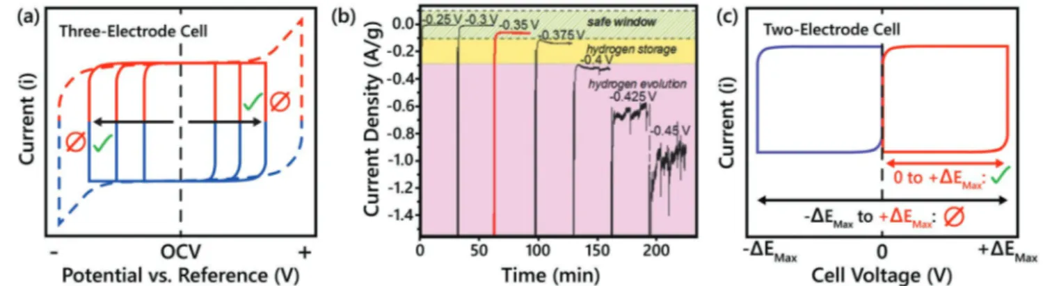
5. Determining the Operating Potential Window
Using Three- and Two-Electrode Cells
The operating potential window is a key parameter for cal-culating the energy density of an energy storage device and an improperly chosen potential window will have several defining characteristics. An EDLC with a properly chosen potential window will have a rectangular-shaped CV (solid line in Figure 4a), with a coulombic efficiency > 99%. Conversely, voltammograms showing exponential increases in their cur-rent response at high polarization (dashed line in Figure 4a), indicate that the device is being overcharged, resulting in the occurrence of parasitic side reactions, such as decomposition of the electrode material, the electrolyte, or a combination of both. The GCD curves of an overcharged supercapacitor also have easily recognizable features and will be similar in appearance to Figure 3. Schematic demonstration of practical differences existing for supercapacitors and batteries in GCD a) nonlinear supercapacitor GCD curves, b) GCD curves with charge (red) and discharge (blue) plateaus at different potentials.
Figure 3a. In most cases, supercapacitors with incorrect poten-tial windows will have coulombic efficiencies lower than 99%.
When determining the safe operating potential window of an electrode, there are two standard methods: i) incrementally increasing the potential window and evaluating the coulombic efficiency of the resulting CVs, and ii) by using chronoamper-ometry to perform successive potential-hold tests.[15] If using
cyclic voltammetry, capacitive-type electrodes (at typical mass loadings of >1 mg cm−2) under investigation must be cycled
at a low scan rate (2–5 mV s−1) while increasing the operating potential window in ≈0.2 V increments and calculating the resulting coulombic efficiencies (Figure 4a).[16] For
superca-pacitor systems evaluated using this method, the cut off limit is when the coulombic efficiency drops below 99%. For further evaluation of the stability of the chosen potential window, the use of chronoamperometry is the next recommended tech-nique. During chronoamperometry, constant potentials are applied to a single electrode with a large instantaneous current response being recorded. The intensity of this current response will decrease over time until it finally stabilizes. Figure 4b shows chronoamperometry results for a Ti3C2 MXene
elec-trode in 1 m H2SO4 electrolyte for various potential windows.
The final current density (A g−1), or leakage current, should be
close to zero if no parasitic reactions are occurring.[15]
However, the methods mentioned above are only applicable to three-electrode cells, where only the potential and current responses of the working electrode are being monitored. For a two-electrode supercapacitor device, the cell voltage, that is the absolute value of the potential between the positive and nega-tive electrodes, is being recorded. The total cell voltage can be approximated from three-electrode tests for the materials used in each electrode, but the total cell voltage needs to be tested carefully and correctly. Figure 4c shows a simple CV for a two-electrode cell with a positive voltage window (0 to +ΔEMax). If we
assume the two electrodes of this device are symmetrical (i.e., both electrodes are equally capable of storing either cations or anions), then this cell will be perfectly capable of cycling from 0 to −ΔEMax. In this case the polarization of the cell will switch,
and the polarity of each electrode will be reversed. As a result, this hypothetical two-electrode cell can cycle from −ΔEMax to
+ΔEMax, leading to double the potential range. However,
oper-ating a cell in this manner has no practical meaning from a device performance point of view since crossing 0 V simply results in reversing the polarization of the cell, with no change in the amount of charge being stored or delivered.[17] From this
explanation it should be clear that it would be incorrect to use the voltage window depicted by the black arrow in Figure 4c when estimating the energy density of this two-electrode cell. By convention, two-electrode cells should only have a positive voltage window, where cycling starts from 0 V and goes to the maximum operating potential.
An important aspect of making two-electrode cells is bal-ancing the charge stored on the positive and negative electrodes to ensure the maximum operating potential window while pre-venting uneven degradation of the individual electrodes. This practice is most commonly seen and discussed in the fabrica-tion of asymmetric cells or hybrid cells, however, even sym-metric EDLC-type cells require balancing as the size of cations and anions can vary significantly and affect the charge stored at each electrode, even if the same type of activated carbon is being used.[18] Due to the context of this essay, we recommended that
anytime a full cell (two-electrode device) is being reported on that authors report how the balancing of charge for the individual electrodes was done. Typically, the absolute charge on each elec-trode will be used to balance the elecelec-trodes correctly, and if this is the case the authors should report the capacity of the elec-trodes (C g−1 or mAh g−1), even if the electrodes are EDLC
mate-rials. The supporting information or the characterization section of a manuscript are good places for this information.
6. Possible Misinterpretation of Impedance Data
Electrochemical impedance spectroscopy (EIS) is a powerful analytical technique in characterizing electrochemical cells in various frequency regimes. Unlike cyclic voltammetry and GCD tests which constantly disrupt the state of the electrochemical system due to their dynamic nature, EIS experiments are per-formed on systems that are in an equilibrated state. Typically, a small sinusoidal voltage (5 or 10 mV, but higher voltages are Figure 4. Proper determination of the operating windows of a three- or two-electrode system. a) Schematic of CVs in a three-electrode cell for a safe operating window (solid line) and a potential windows showing side parasitic reactions (dashed lines), b) Chronoamperometry of MXene material in aqueous electrolyte for successive applied potentials, where parasitic reactions are characterized by an unstable (absolute) current over time increasing quickly while the applied potential is increased, Reproduced with permission.[15] Copyright 2015, John Wiley and Sons. c) Schematic of CV curves of a
potentially needed if the total impedance of the cell is high) is superimposed on a DC potential input (or at the open circuit potential) to measure the impedance of the cell as a function of frequency (the typical frequency range is from 100 kHz down to 10 mHz).[19] There are two common ways of representing
impedance data: i) the Bode plot, which represents the phase angle (Φ) and the absolute impedance modulus (Z) as a func-tion of frequency, and ii) the more commonly seen Nyquist plot, which plots imaginary and real impedances at different frequencies. Impedance data are usually recorded and plotted starting from the high-frequency domain (≈100 kHz) to the low frequency domain (≈10 mHz), in which distinct behaviors can be analyzed for the different frequency regimes. Nyquist plots should be represented in absolute one-to-one ratio, where the X- and Y-axes form a square plot. The point intersecting the real axis (X-axis) of the impedance at the highest measured frequency in a Nyquist plot gives the equivalent series resist-ance (ESR) of the cell under study (Figure 5a). Subsequent semicircle(s), a 45° line region, and a 90° angle line region with respect to the real axis of impedance are typical signatures observed for the charge storage mechanisms of the capacitive and pseudocapacitive materials discussed in this text, and their associated interfacial phenomena. It is very easy to perform an EIS measurement, however, sometimes it is very tricky to interpret the recorded data due to instrumental and cell-based artifacts.[20]
The EIS of porous electrodes in electrolyte solutions has been investigated extensively and there are classic models, namely, the transmission line model, that thoroughly describe the impedance of these electrodes.[21] At the most simplistic
level, a supercapacitor can be modeled using a combination of resistive and capacitive elements. The main resistive ele-ment, the ESR, originates from the total internal resistance of the cell (an additive effect from the cell components and electrolytes). The ESR is a typical element responsible for the dissipation of stored energy, and the magnitude of the ESR limits the total power performance and energy efficiency of the electrochemical cell. True supercapacitors should never show a semicircle in the high-frequency region, as the porous
carbon electrodes store charges in a physical manner without any charge transfer. We instead should expect to see a 45° line starting immediately from the ESR, which is typical for porous electrodes, followed by a vertical line that is parallel – or close to parallel – to the imaginary impedance axis (Y-axis) in the lower frequency region (Figure 5a, green line). A short 45° line transitioning into a fast increase of the imaginary part of the impedance in the low-frequency region is described by Diard et al. as evidence that all the reactive sites are fully accessible in a short time, leading to capacitor-like behavior.[22] However,
many published papers report semicircles in the high-fre-quency regions of their Nyquist plots for typical EDLCs and pseudocapacitive materials and go on to erroneously claim contributions from charge transfer resistance (RCT, see blue
curve of Figure 5a for an exaggerated example). These semicir-cles could indeed be due to the presence of functional groups or dopants at the surface of the carbon materials contributing to charge transfer events, or from the faradaic reactions occur-ring in pseudocapacitive materials, but the most likely reason for observing semicircles in laboratory cells is interfacial impedance occurring at the current collector/active material interface.[23] As widespread as the misinterpretation of charge
transfer resistance is, it is important for researchers to validate whether any semicircle recorded in a Nyquist plot during an EIS experiment is due to interfacial contact resistance or due to charge transfer. It is simple enough to identify whether a recorded semicircle comes from charge transfer resistance or from interfacial impedance by recording impedance spectra at multiple potentials, where one will be able to observe that a true RCT changes with potential (Figure 5b). This is unlike
interfacial impedance which will be constant across all potentials tested and the only notable changes in the imped-ance spectra will be in the low-frequency region (Figure 5c), where a shift of the imaginary part of the impedance from the theoretical 90° line can be observed, due to the porous elec-trode structure.
Often, passive coatings on current collector materials limits ohmic coupling between the current collectors and the electrode material, which is the main cause for semicircles Figure 5. a) Typical Nyquist plot representations for an EDLC (green curve), pseudocapacitive materials (blue) and battery (red). ESR, 45° and 90° lines are marked, b) Example spectra of confirming real charge transfer resistance (RCT) by doing EIS at two different potentials (solid and dotted
blue curves), in contrast to c) where interfacial impedance would lead to constant RCT at all potentials. Pseudocapacitive materials will show minimal
appearing in the high-frequency region of EDLCs. Interfacial impedance from passivation layers can be minimized through roughening of current collectors, by using coatings that inter-face with active materials better than the bare metals, and by using proper crimping parameters. The native alumina layer on commonly used aluminum foil current collectors can give rise to noticeable semicircles, which can be mitigated by treating the Al-foil to remove the passive coating.[23] Processing of
cur-rent collector surfaces is largely ignored, but this step can be critical and should be done to eliminate such effects for the design of efficient electrochemical devices.
Direct growth of electrode materials onto current collectors is the best strategy to ensure intimate contact between the two and no semicircles will be observed in the high-frequency region.[24]
In most cases however, it will not be viable or practical to grow electrode materials directly onto current collectors. In this sce-nario, either free-standing electrodes or conventional slurry casting methods need to be employed for testing the active mate-rials in electrodes and cells. In such cases, the pressure used when assembling either Swagelok-style or coin cell systems will significantly influence the high-frequency impedance of the cell.
Charge transfer rate (τ = 1/2πfm) can be estimated from
the peak frequency (fm) of the semicircle, which may be used as a characteristic time scale for differentiating between fast surface redox charge storage (pseudocapacitive) versus bulk intercalation (battery-like). One should use appropriate equiva-lent circuit models when fitting impedance data for extracting associated resistive, charge transfer, diffusive, and capacitive parameters for a given electrochemical cell.
When attempting quantitative impedance analysis of three-electrode cells, care must be taken in terms of the working condition of the reference electrode and passive coatings on the working electrodes. The porous frits used in reference elec-trodes may have high impedance for ion flow, which additively will contribute to a large impedance for the three-electrode cell as the applied potential is very small (≈5–10 mV, equilibrium state). Clogged reference electrode junctions and air bubbles in the filling solution of the reference electrode as well as the distance between the reference and the working electrodes can contribute significantly t o t he i mpedance o f t he c ell. To m ini-mize errors associated with reference electrodes, it is impor-tant not only to choose the right electrodes, but also maintain them properly. Attention should also be paid to the state of charge of the working electrode for accurate impedance anal-ysis. It is generally recommended that quantitative analysis of three-electrode cells be avoided for the previously discussed reasons. However, if quantitative analysis is necessary, we cau-tion researchers to first eliminate all possible sources of cell- or instrument-based artifacts that may influence t he i mpedance of their electrochemical systems. For most studies conducted using three-electrode cells qualitative discussions regarding the frequency response of the working electrode are appropriate.
7.
Ragone Plots: Energy and Power Densities
of Two-Electrode Devices
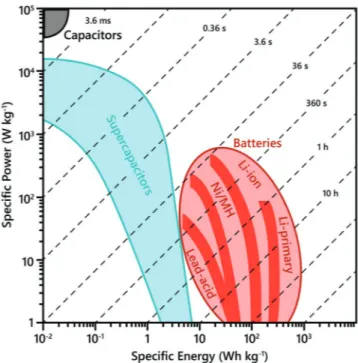
One of the most common ways in which the performance of elec-trochemical energy storage devices is represented and compared
is through Ragone plots (Figure 6), which intuitively demon-strate the relationship between a device’s energy and power densities and how that device matches up against comparable, competing systems. Ragone plots are also useful in showing how the performance of current technologies stack-up against the target performance region that developmental electrochem-ical systems are trying to achieve.
However, as was the case in previous sections, Ragone plots tend to be misimplemented, and overinflation of reported values that do not necessarily translate into device perfor-mance is commonplace. In most cases this is simply the result of erroneously calculating or extrapolating energy densities. However, erroneous comparisons of material-based perfor-mance values with the perforperfor-mance of commercial devices are not uncommon, where authors will not take into account that data reported for commercial devices uses the total volume and weight of the packaged device when reporting normalized energy and power densities. For commercial supercapacitors, the activated carbon used as the active material only accounts for approximately 1/3 of the total device weight. For this reason, material-based values should be reduced by factor of 3–4 when researchers attempt to make a realistic estimate of device-level values. However, it should be noted that this does not consider the differences commercial and laboratory electrodes have in terms of mass loading, density, and thickness. Laboratory scale electrodes are often ten times thinner/lighter than com-mercial electrodes, a factor that when lab electrodes are scaled up to commercial standards will lead to another reduction by three or four times to the laboratory electrode’s energy density. Data obtained on thin films supported on Ni or carbon foam should never be used in Ragone plots due to how far removed from any sort of realistic cell design or electrode architecture
Figure 6. Ragone plot showing the energy and power relationships of current electrochemical energy storage technologies with their associated time constant regimes.
these types of electrodes are. Comparisons of electrochemical performance are often central points in the publications for both battery and supercapacitor electrode materials, however, the performance of any electrode material is heavily dependent on the mass loading. Though our community has not agreed on specific requirements for mass loading, or areal capacity loading, this is an important consideration as studies on lab-scale electrodes (sometimes with mass loadings of only tens of µg cm−2) may greatly overestimate their own performance.
It is necessary to report not only the mass loading, but also how the material’s performance depends on the mass loading of the electrode. Editors and reviewers should be critical about some “outstanding” results in literature obtained at an extremely low mass loading (<1 mg cm−2).
This has been discussed thoroughly in the literature[25] and
we encourage readers to consider these previous reports in full. All results presented in Ragone plots must be taken with cau-tion and be looked at with the context in which they are being reported/calculated. It is acceptable to compare performance using a Ragone plot, as long as authors clarify whether it is a material-level or a device-level comparison being made (based on the weight of electrode materials or the whole device). Com-parisons of material-level performance from one study with the device-level performance of another study should never be done.
With these factors in mind, we believe it is important to introduce the idea of including a form factor when comparing energy and power density values to commercial systems. This form factor should include the size, dimensions, and composi-tion of the device being tested. Stack cell elements such as the current collectors, separator, electrolyte, and active materials should be included in the normalization of reported power and energy, so that performance per stack cell unit (weight or volume) can be plotted. In many cases though, including a form factor correction may be impractical for a laboratory scale cell, and since Ragone plots are exceptionally useful tools for reporting electrochemical data, we feel there are two cases where reporting energy and power densities based on the active material weight, or volume, alone are appropriate: i) when comparing a set of similar electrode materials within a single study, or ii) when comparing an electrode material to reports in the literature that have materials with similar packing den-sities, mass loading, and testing conditions (such as current density or scanning rate). By proceeding in this manner, we can make accurate judgments on the merits of new materials and stem the spread of misleading information. In all cases, the Ragone plot must be accompanied with a table referring to the relevant parameters mentioned above (form factors, testing conditions, etc.) for the studied device and for any performance taken from literature that is being used for comparison. Also, Ragone plots are useful snapshots of the energy and power performance of a set of devices, but they are not sufficient for full comparison of the performance of devices. Other metrics, such as device lifetime, cycling stability, self-discharge, and coulombic and energy efficiencies are required, as described in previous sections.
In cases where researchers do wish to accurately compare the performance of their materials to industrial devices, the fairest comparison that can be made is through evaluation of
the response times of the materials and devices in question. The ratio between the energy density and power density gives the response time of the device. This response time is char-acteristic of the nature of the device, where there are distinct regions for capacitor-like or battery-like systems on Ragone plots, as represented by the diagonal dashed lines in Figure 6. There are many cases where “supercapacitor” systems claim exceptional energy densities at the expense of their power per-formance. If the time constants of these systems were to be calculated it would be apparent that they have actually moved into the response time region of batteries, making these sys-tems just sub-par batteries. Calculation of the response time for any system will give a clear and fair evaluation of the con-text in which its performance should be judged. The response time τ is a universal parameter for comparing various classes of energy storage devices irrespective of any form factor discrep-ancies between laboratory-scaled devices or packaged devices, or of any discrepancies in the normalization used (weight, length, area, or volume).
In all cases, it is necessary to use the proper calcula-tion methods when evaluating energy and power, and sub-sequently the time constant, of any energy storage system. Thorough derivations of the proper equations to use for both batteries and supercapacitors have been described in many books and literature reviews,[25,26] which we recommend
readers review for detailed understanding. Here we will only list the common equations used for supercapacitor systems and emphasis that the proper requirements should be met to classify the system as “capacitive” (analogous to Sections 1, 2, 3), otherwise gross over-estimations of the systems energy will occur, as was demonstrated in Figure 2 for the improper calculation of capacitance for a battery-type material. The most common equations for energy and power normalized with respect to weight, area, and volume of the devices are listed below
Gravimetric energy density, g 1 0 d
d E M iV t t
∫
= (8)where M is the total mass of the device, i is the discharge cur-rent, V is the potential, and td is the discharge time. Calculating
the charge delivered via integration will eliminate any uncer-tainty due to nonlinearities in the device’s discharge profile
Average gravimetric power density, g g d
P E
t
= (9)
The areal and volumetric energy and power densities are obtained by multiplying the total mass loading (g cm−2) and total material density (g cm−3) by the gravimetric energy/power
den-sity, respectively. An important note to consider for when the device is asymmetric, which is becoming more and more pop-ular in the literature, the material density and mass loading are usually different for the positive and negative electrodes. In this case, the calculation of the volumetric energy density should use the average material density expressed as: ρ = total mass /total volume.
The use of the proper calculation methods, fair assessments of time constants, and the inclusion of form factors will ensure
proper evaluation of the energy and power performance of new materials and electrode architectures.
8. A New Generation of Energy Storage Devices:
Fiber- and Micro-Supercapacitors
The latest advancements in miniaturized electronics and textile-based electronics have seen increased demand for developing compatible power sources with the goal of inte-grated solutions for autonomous smart devices. For example, micro-supercapacitors and fiber-supercapacitors are being researched extensively as micropower sources for on-chip and textile-based electronics, respectively.[27] There is always
a trade-off between electrochemical performance when downscaling of active electrode materials, and these types of miniaturized supercapacitors use negligible amounts of active materials (typical mass loadings of <0.1 mg cm−2) and their
electrical output responses may deviate significantly from standard laboratory test cells, such as Swageloks, coin cells, and pouch cells. In the case of micro- and fiber-supercapac-itors, performance metrics should be normalized based on the length, area, and volume of the device for accurate esti-mations unlike the overestiesti-mations made when gravimetric performance is reported, which is usually irrelevant for these applications.
Electrode materials are sometimes formulated in the form of printable inks for micro-supercapacitor fabrication. Non-conductive additives in the inks and active materials with intrinsically low electrical conductivity make devices com-posed of such materials highly likely to show nonideal cycling behavior during cyclic voltammetry, and their charge–dis-charge cycles tend to resemble those shown in Figure 7. Recently, Boonpakdee et al. introduced a simple yet compre-hensive methodology to tackle such imperfections by using equivalent circuit analysis.[28] Building physical equivalent
circuits composed of capacitive and resistive elements can be used to simulate the distorted CV profiles seen in some experi-mental devices. The fitting parameters can then be adjusted to account for the recorded CV shapes while extracting circuit parameters. Boonpakdee et al. were able to extract parameters from their circuit analysis with a 95% accuracy rate. A sche-matic version of this idea is shown in Figure 7, where equiva-lent circuit models can be made based off the shape of CVs for analysis of the charge being stored. We recommend readers to refer to the report of Boonpakdee et al. for the technical details of this process.[28] Adoption of this kind of analysis helps in the
selection of the right operational voltage window by avoiding parasitic faradaic reactions at higher cut-off voltages for the device. Furthermore, resistive voltammograms should not be considered when trying to estimate capacitance values, as this behavior is predominantly due to a resistive component rather than one of a capacitive nature. In these cases, proper engi-neering of devices should be done to account for minimizing resistive losses. We encourage researchers working on micro-supercapacitors and fiber-based micro-supercapacitors to estimate accurate performance metrics by taking the above analysis into consideration.
9. Outlook and Perspectives
We hope we have effectively emphasized the need for the elec-trochemical energy storage field to be united in its stance on material characterization and reporting appropriate electro-chemical performance metrics. This discussion is by no means exhaustive, but is meant to encourage researchers, reviewers, and editors to consider and further educate themselves on the fundamentals and correct methods of data reporting in this field. To this end, we would like to point toward a few references[6,8,17,19,25] that we believe will be instructive for
anyone seeking deeper understanding of some of the different topics discussed in this text. We have also included a short checklist of some the typical questions we keep in mind when we are reviewing the merit of any study into the electrochemical properties of a material or a device. Our hope is to help guide future energy researchers along a path that is based on reliable research, not one that is mired with inconsistent reports and standards.
Supporting Information
Supporting Information is available from the Wiley Online Library or from the author.
Acknowledgements
The researchers involved in preparing this article were supported by the Fluid Interface Reactions, Structures & Transport Center, an Energy Figure 7. Equivalent circuit analysis for different cyclic voltammetry pro-files. a) ideal CV profile. b) slanted, c) blunt, and d) mix of blunt and slanted CV profiles and their corresponding equivalent circuit models are shown in the insets, where C is a capacitive element and RP and Rs are
Frontier Research Center funded by the US Department of Energy, Office of Science, Office of Basic Energy Sciences.
Conflict of Interest
The authors declare no conflict of interest.
Keywords
best practices, capacitance, energy storage, nanomaterials, protocols, pseudocapacitance, reporting methods
Received: June 21, 2019 Revised: August 7, 2019 Published online: September 4, 2019
[1] Y. Gogotsi, ACS Nano 2014, 8, 5369.
[2] Y. Gogotsi, R. M. Penner, ACS Nano 2018, 12, 2081.
[3] S. Ardizzone, G. Fregonara, S. Trasatti, Electrochim. Acta 1990, 35, 263. [4] a) H. Lindström, S. Södergren, A. Solbrand, H. Rensmo, J. Hjelm, A. Hagfeldt, S.-E. Lindquist, J. Phys. Chem. B 1997, 101, 7710; b) J. Wang, J. Polleux, J. Lim, B. Dunn, J. Phys. Chem. C 2007, 111, 14925.
[5] A. J. Bard, L. R. Faulkner, Electrochemical Methods: Fundamentals
and Applications, J. Wiley, New York, Toronto 2001.
[6] P. Simon, Y. Gogotsi, B. Dunn, Science 2014, 343, 1210.
[7] A. J. Bard, L. R. Faulkner, Electrochemical Methods: Fundamentals and
Applications, John Wiley & Sons, New York 1980.
[8] T. Brousse, D. Bélanger, J. W. Long, J. Electrochem. Soc. 2015, 162, A5185.
[9] M. R. Lukatskaya, B. Dunn, Y. Gogotsi, Nat. Commun. 2016, 7, 12647.
[10] J. S. Ko, M. B. Sassin, D. R. Rolison, J. W. Long, Electrochim. Acta 2018, 275, 225.
[11] M. Forghani, S. W. Donne, J. Electrochem. Soc. 2018, 165, A664. [12] H. Shao, Z. Lin, K. Xu, P.-L. Taberna, P. Simon, Energy Storage
Mater. 2019, 18, 456.
[13] X. Yang, A. L. Rogach, Adv. Energy Mater. 2019, 9, 1900747. [14] a) F. Béguin, V. Presser, A. Balducci, E. Frackowiak, Adv. Mater.
2014, 26, 2219; b) A. Balducci, D. Belanger, T. Brousse, J. W. Long, W. Sugimoto, J. Electrochem. Soc. 2017, 164, A1487.
[15] M. R. Lukatskaya, S.-M. Bak, X. Yu, X.-Q. Yang, M. W. Barsoum, Y. Gogotsi, Adv. Energy Mater. 2015, 5, 1500589.
[16] C. Schütter, T. Husch, M. Korth, A. Balducci, J. Phys. Chem. C 2015,
119, 13413.
[17] M. D. Stoller, R. S. Ruoff, Energy Environ. Sci. 2010, 3, 1294. [18] K. L. Van Aken, M. Beidaghi, Y. Gogotsi, Angew. Chem., Int. Ed.
2015, 54, 4806.
[19] P. L. Taberna, P. Simon, J. F. FauvarqueJ. Electrochem. Soc. 2003,
150, A292.
[20] M. D. Levi, V. Dargel, Y. Shilina, D. Aurbach, I. C. Halalay,
Electrochim. Acta 2014, 149, 126.
[21] R. de Levie, Electrochim. Acta 1963, 8, 751.
[22] J. P. Diard, B. Le Gorrec, C. Montella, J. Electroanal. Chem. 1999,
471, 126.
[23] C. Portet, P. L. Taberna, P. Simon, C. Laberty-Robert, Electrochim.
Acta 2004, 49, 905.
[24] J. R. Miller, R. A. Outlaw, B. C. Holloway, Science 2010, 329, 1637.
[25] S. Zhang, N. Pan, Adv. Energy Mater. 2015, 5, 1401401.
[26] a) A. Laheäär, P. Przygocki, Q. Abbas, F. Béguin, Electrochem.
Commun. 2015, 60, 21; b) J. Xie, P. Yang, Y. Wang, T. Qi, Y. Lei,
C. M. Li, J. Power Sources 2018, 401, 213.
[27] a) M. Beidaghi, Y. Gogotsi, Energy Environ. Sci. 2014, 7, 867; b) K. Jost, G. Dion, Y. Gogotsi, J. Mater. Chem. A 2014, 2, 10776.
[28] D. Boonpakdee, C. F. Guajardo Yévenes, W. Surareungchai, C. La-o-vorakiat, J. Mater. Chem. A 2018, 6, 7162.