OATAO is an open access repository that collects the work of Toulouse
researchers and makes it freely available over the web where possible
Any correspondence concerning this service should be sent
to the repository administrator:
[email protected]
This is an author’s version published in:
http://oatao.univ-toulouse.fr/24219
To cite this version:
Chong, Poehere
and Erable, Benjamin
and Bergel, Alain
Effect of pore
size on the current produced by 3-dimensional porous microbial anodes: A
critical review. (2019) Bioresource Technology, 289. 121641. ISSN 0960-8524
Effect of pore size on the current produced by 3-dimensional porous
microbial
anodes: A critical review
Poehere
Chong, Benjamin Erable, Alain Bergel
⁎ Laboratoire de Génie Chimique, Université de Toulouse, CNRS, INP, UPS, Toulouse, FranceG R A P H I C A L A B S T R A C T A R T I C L E I N F O Keywords: Bioanode Porosity Electroactive biofilm Microbial fuel cell Bioelectrochemical system
A B S T R A C T
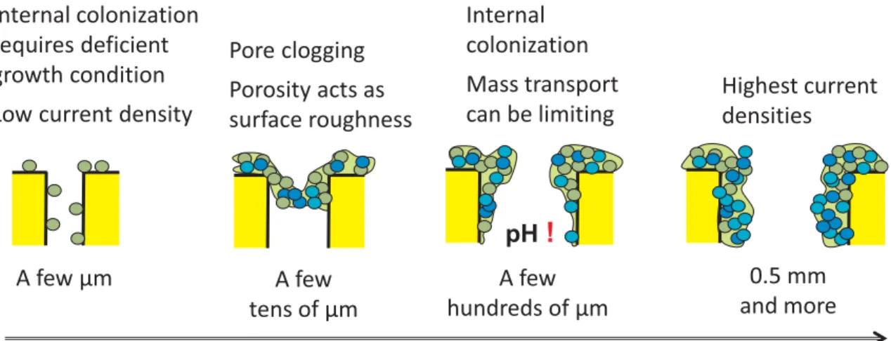
Microbial anodes are the cornerstone of most electro-microbial processes. Designing 3-dimensional porous electrodes to increase the surface area of the electroactive biofilm they support is a key challenge in order to boost their performance. In this context, the critical review presented here aims to assess whether an optimal range of pore size may exist for the design of microbial anodes. Pore sizes of a few micrometres can enable microbial cells to penetrate but in conditions that do not favour efficient development of electroactive biofilms. Pores of a few tens of micrometres are subject to clogging. Sizes of a few hundreds of micrometres allow pe-netration of the biofilm inside the structure, but its development is limited by internal acidification. Consequently, pore sizes of a millimetre or so appear to be the most suitable. In addition, a simple theoretical approach is described to establish basis for porous microbial anode design.
1. Introduction
The capacity of microbial biofilms to catalyse electrochemical re-actions has led researchers to rethink all electrochemical processes (Wang and Ren, 2013; Schröder et al., 2015; Bajracharya et al., 2016). Introducing microbial electrocatalysis in fuel cells, electrolysis cells, electrosynthesis cells, electrodialysis cells, sensors, and all kinds of processes that involve electrochemistry, has encouraged the emergence of an extraordinary variety of new technologies. Although some
optimistic prospects initially put forward should now be qualified, there can be no doubt that this conceptual blossoming will lead to practical applications, such as powering remote sensors (Dewan et al., 2014) and designing autonomous sensors (Di Lorenzo et al., 2009; Pasternak et al., 2017). Completely new technologies, based on simple galvanic cou-pling of anode and cathode, also seem promising, e.g. the electro-chemical snorkel (Erable et al., 2011; Cruz Viggi et al., 2015) and the catalysis of direct interspecies electron transfer through conductive particles (Kato et al., 2011, 2012; Liu et al., 2012).
⁎
Corresponding author at: Laboratoire de Génie Chimique, BP 84234, 4 allée Emile Monso, 31432 Toulouse, France. E-mail address:[email protected](A. Bergel).
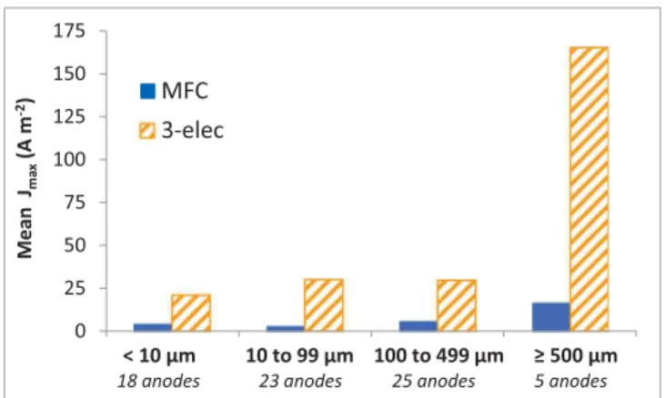
available surface area and the pore size depends on the porosity (i.e. void fraction). Nevertheless, the pore size is generally decreased in the aim of increasing the available surface area. With this rule of thumb in mind, the evolution of Jmaxobserved here, in the opposite sense to the
available surface area, is intriguing and deserves deeper analysis. The results have also been distinguished inFig. 1depending on the type of experimental set-up used to record the data. In most cases, controlled polarization performed with a 3-electrode set-up led to higher maximum current density than microbial fuel cells (MFCs). As already commented in detail elsewhere (Rimboud et al., 2014), using microbial fuel cells (MFCs) may often lead to the performance of mi-crobial anodes being underestimated, mainly because of the numerous rate-limiting steps that can be involved in an MFC. Furthermore, an MFC often does not allow the anode to be polarized at potential values high enough to reach the highest possible currents. Three-electrode set-ups should consequently be preferred to MFC when the objective is to characterize electrodes.
Each section is commented below using the usual distinction be-tween monolithic and fibre porous electrodes (Xie et al., 2015; Yu et al., 2017), which correspond to markedly different architectures. Mono-lithic electrodes are manufactured from a continuous block, initially made with pores or which has been perforated to create pores. This group gathers together porous electrodes in the form of foams and sponges e.g., made from aerogels and natural, organic and inorganic, porous templates, often by carbonization. Fibre porous electrodes are composed of interwoven threads such as mesh, cloth, felt or carbon paper. For fibre electrodes, when no indication about an equivalent pore size was given in the article, the mean spacing between fibres of the network was considered as the pore size .
3. Pore size below 10 µm (Table 1)
3.1. Impact of the pore size on microbial colonization 3.1.1. Monolithic porous structures
The size of bacterial cells generally ranges between 0.5 and 3 µm, and is most often around 1–2 µm (Jiang et al., 2014). Internal coloni-zation of porous structures has consequently never been reported with pore diameters smaller than 1 µm. It would be very difficult for mi-croorganisms to penetrate into such narrow pores, except under specific conditions, for instance, if pressure was imposed through the porous material (Gaveau et al., 2017). With pore sizes around 1 µm and less, the main advantage of the 3D porous electrodes would be lost because biofilm would grow only on the outer surface. Nevertheless, it cannot be ruled out that such small pore sizes may promote cell anchoring and biofilm development by creating surface roughness (Champigneux et al., 2018a).
Fig. 1. Mean values of maximum current density as a function for four ranges of pore sizes. The data obtained with microbial fuel cells (MFC) are distinguished from those obtained under applied potential in 3-electrode set-ups (3-elec).
Regardless of the intended application, the objective is most often to increase the process rate, i.e. the current density expressed in relation to the electrode projected surface area. The first solution the engineer thinks of is to increase the surface area of the electroactive biofilm by using 3-dimensional (3D) porous electrodes. Electro-microbial pro-cesses have consequently made extensive use of 3D porous electrodes. The wide-reaching literature devoted to 3D porous electrodes has been reviewed from many different aspects, including the nature of the electrode materials (Wei et al., 2011; Zhou et al., 2011; Sonawane et al., 2017), surface modifications (Hindatu et al., 2017), and fabrication processes (Xie et al., 2015; Yu et al., 2017; Lai et al., 2018).
In spite of very helpful recent review articles, the engineer who intends to design a 3D porous microbial anode still faces a lack of in-formation about the optimal range of pore size that should be used, and he/she even have considerable difficulty in establishing whether an optimal range of pore sizes may exist. The purpose of the present article is to extract information from the literature to advance on this topic. 3D porous microbial anodes were analysed from two main aspects. Firstly, the main objective of using 3D porous electrodes is to increase the surface area available for the electroactive biofilm to develop. It is thus essential to question whether the different porous structures perform this function. In this context, this review focuses on the information available in the literature about microbial colonization of 3D porous anodes and particularly the penetration of microbial colonization into the structure. Secondly, whatever the contemplated application, the main technological objective is to maximise the current density pro-duced. The microbial anodes were consequently compared on the basis of the maximum current density they provided (Jmax, A m−2), which
was always calculated with respect to the anode projected surface area in order to obtain comparable values.
Whenever possible, a relationship was sought between current density and the microbial colonization situation. Combining these two lines of analysis revealed unanticipated trends and led to non-current advice on how to progress in optimizing 3D porous structures to form microbial anodes. We thus hope to influence the future research di-rections of the many groups involved in the optimization of microbial anodes in order to save them time in progressing towards optimal porous structures.
2. General remarks and organisation of the review
The electrodes were analysed by defining four groups according to the pore sizes: pores of less than 10 µm, from 10 to 99 µm, from 100 to 499 µm, and from 500 µm upwards. It was possible to analyse 71 dif-ferent microbial anodes (the number of electrodes is indicated rather than the number of articles because one article can describe several types of electrodes). Actually, many other examples of 3D porous electrodes have been reported in the literature but it was not always possible to find a reliable value of the mean pore size. In particular, beds of granules have often been implemented to form microbial an-odes (Aelterman et al., 2008; Rabaey et al., 2005a,b; Wang et al., 2011) but they were not included in the present analysis, although they constitute 3D porous structures, because they generally have a wide range of pore sizes, which are very difficult to characterize through a single mean value.
A first rough approach to the topic consisted in plotting the max-imum current density reported for each electrode according to the four pore size groups defined above (Fig. 1). The graph revealed an un-anticipated impact of the pore size on the current output, with a great enhancement at pore sizes of at least 500 µm. This simple graph gave an answer about the possible existence of an optimal pore size for micro-bial anodes: an optimal pore size range does indeed exist and it is of the order of millimetre(s).
This trend was counter-intuitive because it could be expected that the available surface area would increase when the pore size decreases. This relationship is not always valid because the link between the
Several studies have reported that pores with sizes ranging from 2 to 10 µm display internal colonization by microbial cells. Porous elec-trodes manufactured by carbonizing corn stem, with pores ranging from 2 to 7 µm in diameter, showed bacterial communities present on both the external and internal surfaces (Karthikeyan et al., 2015). In this case the microbial anodes were prepared from a multi-species microbial consortium coming from a sewage station. Biofilm thickness inside the pores was strongly dependent on the pore diameter whereas, on the external surface, a thicker biofilm of approximately 3–18 µm had formed after 18 days.
Similarly, different microbial anodes prepared from microcellular polyacrylonitrile (PAN), with mean diameters of around 5 µm or 2.5 µm, showed internal colonization by Escherichia coli (Wang et al., 2015a). Graphene aerogel (GA) has led to a similar range of porosity (Xu et al., 2010) (Yin et al., 2013). GA has been implemented directly (Zhao et al., 2015), with Pt nanoparticles scattered on its surface (GA/ Pt) (Zhao et al., 2015), or doped with nitrogen (GA/N) (Yang et al., 2016b). All these GA electrodes exhibited pore sizes ranging between 2 and 10 µm and supported well-developed biofilms of Shewanella onei-densis on their entire surfaces, including inside pores.
According to the studies commented above, pore sizes from 2 to 10 µm are large enough to allow the bacteria penetrate into the porous structure. Nevertheless, it might be feared that such small pores may be subject to clogging with time. Surprisingly, the studies that reported fairly long experiments, did not observe pore clogging after 18 days (Karthikeyan et al., 2015) and 25 days of experiment (Zhao et al., 2015; Yang et al., 2016b). Actually, the absence of pore clogging when the pore size is so close to the microbial cell size is quite intriguing.
The viability of bacteria was checked by epifluorescence microscopy inside the structure of GA/Pt microbial anodes after 25 days of opera-tion (Zhao et al., 2015). Almost all cells had remained alive. Only a few bacteria were dead, due to normal cell apoptosis. Nevertheless, the epifluorescence pictures showed very poor bacterial colonization, with mainly single adhered cells or small microbial colonies of a few cells scattered on the electrode surface. Such low colonization, even after 25 days of operation, explains the absence of pore clogging. It can be
suspected that no clogging was observed in these studies because the operating conditions did not allow a thick, uniform biofilm to develop. Most of these studies were performed with pure cultures (Table 1), which consequently avoided the anarchic development of thick bio-films, that is often the case with multi-species communities. The single study that implemented a multispecies inoculum (Karthikeyan et al., 2015) was carried out in a solution that contained only phosphate, so the nutrients, micro-nutrients and mineral components required for microbial growth came only from the inoculum. It is likely that such a poor medium limited the development of the biofilm, which may have been the main cause of the absence of clogging in spite of the small pore size.
To conclude on the colonization of monolithic porous electrodes with pore sizes below 10 µm, it can be noted that internal colonization is often due to specific operating conditions that limit biofilm growth. In studies where the internal colonization was characterized, only scattered colonies were observed.
3.1.2. Fibre porous structures
Carbon cloth is often used as the support for microbial anodes. Carbon cloth is made from fibres that are closely packed together so that the space between them is less than 10 µm. Whether they were implemented with pure or mixed cultures, all reports claimed that carbon cloths led to the formation of biofilms, which mainly covered the external surface of the electrode (Blanchet et al., 2016; Manickam et al., 2013;Yang et al., 2016b; Zhao et al., 2015). Colonization of the internal surface of the fibres has rarely been observed, but it must be acknowledged that looking at internal colonization is generally not a major purpose of the studies using carbon cloth. Furthermore, carbon cloth surface can be modified in order to improve microbial adhesion, by using additives, such as conductive polymers (polyaniline) (Hou et al., 2013; Lai et al., 2011) or nanomaterials (multi-walled carbon nanotubes) (Tsai et al., 2009), or by electrochemical treatment (Li et al., 2014; Liu et al., 2014; Zhang et al., 2014). Some of these surface modifications reduced the spacing between fibres or even totally filled the gap, so colonization of inner fibres did not occur (Hou et al., 2013;
Table 1
Three-dimensional porous microbial anodes with pore size less than 10 µm. 1C-MFC: single-compartment MFC ; 2C-MFC: two-compartment MFC ; 3-elect: polar-isation with a 3-electrode set-up vs. Ag/AgCl ; PAN: polyacrylonitrile; G: graphite ; GA: graphite aerogel ; PMBVF/PVA: poly (2-methacryloyloxyethyl phosphor-ylcholine-co-n-butyl methacrylate)-co-p-vinylphenylboronic acid-co-vinylferrocene/Poly (vinyl alcohol) ; PANI: polyaniline ; PEDOT: poly(3,4-ethylenediox-ythiophene) ; TSB: Tryptic soy broth.
Anode material Set-up Inoculum Substrate Pore size µm JmaxA m−2 Reference
Monolithic Carbon
Carbonized corn stem 1C-MFC sewage Acetate 100 mM 2–7 31.2 Karthikeyan et al., 2015
Carbonized PAN 1C-MFC E. coli Glucose 2 g L−1 5 2.03 Wang et al., 2015a
Carbonized PAN/graphite 1C-MFC E. coli Glucose 2 g L−1 2.5 2.91 Wang et al., 2015a
GA 2C-MFC S. oneidensis Lactate 18 mM 2–10 1.5 Zhao et al., 2015
GA/Pt 2C-MFC S. oneidensis Lactate 18 mM 2–10 2.4 Zhao et al., 2015
GA/N 2C-MFC S. oneidensis TSB 5–10 5.98 Yang et al., 2016b
Hybrid
PMBVF/PVA hydrogel 1C-MFC S. oneidensis Lactate 18 mM < 10 0.08 Lin et al., 2012
Fibre-based Carbon
Carbon cloth 2C-MFC S. oneidensis Lactate 18 mM < 10 0.4 Zhao et al., 2015
Carbon cloth 1C-MFC activated sludge Food wastes < 10 3.5 Blanchet et al., 2016
Carbon cloth 2C-MFC S. oneidensis Lactate 18 mM < 10 3.3 Yang et al., 2016a
Carbon cloth 1C-MFC wastewater Acetate < 10 5.3 Manickam et al., 2013
Activated carbon fibre 1C-MFC wastewater Acetate < 10 0.35 Manickam et al., 2013
Carbon fibre 3-elect 0.2 V wastewater Acetate 10 mM 6.8* 30.8 He et al., 2011
Carbon fibre 3-elect 0.2 V wastewater Acetate 10 mM 5.3* 29.9 He et al., 2011
Carbon fibre 3-elect 0.2 V wastewater Acetate 10 mM 1.6* 25.2 He et al., 2011
Carbon fibre 3-elect 0.2 V wastewater Acetate 10 mM 0.4* 17.4 He et al., 2011
Hybrid
BC/PANI 2C-MFC sludge Glucose 10 g L−1 < 2 0.617 Mashkour et al., 2016
PEDOT fibre 2C-MFC S. oneidensis TSB < 10 0.16 Jiang et al., 2015
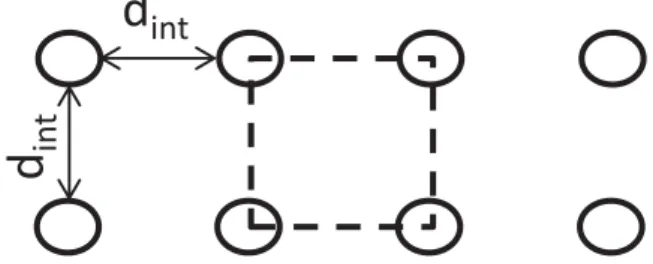
= − + χ πd d d 1 4 1 ( ) f f int 2 2 (1) where df(m) is the fibre diameter, and dint(m) is the inter-fibre
dis-tance. The ratio + d d
1
(f int)2 gives the number of fibres that are ordered perpendicularly to a surface area of 1 square meter. This ratio is also equal to the total length of the fibres contained in a volume of 1 cubic meter. According to this model, a carbon cloth made with fibres of 10 µm diameter 3 µm apart leads to a porosity of 54%, while a felt made of fibres of 1 µm diameter with the same inter-fibre spacing offers a porosity of 95%. This calculation clearly illustrates that, at identical inter-fibre distance, the electrodes manufactured with thinner fibres display a considerably larger porosity for letting microbial cells pene-trate into the structure. With similar inter-fibre distance, the space of-fered to the cells depends on the fibre diameter.
In this context, the inter-fibre distance, assimilated to an equivalent pore size, is no longer the only relevant parameter. If the purpose is to enhance the internal colonization of the electrode, the inter-fibre dis-tance must be large enough and, in addition, the electrode porosity must also be increased as much as possible.
The utility of such a simple model has been confirmed
experimentally byHe et al. (2011), who compared the impact of dif-ferent fibre diameters from 0.16 to 9.94 µm on the behaviour of biofilm formation in carbon fibre anodes (He et al., 2011). The fibre diameter (df), the porosity (χ), and the penetration depth of the biofilm inside the
structure were measured experimentally (Table 2). No obvious re-lationship could be established between the biofilm penetration depth and the porosity. For instance, the two lowest porosity values (93.5 and 95.2%) led to the smallest and the largest biofilm penetration depths (16.7 and 600 µm), respectively. Actually, the range of porosity values was too limited to be impacting in this case. The inter-fibre distance (dint) was assessed theoretically by using Eq. (1). This calculation
showed that the inter-fibre distance increased with the fibre diameter (Table 2). This gave an obvious explanation to the evolution of the biofilm penetration depth: the biofilm penetration depth increased with the inter-fibre distance. Moreover, the biofilm morphology changed, from continuous biofilms at small dintto porous biofilms at large dint, the
toggle value being between 6.8 and 12.6 µm. This example confirmed the essential importance of the porosity and inter-fibre distance para-meters when the objective is to understand the colonization of a fibre-based electrode.
The study byHe et al. (2011)also showed that the biofilm pene-tration remained weak for inter-fibre distances less than 10 µm. Pene-tration depths did not exceed 226 µm, which remains drastically limited if the objective is to design 3D porous microbial anodes. Only a very thin layer of the porous structure would be exploited by the biofilm. Actually, a uniform biofilm of around 200-µm thickness, filling the upper layer of a porous electrode, may be considered as clogging that prevents the porous structure from being fully exploited. It was neces-sary to increase the inter-fibre spacing above 10 µm to obtain a porous biofilm that did not clog the open structure of the electrodes (Table 2). 3.2. Electrochemical performance
A large majority of the microbial anodes with pore sizes less than 10 µm delivered weak maximum current densities, less than 5 A m−2
(Fig. 3). As remarked above, many studies were performed with pure cultures (Table 1) and in conditions that would favour the penetration of single cells into the structure rather than the formation of thick biofilms. Conditions optimized to favour internal colonization of narrow pores seem consequently detrimental to the development of efficient electroactive biofilms.
Only a few anodes gave current higher than 10 A m−2 (Fig. 3,
Table 1) Actually, these anodes came from only two studies. On the one hand, a monolithic porous anode, with pores of 2–7 µm, delivered current density of 31.2 A m−2
(Karthikeyan et al., 2015). On the other hand, the nano-fibre anodes designed by He et al. produced up to 30.8 A m−2 with pore size assessed as 6.8 µm (Table 2). These two
exceptions deserve deeper analysis.
Both studies used a microbial consortium, one coming from a sewage station (Karthikeyan et al., 2015) the other from a wastewater treatment plant (He et al., 2011), instead of pure cultures as in most other reports. Furthermore, the inoculum was implemented in a syn-thetic medium. In one case, the solution was only phosphate buffer, so the components required for microbial growth were only provided by the inoculum (Karthikeyan et al., 2015). In the other case, a synthetic medium was used and regularly refreshed. In addition, a prior selection of electroactive microorganisms was performed by forming a primary microbial anode that was then used as the inoculum to prepare the porous fibre-based microbial anodes (He et al., 2011). In both cases, the well-chosen operating conditions probably prevented the development of non-electroactive bacteria. Furthermore,Karthikeyan et al. (2015) used an unusually high substrate concentration, of 100 mM acetate, which probably mitigated transport limitation inside the porous struc-ture.
The fibre anodes designed byHe et al. (2011)also pointed out the importance of a third parameter if the objective is to increase the
Fig. 2. Scheme of the simplified arrangement of fibres used to establish the model; the dashed square represents an elementary area used for calculation.
Lai et al., 2011; Tsai et al., 2009; Liu et al., 2014; Li et al., 2014; Zhang et al., 2014).
Another way to manufacture porous electrodes from fibres is to pack them in disorder so as to form felts. Nanofibres have been used in this manner in order to increase the surface area available for cell adhesion while achieving high porosity (Pham et al., 2006; Smith and Ma, 2004; Manickam et al., 2013). Such a nano-fibre anode has been compared with carbon cloth having a similar inter-fibre distance of less than 10 µm. Both electrodes were inoculated with wastewater and fed with acetate (Manickam et al., 2013). Internal biofilm colonization was ob-served only in the felt nano-fibre anode. Similarly, a microbial anode made with conductive poly(3,4-ethylenedioxythiophene) (PEDOT) na-nofibres, with a mean pore size of several micrometres, inoculated with Shewanella oneidensis MR-1 and fed with lactate, showed full bacterial colonization of the internal nano-fibre structure (Jiang et al., 2015).
Apparently, nonwoven nanofibre-based anodes with inter-fibre spacing of less than 10 µm offer a suitable structure for internal colo-nization. In contrast, carbon cloth electrodes with similar inter-fibre spacing generally did not lead to the presence of bacteria in between the fibres.
Actually, we think that the difference is not related to the type of structure, nonwoven felt vs. woven cloth, but to the difference in the geometric pattern. The fibres used to weave carbon cloths typically have diameters around 10 µm, while felt structures are most often manufactured with much thinner fibres, including nano-fibres. The patterns offered to microbial colonization by these cloths and felts are consequently very different because of the difference in the fibre dia-meters.
A simple model can make this difference easier to grasp. For the sake of simplicity, let us consider layers of parallel fibres disposed as schematized in Fig. 2. This representation allows the electrode porosity, also called void fraction (χ), to be calculated easily as:
current density. With similar porosities of 97.2 and 97.9% (Table 2) the anodes with the higher inter-fibre distance (31.0 vs 1.6 µm) logically displayed considerably higher biofilm penetration depth (385 vs 24 µm) but they produced lower current density (1.65 vs 2.52 mA cm2). These
results illustrate the major importance of the volume of the electro-active biofilm. In this case, it was not measured but the surface area that was available to microbial colonization can be assessed theoreti-cally. Based on the simple representation evoked above (Fig. 2), the fibre surface area available per volume unit (As, m2m−3) is:
= + As πd d d 1 ( ) f f int2 (2)
This calculation shows that the 20 times smaller surface area (689 vs 13857 cm2cm3) provided by the anodes with the higher inter-fibre distance was probably responsible for a smaller amount of biofilm and consequently a lower current density (Table 2).
To conclude, when the objective is to design efficient porous mi-crobial electrodes, three main parameters must be considered. Porosity and pore size, which can be the inter-fibre distance for fibre electrodes, must be increased to promote the biofilm penetration inside the structure. Conversely, the specific surface area must be increased to increase the surface area for biofilm development. Increasing these three parameters concomitantly is not possible, so an optimum must be sought. These three parameters provide simple tools to advance to-wards the optimization of microbial 3D porous electrodes .
4. Pore size from 10 to 99 µm (Table 3) 4.1. Impact of the pore size on microbial colonization 4.1.1. Monolithic porous structures
Pore sizes of a few tens of micrometres are, a priori, large enough to allow microorganisms to penetrate inside the pores easily and to ensure significant mass transport inside the internal structure (Yong et al., 2014; Huang et al., 2016). All the studies that have examined the in-ternal colonization of such porous electrodes state that microbial bio-film formed on both the external and internal surfaces (Baudler et al., 2017; Chen et al., 2012a; Han et al., 2016; He et al., 2012; Karthikeyan et al., 2015; Katuri et al., 2011; Massazza et al., 2015; Yong et al., 2014).
However, as the biofilm continues to grow, pore clogging has often been observed with time, since mature biofilm can achieve a thickness of tens or hundreds of micrometres (Baudler et al., 2015; Chen et al., 2012a). A porous structure, obtained by carbonizing king mushrooms, with pore sizes ranging from 10 to 120 µm, showed that the smallest pores were totally filled after 18 days (Karthikeyan et al., 2015). Si-milarly, after around 10 days, a dense biofilm covered the whole sur-face of polymer copper hybrid foams with average pore size of 75 µm. After around 15 days, the biofilm limited the substrate supply inside the pores and, after around 40 days, caused complete blocking of pores (Baudler et al., 2017). Using a composite electrode made of multiwall carbon nanotubes (MWCNT) and chitosan, with an average pore size of 16 µm, and inoculated with Geobacter sulfurreducens, Katuri et al. noted that living cells were only present on the external surfaces after 21 days. In contrast, the internal surfaces were coated by dead or damaged cells (Katuri et al., 2011). Once the biofilm clogged the pores, substrate provision to and metabolite release from the internal structure was no longer ensured, causing the death or damage of the bacteria located inside the pores.
4.1.2. Fibre porous structures
In this range of porosity, the fibre-based electrodes were made of homogeneously packed fibres or of superimposed sheets of packed fi-bres. The articles did not always indicate the value of the inter-fibre and/or inter-sheet space. Sometimes an equivalent pore size formed by the fibre/sheet array was indicated but, in most cases, the value was assessed in the present review from SEM images available in the papers (Table 3). Several of these porous structures showed microbial devel-opment around the fibres and on the surface of sheets as illustrated (Chen et al., 2011a,b). The possible problem of pore clogging has nei-ther been evoked in these studies. Nevertheless, on the basis of the rare information available about the internal colonization of the fibre-based electrodes in this range of pore size, it remains difficult to establish sure conclusions.
4.2. Electrochemical performance
The maximum current densities presented inFig. 3showed a clearly
Table 2
Fibre diameters, porosity and current density are experimental data extracted fromHe et al. (2011). The inter-fibre distances and the surface area to volume ratios were assessed theoretically according to Eqs.(1) and (2), respectively.
Fibre diameter df(µm) Porosity χ(%) Current density (mA cm−2)
Biofilm penetration length (µm) and morphology
Theoretical inter-fibre distance dint(µm)
Surface area to volume ratio (cm2cm−3) 9.94 95.3 1.46 600 – porous 31.7 584 6.98 97.2 1.65 385 – porous 31.0 689 1.42 99.2 2.19 234 – porous 12.6 2007 0.87 99.0 3.08 226 – continuous 6.8 3614 0.64 99.1 2.99 28.9 – continuous 5.3 4691 0.31 97.9 2.52 24.2 – continuous 1.6 13,857 0.16 93.5 1.74 16.7 – continuous 0.4 40,222
Fig. 3. Values of maximum current densities according to four groups of pore sizes for a total of 71 different microbial anodes. Monolithic and fibre-based structures are differentiated. The data obtained with microbial fuel cells (MFC) are distinguished from those obtained under applied potential in 3-electrode set-ups (3-elec). The microbial anode fromChen et al. (2012b), which produced 390 A·m−2(Table 5
) is not plotted in the diagram because it would have flat-tened the Y-axis scale too much.
stratified situation. All the anodes tested in MFC displayed maximum current density less than around10 A m−2, while those tested in
3-electrode set-ups reached higher maximum values. The lowest current densities were also related to other detrimental conditions as the use of pure cultures of Shewanella oneidensis (Han et al., 2016), P. aeruginosa (He et al., 2012), and even E. coli (Wang et al., 2015a), which are not known to produce the highest possible currents. In the context of multispecies inocula, the specific inoculum coming from lake sediment might be another cause of very low maximum current density (1.5 A m−2; Huang et al., 2016). The nature of the anode material,
made of stainless steel, might also have had a detrimental impact (Hou et al., 2014). Generally, the microbial anodes producing current density above around 10 A m−2
were implemented in more favourable oper-ating conditions, i.e. 3-electrode set-up, polarization at 0.20 V vs. Ag/ AgCl, multi-species inoculum (Chen et al., 2011a,b; He et al., 2011).
Two monolithic microbial anodes succeeded in producing current density higher than 25 A m−2(Fig. 3). Carbonaceous anodes with pore
sizes ranging from 25 to 60 µm obtained by carbonizing pieces of kenaf (hibiscus) produced a maximum current density of 32.5 A m−2
when inoculated with wastewater (Chen et al., 2012a). Up to 128 A m−2was
reached with a titanium-based ceramic anode with pore size of 10–15 µm (Massazza et al., 2015). These two high performances can be related to appropriate experimental conditions. Basically, both studies employed a 3-electrode set-up with polarization at 0.20 vs. Ag/AgCl and acetate as the substrate. Moreover, Massazza et al. worked with Geobacter sulfurreducens, which is probably the species that produces the highest current densities among pure cultures, notably on various metallic electrodes (Baudler et al., 2015; Dumas et al., 2007, 2008; Liu et al., 2010). Furthermore, the bulk solution was continuously stirred, which improved mass transport. Finally, the innovative experimental set-up that allowed acetate and fresh culture medium to be supplied directly through the porous electrode was certainly another major factor in the success (Massazza et al., 2015).
The fibre microbial anode that displayed the highest current density (30 A m−2) was implemented in similar appropriate conditions
(polar-ization with a 3-electrode set-up, multispecies inoculum, acetate as the substrate) and, in addition, had a particularly optimized structure (Chen et al., 2011a). It was composed of successive layers of fibres 50 µm apart. The concept of 3D layered carbon nano-fibre mats and the careful micro-design of the electrode structure was certainly a key to success here. This is undoubtedly a path to be kept in mind in order to progress towards the optimization of microbial anodes .
5. Pore size from 100 to 499 µm (Table 4) 5.1. Impact of the pore size on microbial colonization 5.1.1. Monolithic porous structures
In this range of pore sizes, all the studies that examined microbial colonization report an obvious internal colonization of the structures. The question that comes to mind here concerns the behaviour related to clogging over time. Several studies carried out with various multi-species inocula (anaerobic sludge, activated sludge, wastewater) have described such structures operating for 1–2 months without pore clog-ging (Ren et al., 2016), (Chen et al., 2012c), (Yuan et al., 2013), (Chen et al., 2014).
Reticulated carbon foam electrodes, with an average pore size of 320 µm, inoculated with activated sludge, showed pore clogging only over the pores with diameters smaller than 180 µm (Lepage et al., 2012). Clogging was observed after 6 months of operation. Similarly, an anode composed of a sponge coated by carbon nanotube, with pore size ranging from 300 to 500 µm, inoculated with domestic wastewater, showed no pore clogging after more than 1 year of operation (Xie et al., 2012).
According to all these reports, pore clogging seems to be avoided at this pore size level but mass transport limitation inside the porous
Table 3
Three-dimensional porous microbial anodes with pore size ranging from 10 to 100 µm. 1C-MFC: single-compartment MFC ; 2C-MFC: two-compartment MFC ; 3-elect: polarisation with a 3-electrode set-up vs. Ag/AgCl ; GO: graphene oxide ; CNT: carbon nanotube ; MWCNT: multi-walled carbon nanotubes ; SS: stainless steel.
Anode material Set-up Inoculum Substrate Pore size µm JmaxA m−2 Reference
Monolithic Carbon
Carbonized mushrooms 3-elect 0.2 V sewage Acetate 100 mM 10–120 20.9 Karthikeyan et al., 2015
Carbonized kenaf 3-elect 0.2 V wastewater Acetate 10 mM 25–60 32.5 Chen et al., 2012a
Carbon foam 2C-MFC S. oneidensis Lactate 18 mM 16 1.5 Han et al., 2016
3D graphene 1C-MFC sediment Acetate 1 g L−1 12 2 Huang et al., 2016
Reduced GO 2C-MFC S. oneidensis Lactate 10–200 5.2 Yong et al., 2014
Hybrid
Polymer/copper foam 3-elect −0.2 V wastewater Acetate 10 mM 75 23 Baudler et al., 2017
MWCNT/chitosan 2C-MFC G. sulfur-reducens Acetate 10 mM 16 10.8 Katuri et al., 2011
graphene/chitosan 2C-MFC P.aeruginosa Glucose 30–50 2.55 He et al., 2012
Metal
Ti-based ceramic 3-elect 0.2 V G. sulfur-reducens Acetate 20 mM 10–15 128 Massazza et al., 2015
Fibre-based Carbon
Carbon felt 1C-MFC E. coli Glucose 2 g L−1
≈10 1.01 Wang et al., 2015a
Carbon felt 3-elect 0.2 V wastewater Acetate 10 mM ≈10 14.6 He et al., 2011
Carbon felt 3-elect 0.2 V wastewater Acetate 10 mM ≈10 16.5 He et al., 2011
Carbon fibre 3-elect 0.2 V wastewater Acetate 10 mM 12.6* 21.9 He et al., 2011
Carbon felt 3-elect 0.2 V primary biofilm Acetate 10 mM 47 12.1 Chen et al., 2011a
Carbon felt 3-elect 0.2 V primary biofilm Acetate ≈10 16 Chen et al., 2011b
Carbon felt/PANI 2C-MFC sludge Acetate 10 mM ≈10 0.1 Li et al., 2011
Graphite felt 1C-MFC lake sediment Acetate 1 g L−1 50 1.5 Huang et al., 2016
Carbon fibre 3-elect 0.2 V wastewater Acetate 10 mM 50 20 Chen et al., 2011a
Carbon fibre 3-elect 0.2 V wastewater Acetate ≈10 30 Chen et al., 2011b
Metal
SS fibre felt 2C-MFC wastewater Acetate 15.7 0.035 Hou et al., 2014
SS fibre/CNT 2C-MFC wastewater Acetate 15.7 6.1 Hou et al., 2014
SS fibre/graphene/CNT 2C-MFC wastewater Acetate 15.7 3.76 Hou et al., 2014
SS fibre/AC 2C-MFC wastewater Acetate 15.7 1.47 Hou et al., 2014
structure has sometimes been evoked. Anodes made of carbonized po-melo peel with pores close to 100 µm allowed biofilm penetration up to 600 µm (Chen et al., 2012c). The biofilm thickness decreased with the penetration depth, from around 15 µm close to the surface to 1.8 µm at 600 µm depth. This thickness decrease was attributed to a mass trans-port limitation that hindered the biofilm growth as the depth increased. This observation is consistent with a recent study that used gold surfaces with micro-pillar arrays (Champigneux et al., 2018b). The micro-pillars were 500 µm high, 100 µm wide and spaced from 100 to 200 µm apart. This surface topography can be assimilated to pores of 500 µm depth, with pore size of the order of magnitude of the pillar spacing. A theoretical approach indicated that mass transfer was a considerable rate-limiting step. Actually, the limited diffusion of the buffering species was shown to be more detrimental than that of the substrate. It is known that the local acidification of microbial anodes severely limits the efficiency of electroactive biofilm (Torres et al., 2008; Harnisch and Schröder, 2009; Popat and Torres, 2016; Lusk et al., 2018). The local acidification of the internal structure may conse-quently be a major cause of the more difficult biofilm growth in the deepest layers of the structures.
5.1.2. Fibre porous structures
Internal microbial colonization was also observed in fibre porous electrodes. A continuous, thin biofilm has been observed on the fibres of graphite felt with a thickness approaching 10 µm after 12 days of po-larization in hypersaline environment (Rousseau et al., 2016). Never-theless, as discussed above for monolithic porous electrodes, the pe-netration depth could be restricted. For instance, after 37 days of polarization, Blanchet et al. observed a penetration depth of only 200–800 µm into 5-mm thick carbon felts (Blanchet et al., 2016). 5.2. Electrochemical performance
As observed for the previous pore size groups, the anodes that
produced the lowest maximum current density were all implemented in detrimental conditions, notably with an MFC instead of a 3-electrode set-up (Fig. 3). Using pure culture of Shewanella oneidensis also led to low current density (0.75 A m−2;Han et al., 2016). An anode produced
modest current density, while it was implemented under polarization in suitable 3-electrode device, with a multi-species inoculum (Blanchet et al., 2016). In this case, using raw food waste as the substrate instead of acetate may have been a performance-reducing factor.
For the anodes that showed intermediate performance, from around 5–25 A m−2, the operating conditions (3-electrode device with
polar-ization at 0.30 V Ag/AgCl (Wang et al., 2015a,b; Xie et al., 2011), double-compartment MFC (Xie et al., 2011), electrode surface mod-ifications (graphene (Wang et al., 2015b; Xie et al., 2011), carbon nanotubes (Xie et al., 2011)) and substrate (acetate ( Wang et al., 2015a,b; Xie et al., 2011), glucose (Xie et al., 2011)) were so diverse that it was difficult to compare one study to another.
Nevertheless, two studies carried out with MFCs have reported considerable current density of 15 A m−2 (Ren et al., 2016) and
21.3 A m−2
(Xie et al., 2012). These two values appear to be high for values recorded in MFCs and deserve some additional comments. In the first one, a 3D graphene anode was inoculated with an inoculum col-lected from a previous MFC that had run for more than 6 months. This protocol may have had a favourable effect. In the second study, related to a 3D sponge coated with carbon nanotubes, the anodic compartment of the MFC was continuously stirred and the solution was replaced when the current began to fall. Moreover, coating the sponge-like electrode surface with carbon nanotubes may also have had a positive effect. Here again, this illustrates that several operating parameters, which can vary from one study to another, can impact the current density produced. Having a look at the experimental protocols is con-sequently always required to establish sound general trends.
Logically, the anodes leading to the highest current density, above 25 A m−2, were all implemented in suitable conditions (polarization at
0.20 V/SCE, multispecies inoculum, acetate as the substrate). The two
Table 4
Three-dimensional porous microbial anodes with pore size ranging from 100 to 500 µm. CLS: carbonized loofah sponge; 1C-MFC: single-compartment MFC ; 2C-MFC: two-compartment MFC ; 3-elect: polarisation with a 3-electrode set-up vs. Ag/AgCl, except otherwise stated ; RVC: reticulated vitreous carbon ; CNT: carbon na-notube.
Anode material Set-up Inoculum Substrate Pore size µm JmaxA m−2 Reference
Monolithic Carbon
Graphene 2C-MFC sludge Acetate 25 mM 100–200 15 Ren et al., 2016
Graphene sponge 2C-MFC sludge Acetate 0.8 g L−1
100–500 2.9 Chen et al., 2014
Graphene/PANI 2C-MFC S. oneidensis Lactate 100–300 4.5 Yong et al., 2012
Carbonized mushrooms 3-elect 0.2 V sewage Acetate100 mM 75–200 30.2 Karthikeyan et al., 2015
Carbonized pomelo 3-elect 0.2 V wastewater Acetate 20 mM 100–300 40.2 Yuan et al., 2013
CLS 1C-MFC sludge acetate 1 g L−1
≈ 100 9.3 Yuan et al., 2013
CLS/carbon nanoparticle 1C-MFC sludge Acetate 1 g L−1
≈ 100 12.4 Yuan et al., 2013
RVC 1C-MFC sludge Acetate 1 g L−1
≈ 300 8.2 Yuan et al., 2013
Graphene sponge 1C-MFC sludge Acetate 1 g L−1
300–500 7.5 Yuan et al., 2013
CNT sponge 2C-MFC wastewater Glucose 1 g L−1 300–500 21.3 Xie et al., 2012
RVC 2C-MFC sludge Acetate 320 0.65 Lepage et al., 2012
Carbon 1C-MFC S. oneidensis Lactate 18 mM 100 0.51 Bian et al., 2018
Carbon 1C-MFC S. oneidensis Lactate 18 mM 200 1.01 Bian et al., 2018
Carbon 1C-MFC S. oneidensis Lactate 18 mM 300 1.72 Bian et al., 2018
Carbon 1C-MFC S. oneidensis Lactate 18 mM 400 0.57 Bian et al., 2018
Metal
Ni-coated sponge 2C-MFC wastewater Glucose 230 4.4 Liu et al., 2013
Ni foam/graphene oxide 2C-MFC S. oneidensis Lactate 18 mM 100–500 4.3 Wang et al., 2013
Fiber-based Carbon
Carbon felt 3-elect 0.2 V sludge Food waste 20–200 3.5 Blanchet et al., 2016
Carbon felt 3-elect 0.1 V/SCE salt marsh sediment Acetate 40 mM 20–200 85 Rousseau et al., 2013
Carbon felt 3-elect −0.2 V/SCE salt marsh sediment Acetate 40 mM 100–500 37.6 Rousseau et al., 2016
Graphite felt 2C-MFC S. oneidensis Lactate 18 mM 159 0.75 Han et al., 2016
Graphite felt 3-elect 0.3 V sludge Acetate 20 mM 200 5.5 Wang et al., 2015a
Carbonized textile 3-elect 0.3 V sludge Acetate 20 mM 100 8 Wang et al., 2015b
monolithic electrodes in this group were prepared by carbonizing nat-ural templates. Carbonized wild mushroom with pore sizes of 75–200 µm produced 30.2 A m−2 (Karthikeyan et al., 2015) and
car-bonized pomelo peel with pore sizes of 100–300 µm produced 40.2 A m−2 (Chen et al., 2012c). Preparing monolithic porous
elec-trodes from natural templates may consequently be a path worth ex-ploring further. Using loofah led to lower performance (Yuan et al., 2013) but this anode was implemented in different experimental con-ditions, for instance in batch mode, while the previous two were im-plemented in fed-batch.
Two fibre-based anodes succeeded in producing 37.6 (Rousseau et al., 2016) and 85 (Rousseau et al., 2013) A m−2. These high
per-formances may have been induced by the specific inoculum coming from a highly saline environment .
6. Pore size equal or greater than 500 µm (Table 5) 6.1. Impact of the pore size on microbial colonization
Only a few articles have described porous microbial anodes with pore sizes of the order of magnitude of a millimetre. Actually, in this pore size range, the relevance of the “porous” denomination can be debated and one can wonder whether qualifications such as “multi-layered” or “three-dimensional architecture” would not be more ap-propriate for some electrodes. This will not be the subject of the present section.
The electrodes belonging to this group were made of printed carbon with pores around 500 µm (Bian et al., 2018), stainless steel foam with pores of 200–800 µm (Ketep et al., 2014), reticulated vitrified carbon foam with pores greater than 500 µm (Chen et al., 2012c), poly-urethane-based activated carbon sponge with pores of 500–2000 µm (Liu et al., 2015), and carbonized corrugated cardboard with pore sizes assessed from 1 to 3 mm, (found from the images in the articleChen et al., 2012b). All these electrodes were related to the monolithic type. Considering the large size of the pores, it is not surprising that mi-crobial colonization was generally observed inside these structures, without a notable limiting effect. A well-developed biofilm inside the carbon sponge electrode was observed after one month of operation (Liu et al., 2015). Biofilm thicknesses of 20 µm and 18 µm in stainless steel foam (Ketep et al., 2014) and carbonaceous anodes (Chen et al., 2012c,b) were measured after 25 and 100 days’ operation, respectively. No pore clogging was reported, although all these microbial anodes were formed with multispecies inoculum (wastewater (Chen et al., 2012c,b), anaerobic sludge (Liu et al., 2015), soil (Ketep et al., 2014)). 6.2. Electrochemical performance
Clearly, this group of microbial anodes produced the highest current densities (Figs. 1 and 3). It could be noted that 4 out of the total of 5 of these anodes were implemented in so-called favourable conditions (polarization in 3-electrode system, multi-species inoculum, acetate as
the substrate for 3 out of 5) but many others in the previous sections were also implemented in such conditions and did not produce current densities as high as 82 (Ketep et al., 2014) and 390 A m−2(Chen et al.,
2012b). It can consequently be concluded that the larger pore sizes really enhanced the electrochemical performance. Moreover, the highest current density reported so far, of 390 A m−2 (Chen et al.,
2012b), was obtained with the carbonized corrugated cardboard, which displayed the largest pore sizes, of 1 to 3 mm.
7. General trends
A quick comparison of the histograms of the four microbial anode groups defined here (Fig. 1) shows an obvious trend: current densities are the highest with pore sizes at the millimetre level. This trend can be considered as a general rule to guide further research and technological development endeavours. Smaller pore sizes may be considered for specific purposes but do not seem to be able to compete with millimetre pores when the objective is to maximize current density related to the electrode projected surface area.
It is difficult to establish a quantitative relationship between current density and pore size inside each group. The impact of the different experimental conditions appears to be an important bias that makes quantitative comparisons of the different studies difficult. For instance, it was repeatedly observed that appropriate electroanalytical condi-tions, i.e. polarization using a 3-electrode set-up, led to higher perfor-mance, which cannot be compared to the results obtained in MFC de-vices. This has already been theorized (Rimboud et al., 2014).
The nature of the inoculum also has major importance. Multi-spe-cies inoculum generally led to higher current density than pure culture, except in the case of Geobacter sulfurreducens. Acetate seemed to be the optimal substrate. Finally, surface modification, with carbon nano-tubes, graphene and other compounds is also a factor of variation from one study to another.
Nevertheless, clear general trends can be established. Each electrode group gave clear trends on the role of pore size in the performance of microbial anodes as schematized inFig. 4. The lowest pore sizes, of a few micrometres, allow internal colonization but the conditions re-quired to favour the internal colonization of such small pores (vs. mi-crobial cell size) are far from those suitable for obtaining fully-devel-oped electroactive biofilms. In conclusion, internal colonization of small pores is possible but in conditions of weak microbial growth, which do not favour current production.
Pore sizes of the order of several tens of micrometres sooner or later become clogged by biofilms that, in conditions suitable to produce current, develop over the porosity. In this case, mature biofilm develops over the external surface of the structure. Porosity can impact the biofilm structure and the thickness but as an underlying 2-dimensional support. The large internal area of the porous structure is not exploited. Actually, porosity acts in the same manner as surface topography could (Champigneux et al., 2018a).
Clogging no longer appears, even after several months of operation,
Table 5
Three-dimensional porous microbial anodes with pore size greater than 500 µm. 1C-MFC: single-compartment MFC ; 2C-MFC: two-compartment MFC ; 3-elect: polarisation with a 3-electrode set-up vs. Ag/AgCl, except otherwise stated ; RVC: reticulated vitreous carbon.
Anode material Set-up Inoculum Substrate Pore size µm JmaxA m−2 Reference
Monolithic Carbon
Printed carbon 1C-MFC S. oneidensis Lactate 18 mM 500 0.54 Bian et al., 2018
Layered corrugated carbon 3-elect 0.2 V wastewater Acetate 20 mM 1000–3000 390 Chen et al., 2012b
RVC foam 3-elect 0.2 V wastewater Acetate 20 mM > 500 23.9 Yuan et al., 2013
Hybrid
Carbon sponge/polyurethane 1C-MFC sludge Glucose 1 g L−1 500–2000 32.7 Liu et al., 2015
Metal
with pore sizes of a few hundred micrometres. In this group, mass transport, and particularly diffusion of the buffering species that is needed to mitigate local acidification of the anodes (Harnisch and Schröder, 2009; Popat and Torres, 2016; Torres et al., 2008), becomes rate-limiting (Champigneux et al., 2018b). Biofilm penetration depth is consequently limited to a few hundreds of micrometres.
Finally, pore sizes of the order of magnitude of a millimetre seem the most suitable for designing porous microbial anodes.
8. Perspectives
Considering the difficulty of comparing the many studies that have implemented 3D porous microbial anodes so far, some simple, essential advice can be given for future studies. If the objective is to assess the suitability of 3D porous structures to elaborate microbial anodes, comparative studies must be performed in electroanalytical conditions, i.e. by using a 3-electrode set-up that allows the potential to be accu-rately controlled and enables the rate-limiting side-processes that are not related to the anode to be avoided. Using MFC configurations should be reserved for studies that definitively deal with fuel cells, but MFCs should not be used as electroanalytical tools. In addition to po-larization at controlled potential, other operating parameters, relating to electroanalytical conditions, such as small surface area of the working electrode vs. auxiliary electrode, low ratio of electrode surface area to solution volume, and controlled temperature can also help to maximize the anode performance (Rimboud et al., 2014).
Concerning the nature of the electrode material, this review sug-gests that porous monolithic structures obtained by carbonizing natural templates such as wild mushroom, corn stem, king mushroom (Karthikeyan et al., 2015), kenaf (Chen et al., 2012a), pomelo peel (Chen et al., 2012c) or distillers grains (Wu et al., 2018) may be very suitable to form microbial anodes. This cannot be stated as absolutely true because of the variability of the experimental conditions noted above, but this track would deserve further research for possible con-firmation.
The review also sheds light on a lack of theoretical modelling. The attempted, simple theoretical approach described in Section 3 has shown that the pore size is not the only parameter to be considered, the other two being the porosity (void fraction) and the specific surface area. The three parameters: pore size, porosity and specific surface area, must be maximized, which requires an optimum to be sought because the specific surface area decreases when porosity and pore size increase. Coupled with modelling of mass transport inside the porous structure, and notably modelling of local pH gradients, this could form the basis of microbial anode design engineering. Given the high values of optimal pore sizes, it may be hoped that the internal architecture of the porous
structure can be perfectly controlled and that fine optimization methods such as the construstal approach can thus be applied (Lepage et al., 2014).
Many studies have drawn attention to the advantages of hierarchical porous structures. In most cases, hierarchical structures used to form microbial anodes are based on the association of a macro-porous structure, which corresponds to the types of structure dealt with in this review, and a nano-structure, which can be obtained in various ways, including by using carbon nanotubes (Zhao et al., 2011; Flexer et al. 2013) or nano-porous graphene (Qiao et al., 2014). These nano-struc-tures can promote bacterial attachment and extracellular electron transfer (Flexer et al., 2013; Yuan et al., 2019), offer a large active area for mediator reduction (Wu et al., 2018), and even promote microbial growth with great excretion of electron mediators (Zou et al., 2017) but, at the level of microbial cells, they should be considered as surface functionalization (Zou et al. 2017; Yuan et al., 2019) or surface struc-turing (Zou et al., 2017) rather than porosity. Hierarchical porous structures are promising electrode architectures, at the crossroads of cell-level porosity and nano-structured surfaces. The trends established here can be used to optimize the macro-/micro-porosity. In contrast, it is difficult to establish clear trends to guide surface nano-structuring, which remains a worthwhile research objective (Champigneux et al., 2018a).
As final remark, it should be noted that these conclusions are drawn in the general context of microbial anodes working in usual conditions, for instance anodes immersed in quiescent, or weakly stirred, solutions, which are currently the most usual operating conditions. Conclusions could be different if the anodes were implemented in specific reactor designs, for example as flow-through electrodes (Sleutels et al., 2011; Massazza et al., 2015, 2018), granular packed bed electrodes (Aelterman et al., 2008; Rabaey et al., 2005a,b; Tran et al., 2010) or fluidized electrodes (Kong et al., 2011; Ren et al., 2014). Similarly, these conclusions may be modified when considering yeast-based an-odes. Several yeast species have shown interesting capacities to form bioanodes (Hubenova and Mitov, 2015), including with 3-dimensonal porous electrodes (Hubenova et al., 2011; Christwardana et al., 2019), but the fact that there are larger than bacterial cells and the possible differences in biofilm characteristics may lead to different behaviour from that observed with bacterial cells. A specific critical review of the literature would be useful in this field.
9. Conclusion
A major conclusion of this review is that pore sizes of the order of magnitude of a millimetre seem the most suitable for designing porous microbial anodes. Surprisingly, studies on electrode architecture at the
and external resistance control the electricity generation of microbial fuel cells with different three-dimensional anodes. Bioresour. Technol. 99, 8895–8902.https://doi. org/10.1016/j.biortech.2008.04.061.
Bajracharya, S., Sharma, M., Mohanakrishna, G., Dominguez Benneton, X., Strik, D.P.B.T.B., Sarma, P.M., Pant, D., 2016. An overview on emerging bioelectrochemical systems (BESs): technology for sustainable electricity, waste remediation, resource recovery, chemical production and beyond. Renew Energy, Special Issue: New Horiz. Biofuels Prod. Technol. 98, 153–170.https://doi.org/10.1016/j.renene.2016.03.002. Baudler, A., Langner, M., Rohr, C., Greiner, A., Schröder, U., 2017. Metal-polymer hybrid architectures as novel anode platform for microbial electrochemical technologies. ChemSusChem 10, 253–257.https://doi.org/10.1002/cssc.201600814.
Baudler, A., Schmidt, I., Langner, M., Greiner, A., Schroeder, U., 2015. Does it have to be carbon? Metal anodes in microbial fuel cells and related bioelectrochemical systems. Energy Environ. Sci. 8, 2048–2055.https://doi.org/10.1039/c5ee00866b. Bian, B., Shi, D., Cai, X., Hu, M., Guo, Q., Zhang, C., Wang, Q., Sun, A.X., Yang, J., 2018.
3D printed porous carbon anode for enhanced power generation in microbial fuel cell. Nano Energy 44, 174–180.https://doi.org/10.1016/j.nanoen.2017.11.070. Blanchet, E., Erable, B., De Solan, M.-L., Bergel, A., 2016. Two-dimensional carbon cloth
and three-dimensional carbon felt perform similarly to form bioanode fed with food waste. Electrochem. Commun. 66, 38–41.https://doi.org/10.1016/j.elecom.2016. 02.017.
Champigneux, P., Delia, M.-L., Bergel, A., 2018a. Impact of electrode micro- and nano-scale topography on the formation and performance of microbial electrodes. Biosens. Bioelectron. 118, 231–246.https://doi.org/10.1016/j.bios.2018.06.059. Champigneux, P., Renault-Sentenac, C., Bourrier, D., Rossi, C., Delia, M.-L., Bergel, A.,
2018b. Effect of surface nano/micro-structuring on the early formation of microbial anodes with Geobacter sulfurreducens: experimental and theoretical approaches. Bioelectrochemistry 121, 191–200.https://doi.org/10.1016/j.bioelechem.2018.02. 005.
Chen, S., He, G., Carmona-Martinez, A.A., Agarwal, S., Greiner, A., Hou, H., Schröder, U., 2011a. Electrospun carbon fiber mat with layered architecture for anode in microbial fuel cells. Electrochem. Commun. 13, 1026–1029.https://doi.org/10.1016/j.elecom. 2011.06.009.
Chen, S., Hou, H., Harnisch, F., Patil, S.A., Carmona-Martinez, A.A., Agarwal, S., Zhang, Y., Sinha-Ray, S., Yarin, A.L., Greiner, A., Schröder, U., 2011b. Electrospun and so-lution blown three-dimensional carbon fiber nonwovens for application as electrodes in microbial fuel cells. Energy Environ. Sci. 4, 1417–1421.https://doi.org/10.1039/ C0EE00446D.
Chen, S., He, G., Hu, X., Xie, M., Wang, S., Zeng, D., Hou, H., Schroeder, U., 2012a. A three-dimensionally ordered macroporous carbon derived from a natural resource as anode for microbial bioelectrochemical systems. ChemSusChem 5, 1059–1063.
https://doi.org/10.1002/cssc.201100783.
Chen, S., He, G., Liu, Q., Harnisch, F., Zhou, Y., Chen, Y., Hanif, M., Wang, S., Peng, X., Hou, H., Schroder, U., 2012b. Layered corrugated electrode macrostructures boost microbial bioelectrocatalysis. Energy Environ. Sci. 5, 9769–9772.https://doi.org/10. 1039/C2EE23344D.
Chen, S., Liu, Q., He, G., Zhou, Y., Hanif, M., Peng, X., Wang, S., Hou, H., 2012c. Reticulated carbon foam derived from a sponge-like natural product as a high-per-formance anode in microbial fuel cells. J. Mater. Chem. 22, 18609–18613.https:// doi.org/10.1039/c2jm33733a.
Chen, W., Huang, Y.-X., Li, D.-B., Yu, H.-Q., Yan, L., 2014. Preparation of a macroporous flexible three dimensional graphene sponge using an ice-template as the anode ma-terial for microbial fuel cells. RSC Adv. 4, 21619–21624.https://doi.org/10.1039/ C4RA00914B.
Christwardana, M., Frattini, D., Duarte, K.D.Z., Accardo, G., Kwon, Y., 2019. Carbon felt molecular modification and biofilm augmentation via quorum sensing approach in yeast-based microbial fuel cells. Appl. Energy 238, 239–248.https://doi.org/10. 1016/j.apenergy.2019.01.078.
Cruz Vigi, C., Presta, E., Bellagamba, M., Kaciulis, S., Balijepalli, S.K., Zanaroli, G., Petrangali Papini, M., Rossetti, S., Aulenta, F., 2015. The“Oil-SpillSnorkel”: an in-novative bioelectrochemical approach to accelerate hydrocarbons biodegradation in marine sediments. Front. Microbiol. 6https://doi.org/10.3389/fmicb.2015.00881.
881.
Dewan, A., Ay, S.U., Karim, M.N., Beyenal, H., 2014. Alternative power sources for re-mote sensors: a review. J. Power Sources 245, 129–143.https://doi.org/10.1016/j.
jpowsour.2013.06.081.
Di Lorenzo, M., Curtis, T.P., Head, I.M., Scott, K., 2009. A single-chamber microbial fuel cell as a biosensor for wastewaters. Water Res. 43, 3145–3154.https://doi.org/10. 1016/j.watres.2009.01.005.
Dumas, C., Basséguy, R., Bergel, A., 2008. Electrochemical activity of Geobacter sulfur-reducens biofilms on stainless steel anodes. Electrochim. Acta 53, 5235–5241.
https://doi.org/10.1016/j.electacta.2008.02.056.
Dumas, C., Basséguy, R., Bergel, A., 2007. DSA to grow electrochemically active biofilms of Geobacter sulfurreducens. Electrochimica Acta 53 (7), 3200–3209.https://doi. org/10.1016/j.electacta.2007.10.066.
Erable, B., Etcheverry, L., Bergel, A., 2011. From microbial fuel cell (MFC) to microbial electrochemical snorkel (MES): maximizing chemical oxygen demand (COD) removal from wastewater. Biofouling 27, 319–326.https://doi.org/10.1080/08927014.2011. 56461.
Flexer, V., Chen, J., Donose, B.C., Sherrel, P.C., Wallace, G.G., Keller, J., 2013. The na-nostructure of three-dimensional scaffolds enhances the current density of microbial bioelectrochemical systems. Energy Environ. Sci. 6, 1291–1298.https://doi.org/10. 1039/C3EE00052D.
Gaveau, A., Coetsier, C., Roques, C., Bacchin, P., Dague, E., Causserand, C., 2017. Bacteria transfer by deformation through microfiltration membrane. J. Membr. Sci. 523, 446–455.https://doi.org/10.1016/j.memsci.2016.10.023.
Han, T.H., Sawant, S.Y., Hwang, S.-J., Cho, M.H., 2016. Three-dimensional, highly porous N-doped carbon foam as microorganism propitious, efficient anode for high perfor-mance microbial fuel cell. RSC Adv. 6, 25799–25807.https://doi.org/10.1039/ C6RA01842D.
Harnisch, F., Schröder, U., 2009. Selectivity versus mobility: separation of anode and cathode in microbial bioelectrochemical systems. ChemSusChem 2, 921–926.
https://doi.org/10.1002/cssc.200900111.
He, G., Gu, Y., He, S., Schröder, U., Chen, S., Hou, H., 2011. Effect of fiber diameter on the behavior of biofilm and anodic performance of fiber electrodes in microbial fuel cells. Bioresour. Technol. 102, 10763–10766.https://doi.org/10.1016/j.biortech.2011.09. 006.
He, Z., Liu, J., Qiao, Y., Li, C.M., Tan, T.T.Y., 2012. Architecture engineering of hier-archically porous chitosan/vacuum-stripped graphene scaffold as bioanode for high performance microbial fuel cell. Nano Lett. 12, 4738–4741.https://doi.org/10.1021/ nl302175j.
Hindatu, Y., Annuar, M.S.M., Gumel, A.M., 2017. Mini-review: anode modification for improved of microbial fuel cell. Renewable Sustainable Energy Rev. 73, 236–248.
https://doi.org/10.1016/j.reser.2017.01.138.
Hou, J., Liu, Z., Yang, S., Zhou, Y., 2014. Three-dimensional macroporous anodes based on stainless steel fiber felt for high-performance microbial fuel cells. J. Power Sources 258, 204–209.https://doi.org/10.1016/j.jpowsour.2014.02.035.
Hou, J., Liu, Z., Zhang, P., 2013. A new method for fabrication of graphene/polyaniline nanocomplex modified microbial fuel cell anodes. J. Power Sources 224, 139–144.
https://doi.org/10.1016/j.jpowsour.2012.09.091.
Huang, L., Li, X., Ren, Y., Wang, X., 2016. A monolithic three-dimensional macroporous graphene anode with low cost for high performance microbial fuel cells. RSC Adv. 6, 21001–21010.https://doi.org/10.1039/C5RA24718G.
Hubenova, Y., Mitov, M., 2015. Extracellular electron transfer in yeast-based biofuel cells: a review. Bioelectrochemistry 106, 177–185.https://doi.org/10.1016/j.bioelechem. 2015.04.001.
Hubenova, Y., Rashkov, R., Buchvarov, V., Babanova, S., Mitov, M., 2011. Nanomodified NiFe- and NiFeP-carbon felt as anode electrocatalysts in yeast-biofuel cell. J. Mater. Sci. 46, 7074–7081.https://doi.org/10.1007/s10853-011-5502-z.
Jiang, H., Halverson, L.J., Dong, L., 2015. A miniature microbial fuel cell with conducting nanofibers-based 3D porous biofilm. J. Micromech. Microeng. 25https://doi.org/10. 1088/0960-1317/25/12/125017.125017.
Jiang, X., Hu, J., Lieber, A.M., Jackan, C.S., Biffinger, J.C., Fitzgerald, L.A., Ringeisen, B.R., Lieber, C.M., 2014. Nanoparticle facilitated extracellular electron transfer in microbial fuel cells. Nano Lett. 14, 6737–6742.https://doi.org/10.1021/nl503668q. Karthikeyan, R., Wang, B., Xuan, J., Wong, J.W.C., Lee, P.K.H., Leung, M.K.H., 2015.
Interfacial electron transfer and bioelectrocatalysis of carbonized plant material as effective anode of microbial fuel cell. Electrochim. Acta 157, 314–323.https://doi. org/10.1016/j.electacta.2015.01.029.
Kato, S., Hashimoto, K., Watanabe, K., 2012. Microbial interspecies electron transfer via electric currents through conductive minerals. Proc. Natl. Acad. Sci. 109, 10042–10046.https://doi.org/10.1073/pnas.1117592109.
Kato, S., Hashimoto, K., Watanabe, K., 2011. Methanogenesis facilitated by electric syntrophy via (semi)conductive iron-oxide minerals. Environ. Microbiol. 14, 1646–1654.https://doi.org/10.1111/j.1462-2920.2011.02611.x.
Katuri, K., Ferrer, M.L., Gutierrez, M.C., Jimenez, R., del Monte, F., Leech, D., 2011. Three-dimensional microchanelled electrodes in flow-through configuration for bioanode formation and current generation. Energy Environ. Sci. 4, 4201–4210.
https://doi.org/10.1039/C1EE01477C.
Ketep, S.F., Bergel, A., Calmet, A., Erable, B., 2014. Stainless steel foam increases the current produced by microbial bioanodes in bioelectrochemical systems. Energy Environ. Sci. 7, 1633–1637.https://doi.org/10.1039/c3ee44114h.
Kong, W., Guo, Q., Wang, X., Yue, X., 2011. Electricity generation from wastewater using an anaerobic fluidized bed microbial fuel cell. Ind. Eng. Chem. Res. 50,
12225–12232.https://doi.org/10.1021/ie2007505.
Lai, B., Tang, X., Li, H., Du, Z., Liu, X., Zhang, Q., 2011. Power production enhancement with a polyaniline modified anode in microbial fuel cells. Biosens. Bioelectron. 28, 373–377.https://doi.org/10.1016/j.bios.2011.07.050.
Lai, J., Nsabimana, A., Luque, R., Xu, G., 2018. 3D porous carbonaceous electrodes for electrocatalytic applications. Joule 2, 76–93.https://doi.org/10.1016/j.joule.2017. 10.005.
millimetre scale remain rare, although they have led to the highest current densities (Chen et al., 2012b; Ketep et al., 2014). We hope that this review will convince the research community to go ahead in this direction and that useful guidelines have been established to encourage progress in the engineering of porous electrode architecture.
Acknowledgements
The authors are grateful for the financial support of the French state, managed by the Agence Nationale de la Recherche (ANR), within the framework of the Bioelec project (ANR-13-BIME-006) and the “Koropokkuru” project (ANR-14-CE05-0004).
References