OATAO is an open access repository that collects the work of Toulouse
researchers and makes it freely available over the web where possible
Any correspondence concerning this service should be sent
to the repository administrator:
[email protected]
This is a publisher’s version published in:
https://oatao.univ-toulouse.fr/2
6905
To cite this version:
Coupan, Romuald and Moonen, Peter and Dicharry, Christophe and Plantier, Frédéric and Diaz, Joseph and Péré, Eve and Khoukh, Abdel and Guerton,
Fabrice and Sénéchal, Pascale and Charvillat, Cédric and Solan, Marie-Line de
and Torré, Jean-Philippe Novel hydroquinone-alumina composites
stabilizing a guest-free clathrate structure: applications in gas processing. (2020)
ACS Applied Materials and Interfaces, 12 (30). 34137-34147. ISSN 1944-8244.
Official URL:
https://doi.org/10.1021/acsami.0c06187
Novel Hydroquinone-Alumina Composites Stabilizing a Guest-Free
Clathrate Structure: Applications in Gas Processing
Romuald Coupan, Peter Moonen, Christophe Dicharry, Frédéric Plantier, Joseph Diaz, Eve Péré,
Abdel Khoukh, Fabrice Guerton, Pascale Sénéchal, Cédric Charvillat, Marie-Line De Solan,
and Jean-Philippe Torré
*
Cite This:ACS Appl. Mater. Interfaces 2020, 12, 34137−34147 Read Online
ACCESS
Metrics & More Article Recommendations*
sı Supporting InformationABSTRACT: Organic clathrates formed by hydroquinone (HQ) and gases such as CO2 and CH4are solid supramolecular host−
guest compounds in which the gaseous guest molecules are encaged in a host framework of HQ molecules. Not only are these inclusion compounds fascinating scientific curiosities but they can also be used in practical applications such as gas separation. However, the development and future use of clathrate-based processes will largely depend on the effectiveness of the reactive materials used. These materials should enable fast and selective enclathration and have a large gas storage capacity. This article discusses the properties and performance of a new composite material able to form gas clathrates with hydroquinone (HQ) deposited on alumina particles. Apart from the general
character-ization of the HQ-alumina composite, one of the most remarkable observations is the unexpected formation of a guest-free clathrate structure with long-term stability (>2 years) inside the composite. Interestingly enough, in addition to a slight improvement in the
enclathration kinetics of pure CO2compared to powdered HQ, preferential capture of CO2molecules is observed when the
HQ-alumina composite is exposed to an equimolar CO2/CH4 gas mixture. In terms of gas capture selectivity toward CO2, the
performance of this new composite exceeds that of pure HQ and HQ-silica composites developed in a previous study, opening up new opportunities for the design and use of these novel materials for gas separation.
KEYWORDS: gas clathrates, hydroquinone, composite material, gas separation, CO2capture and storage
1. INTRODUCTION
Clathrates are inclusion compounds in which guest molecules are trapped in cavities (cages or channels) formed by a lattice of host molecules.1,2 Clathrate hydrates (generally known as gas hydrates), which are icelike crystals formed by a network of water molecules encaging small gaseous species3are the most
commonly studied. By contrast, organic gas clathratesin
which the host lattices are composed of organic molecules such
as hydroxyaromatic compounds1have been much less
investigated. Besides their ability to fascinate scientists for over a century, these organic inclusion compounds, particularly those formed with hydroquinone (HQ), appear to be promising materials for practical applications such as hydrogen storage,4 gas separation by selective enclathration,5,6 and sequestration of dangerous substances.7
The stable structure of HQ under ambient conditions (
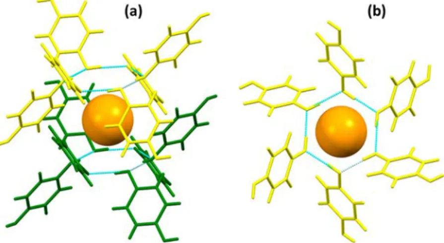
α-form) can be converted, in certain conditions, into HQ clathrates (β-form) by encaging a variety of suitable guest species such as methanol, acetonitrile, sulfur dioxide, argon, krypton, xenon, and others.2 A typical HQ clathrate cavity, showing 12 HQ molecules surrounding a spherical guest, is
illustrated in Figure 1. Such cavities are composed of two
interpenetrating (but not interconnected) networks of six HQ molecules, linked together by a characteristic planar hexagonal ring of hydrogen bonds, delimiting the top and at the bottom of the cage (seeFigure 1).
One of the notable and puzzling features of clathrates is the fact that a guest-free structure (i.e., a clathrate-like structure without any guests present in the cavities) can be formed in certain conditions.8−11 Although it is generally admitted that the stability of a clathrate implies the presence of guest molecules in the host framework, evidence of the existence of guest-free structures (i.e.,“empty clathrates”) has been already reported several times in the literature. In the 1950s, the
Received: April 3, 2020
Accepted: July 7, 2020
phenomenon was reported by Evans and Richards, who prepared HQ clathrates without any enclosed gases by cooling a warm HQ alcoholic solution seeded with an argon HQ clathrate crystal.8 Guest-free clathrate structures can be also obtained by progressive heating of HQ gas clathrates until the full release of their guest molecules (e.g., CO2 and Xe).9,10 Indeed, even with gas hydrates, in which the challenge to obtain a guest-free structure is an incredibly difficult task, an “empty hydrate” (analogous to ice XVI) was identified after 5 days of continuous pumping on small particles of neon hydrate.11
It is interesting to note that hydroquinone (HQ) can form gas clathrates directly by gas−solid reactions12 over a wide range of temperatures and at a moderate pressure (a few
MPa)13 in the presence of small gaseous molecules such as
CO2and CH4.12−14When an equimolar CO2/CH4gas mixture
is put in contact with either native HQ or guest-free HQ clathrates, the CO2can be selectively captured, the latter form
being the more selective.10,15 Indeed, the presence of such a structure in an HQ clathrate-based gas separation process is one of the keys to greatly enhancing the selective enclathration toward one of the components in the gas mixture. In addition,
the enclathration kinetics can be significantly enhanced by
optimizing the gas−solid contact area: the larger the area, the faster the kinetics.16,17In one of the authors’ previous studies, HQ-silica composite materials composed of porous silica particles impregnated with HQ were prepared and tested with
pure CO2 and CH4/CO2 mixtures. This material exhibited
faster gas capture kinetics than native HQ.17 However, this type of silica support is not suited to industrial applications, mainly due to its small particle size (500μm at the most). To
overcome this problem, researchers have identified industrial porous alumina particles (with a diameter of 1 to 3 mm) as a potential alternative support for impregnation.
The present study therefore addresses the preparation, characterization, and evaluation (in terms of gas capture kinetics, separation selectivity, and gas storage capacity) of these HQ-alumina composite materials in the presence of pure CO2and an equimolar CO2/CH4gas mixture.
2. EXPERIMENTAL SECTION
2.1. Materials. The porous supports used (see Figure 2a) are spherical activated alumina particles of 1700−3000 μm provided by Axens. HQ with a purity of 99.5 mol % is provided by Acros Organics. The gases used for the experiments (helium, CO2, and an equimolar
CO2/CH4 mixture) are purchased from Linde Gas SA and have a
minimum mole fraction purity of 99.995%. The solvent used for the impregnation experiments is absolute ethanol (purity greater than 99 mol %). Sulfuric acid (purity greater than 99 mol %) is used as a pH regulator for the impregnation solution. Anhydrous sodium sulfite (analytical reagent grade), used as an additive in the impregnation solution during preliminary tests, is provided by Fisher Scientific.
2.2. Apparatuses and Methods. Impregnation Process. The HQ is deposited on alumina supports through wet impregnation.17In short, after a 24 h thermal pretreatment (i.e., drying) of the alumina supports at 423 K in a muffle furnace, the alumina particles are immersed in the impregnation solutionHQ-saturated ethanol, acidified to pH ∼3−4 by a small amount (a few drops) of sulfuric acidat 308 K for another 24 h. The impregnated particles are then filtered and placed in the oven to dry at 308 K for 24 h in ambient conditions (air).
As shown inFigure 2b, we noticed that if the impregnation solution is not acidified, black particles are obtained after drying. We performed a test with these black particles in contact with pure CO2(at 3.0 MPa and 323 K), measuring only the adsorption on the
Figure 1.General views of a typical HQ-clathrate cavity. The 12 HQ molecules forming the cage are colored in yellow (six for the top network) and green (six for the bottom network). The orange sphere is the guest molecule. The hydrogen bonds forming the two hexagonal rings at the top and bottom of the cavity are represented in light blue. (a) 3D view; (b) view down the crystallographic c-axis.
Figure 2.Pictures of (a) the native alumina particles and (b−d) the HQ-alumina composites obtained after drying, using an impregnation solution with (b) no additive, (c) Na2SO3, and (d) H2SO4.
media (i.e., no enclathration). The HQ seems to be totally deactivated and prohibits the enclathration of gas. In addition, on the basis of our previous observations, we can state that (i) single crystals of HQ clathrate obtained from crystallization in ethanol18 or clathrates prepared by gas-phase synthesis with CH4 or CO214 are off-white
opaque crystals after drying; (ii) the tint of HQ silica particles produced by wet and dry impregnation methods varies from white to light beige.17Therefore, we used this qualitative argument to choose the protocol that gives clear colored composites rather than dark or black ones. It is likely that the color of the particles after impregnation is linked to specific interactions and/or reaction of the HQ with the alumina, which may induce oxidation of HQ during the drying step.19 This assumption was corroborated by adding sodium sulfite (Na2SO3,
a reducing agent well-known for its antioxidant properties) to the nonacidified impregnation solution (∼0.5 g for 10 cm3): as shown in
Figure 2c, the addition of sodium sulfite changes the coloration of the HQ-alumina composites obtained after drying from black (without the additive) to brown (with the additive). Among the various tests we carried out, only the acidification of the impregnation solution by sulfuric acid gave the lightest particle tint (light beige), as shown in Figure 2d.
Analytical Techniques. Both the native alumina and HQ-alumina composites are analyzed by means of several complementary analytical techniques in an attempt to cross-correlate the morpho-logical and structural properties of the particles with their efficiency in relation to the targeted application. Scanning electron microscopy (SEM) serves to characterize the surface of the particles, whereas X-ray computed tomography (XCT) is used for nondestructive inspection of the core of the alumina particles and for specifically analyzing the macroporosity of the particles. Nitrogen adsorption− desorption (i.e., gas porosimetry) tests at 77 K are run to characterize
the mesoporosity (pore size of 2−50 nm) of the HQ-alumina composite (i.e., specific area, total pore volume, and pore size distribution). The specific area is determined using the Brunauer− Emmett−Teller (BET) method,20whereas both the total pore volume
and pore size distribution are calculated using the Barrett−Joyner− Halenda (BJH) method.21The density of the native alumina particles was measured by helium pycnometry. Thermogravimetric analysis (TGA) coupled with differential scanning calorimetry (DSC) is used to estimate the HQ content of the HQ-alumina composite material and measure the thermal signatures of the impregnated compounds. Spectroscopic techniques (i.e., Raman spectroscopy and solid-state
13C nuclear magnetic resonance (NMR)), and XRD measurements,
serve to identify the structure of the deposits. Using Raman spectroscopy, both the external surface and the cross-section of the impregnated particles can be investigated. Additional details concerning the apparatuses and methods used in this study are given in theSupporting Information.
Gas Capture Measurements. Both the gas capture kinetics and gas storage capacity of the HQ clathrates are quantified by gravimetric analysis in the presence of pure CO2at 3.0 MPa and 323 K using a
Rubotherm magnetic suspension balance. The same apparatus was used in one of the authors’ previous studies,17and the reader is asked
to refer to the corresponding paper for details on the apparatus and the experimental procedure.
Gas Separation Measurements. The experiments are conducted using an equimolar CO2/CH4gas mixture at 3.0 MPa and 323 K in a
batch hydroquinone clathrate-based gas separation (HCBGS) process at bench scale.22This process consists of afixed bed reactor operating in closed loop mode (filled with the reactive enclathration media). The main instruments of the setup are a regulator expander, a Coriolis massflowmeter, a gas circulator pump, a reactor, two coaxial heat Figure 3.High-resolution FEG-SEM images (obtained with a JEOL microscope) of (a−c) native alumina and (d−f) HQ-alumina composites; images a and d show the entire particle, and b, c, e, and f the particle surface.
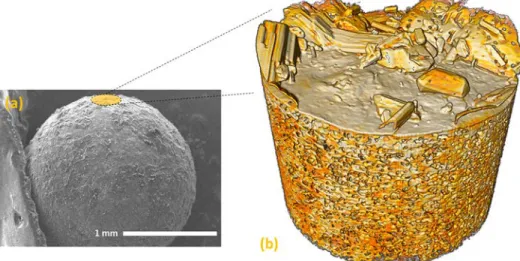
Figure 4.(a) Benchtop SEM image of an HQ-alumina composite (obtained with a Hirox microscope). (b) 3D false color XCT insert (275μm in diameter) showing a detailed view of the HQ crystals scattered on the particle surface.
Figure 5.(a, d) XCT and (b, c, e, f) FEG-SEM images (obtained with a JEOL microscope) of native alumina (left) and HQ-alumina composites (right).
exchangers, and a gas chromatograph (calibrated for quantitative measurements with different CO2/CH4 gas mixtures, with 0.3%
relative uncertainty). In experiments like these in which gas clathrates are formed, both the pressure and gas composition are monitored over time to assess the reaction progress. Mass balance calculations are then performed to estimate the selectivity of the gas separation process toward CO2(i.e., the preferential capture of CO2from the gas
mixture).
3. RESULTS AND DISCUSSION
3.1. Characterizing the HQ-Based Composite Materi-als. Figure 3 shows SEM images of the external surface of native alumina and HQ-alumina composites. The former has a relatively smooth appearance compared to the latter, which is covered with HQ crystals. A detailed 3D-image reconstruction of the HQ-alumina composite surface obtained by XCT is given in Figure 4. Cross-sections orthogonal to the particle surface obtained by XCT (Figure 5a, d) reveal the presence of macroporous cavities in both the native and the composite particles with a size distribution of around 3−4 μm (seeFigure 6b). High-resolution SEM images of typical macropores taken on fractured particles are shown inFigure 5b, c, e, and f. The pore surface exhibits some asperities, but it is impossible to conclude based on the SEM images whether they are simply the rough surface of the alumina or afine layer of HQ crystals.
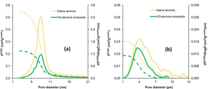
Figure 6presents the pore size distribution and cumulative pore volume of both the native and impregnated particles
obtained by combining measurements of N2 adsorption−
desorption isotherms at 77 K using BET and BJH methods (Figure 6a) and XCT (Figure 6b). Using the density of 3.0423 g cm−3measured for the alumina particles, the macroporosity obtained by XCT is estimated at 0.030± 0.006 cm3g−1for the native alumina particle and at 0.019± 0.006 cm3 g−1for the
HQ-alumina composite. The N2 adsorption−desorption
measurements determined that the mesoporous volume and specific area of the particles after impregnation were 0.22 cm3/ g and 63 m2/g, respectively, hence values around 60% smaller
than those of the native alumina particles (porous volume of 0.55 cm3/g, and specific area of 177 m2/g). As the mesoporous
volume is 15−20 times larger than the macroporous volume,
the overall porosity reduction is close to 60% as well (see
Table 1). The mean (meso)pore size of 9 nm and mean
macropore size of 3−4 μm remained unchanged after the
impregnation process (no peak shift). As already reported in one of the authors’17 previous studies, these observations suggest that either (i) the HQ crystals completelyfill the 9 nm pores, (ii) or some of these pores are clogged by the deposited crystals, or (iii) the pores are partiallyfilled, thereby reducing their height.
The TGA/DSC results presented in Figure 7 show the
thermal behavior from 300 to 900 K of both the alumina
particles (analyzed just before impregnation, i.e., after thefirst 24 h drying phase) and the HQ-alumina composite. The weight loss of the alumina particles after drying is less than 1
wt %. The HQ content (τ) of the HQ-alumina composite is
estimated from the TGA curve usingeq 1:
τ = W −W W i f
f (1)
Figure 6.Pore-size distribution (solid line) and cumulative pore volume (dashed line) as a function of the pore diameter of native alumina (thin yellow lines) and of HQ-alumina composites (thick green lines). (a) Results obtained by N2gas porosimetry; (b) results obtained by XCT.
Table 1. Pore Volume of Native Alumina and of
HQ-Alumina Composites Obtained by N2Gas Porosimetry and
XCT
native alumina
(cm3g−1) HQ-alumina composite(cm3g−1) reduction(%)
mesoporosity 0.55 0.22 60
macroporosity 0.030± 0.006 0.019± 0.006 37
total 0.58 0.24 59
Figure 7.TGA (dashed line) and DSC (solid line) of native alumina particles after drying (fine yellow lines) and HQ-alumina composite (thick green lines).
where Wi is the sample weight (in %) measured after the evaporation of ethanol (Figure 5, point A) and Wfis the weight
(%) after the total mass loss (Figure 5, point B). Based on
Figure 5, Wi and Wfare 99.29 and 74.04%, respectively. The
HQ content of the HQ-alumina composite is therefore estimated atτ = 0.34 ± 0.01 gHQ/gAlumina.
Looking at the DSC curve (solid green line in Figure 7), there is a first light exotherm with an onset temperature of about 348 K, then an endothermal phenomenon takes place
from 360 to 450 K, whereas exothermal trends are finally
observed above 470 K. Thefirst exotherm may be ascribed to
the beginning of partial HQ oxidation or dehydration followed by evaporation of the water formed in this process. In the presence of sulfuric acid and at high temperature, the alumina
media may promote catalytic oxidation/dehydration of HQ.23
The following endothermal and exothermal trends can be ascribed to the sublimation and fusion of HQ, followed by the degradation and volatilization of the residual HQ.17,24,25It is
worth noting that the thermal profile reported is somewhat
similar to that of the HQ-silica composite,17but in this case the aforementioned phenomena are shifted to lower temper-atures. For instance, the endothermal phenomenon starts at 433 K for the silica-based composite (a value around 73 K higher than for the alumina-based composite). This can probably be attributed to the size of the impregnated HQ crystals that ensures better heat transfer (smaller HQ crystals in the case of the HQ-alumina composite), but also because alumina in the presence of sulfuric acid additive is a much more active catalyst than silica.23In addition, from about 500
to 900 Kthe maximum temperaturethe HQ-alumina
composite loses about 10% mass against less than 1% in the case of the HQ-silica composite. This major difference means that the impregnated HQ crystals of the HQ-alumina composite require higher temperatures to empty the
mesopores of the support. The confined porous space appears
to modify the thermodynamic equilibrium properties of the HQ as observed in other systems.26,27All these observations confirm that chemical interactions occur between the HQ and the alumina particles and potentially that HQ crystals are present in the pores.
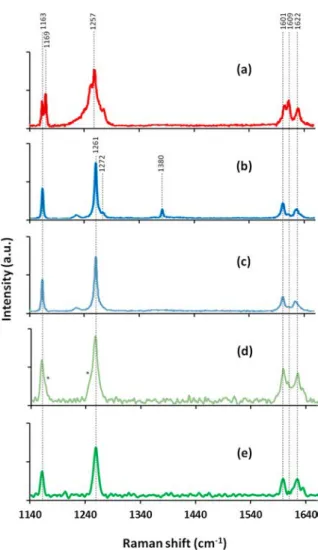
Figure 8d, e presents Raman spectra of both the external surface and the cross-section of the impregnated particles. To make a comparison with other data obtained previously by the
authors, we show the spectra of native α-HQ,15 CO2-HQ
clathrate,14and guest-free clathrate obtained by thermal release
of CO2 from a CO2-HQ clathrate15 in Figure 8a−c,
respectively. Focusing on the range 1100 to 1700 cm−1,
some characteristic differences with the Raman spectrum of
native HQ can be observed. The two C−H bending bands at
1163 and 1169 cm−1in the native HQ spectrum appeared as a
single band at 1163 cm−1 in the HQ-alumina composite
spectrum. The intensities of the two bands at 1252 and 1274 cm−1in the native HQ spectrum are significantly reduced in
the HQ-alumina composite spectrum, and the coupled C−O
and C−C stretching band is shifted from 1257 to 1261 cm−1. In addition, there are characteristic changes in the relative intensities of the three C−C stretching bands at around 1600
cm−1 (these changes are less pronounced in the case of the
composite’s external surface spectrum). Consequently, in comparison to the spectrum previously obtained for a HQ clathrate structure (seeFigure 8b) and with literature data,28 all these differences are in perfect agreement with the signature of the HQ clathrate form in the composite. Note that in the
case of the composite’s external surface spectrum, the slight
shoulders seen both at 1169 cm−1 (on the right side of the
band at 1163 cm−1) and at 1252 cm−1(on the left side of the band at 1261 cm−1) show that traces ofα-HQ are present on the particle surface (see the asterisks inFigure 8d).
So, our Raman spectroscopic data suggest that (i) the external surface is covered with guest-free HQ clathrate crystals
and traces of native α-HQ; (ii) only the guest-free HQ
clathrates are present inside the particle, as only their spectral signature is found on the particle cross-section. In fact,finding a Raman spectroscopic signature of HQ on the cross-section of the impregnated particles is additional proof that HQ is present in the pores of the alumina support core, corroborating
the conclusions made from modifications to the pore-size
distribution and cumulative pore volume between the native and impregnated particles, deduced fromFigure 6. To explain the presence of the spectral signature of a possible guest-free clathrate structure, one could assume that it was initially stabilized by some of the molecules originally present in the solution or in the gas phase during the synthesis. However, no spectral signatures of H2SO4(νH2SO4= 977, 892, 592, and 429
cm−1),29O2(νO2 = 1550 cm−1) or N2 (νN2 = 2326 cm−1)30 were detected by Raman spectroscopy, suggesting that none of
Figure 8.Raman spectra of (a) nativeα-HQ, data from ref15; (b) HQ-CO2clathrate, data from ref14; (c) guest-free HQ clathrate, data
from ref 15; (d) external surface of the HQ-alumina composite particle, the asterisks show slight shoulders at∼1169 and ∼1252 cm−1 visible on the spectra; (e) cross-section of the HQ-alumina composites particle.
these products are present as guests in the final composite material and that this clathrate structure is effectively a guest-free one.
Similarly, the comparison inFigure 9between solid-state13C
NMR analyses made on α-HQ, CO2-HQ clathrates,14 and
HQ-alumina composite clearly reveals the nature of the crystals present in the impregnated particles. In the range of 110−150 ppm, only three peaks are expected in the13C spectra of the β-form of HQ because of the ideal centro-symmetric cage symmetry.31However, the exact chemical shift values of these three peaks vary over a narrow range of values and depend on the nature of the guest and the degree of occupancy of the cages.32The NMR spectra ofFigure 9c effectively exhibit three distinct peaks at 148.1, 117.7, and 115.8 ppm corresponding to the chemical shifts of the HQ clathrates. No guest-molecule signature is measured over the entire spectra, such as, for example, the CO2 signature in the CO2-HQ clathrate at 124 ppm (seeFigure 9b). As shown inFigure 9c, the enlargement
of the peak bases compared to pure CO2-HQ clathrate, the
tiny shoulder distinguishable at 146.5 ppm on the composite spectra (see the asterisk in thefigure), and the merged bases of
the two peaks at 117.7 and 115.8 ppm confirm the presence of traces ofα-HQ, as already found on the particle surface with Raman analysis.
Interestingly enough, the distanceΔ (in ppm) between the
two peaks of the nonsubstituted carbon atoms (between∼115
and 117 ppm) can provide additional elements on the shape of the cavity. As a check, the distanceΔ inFigure 9 is measured
for CO2-HQ clathrates at 2.5 ppm; this is in very good
agreement with the data obtained by Lee et al.,33who found 2.6 ppm for the same system. Concerning the clathrate form found in the composite, the mean separation of these two peaks isΔ = 1.9 ppm, a value slightly higher than those found
by Lee et al. for HQ clathrates formed with CH4 (Δ = 1.7)
ppm and N2(Δ = 1.8 ppm).33Therefore, we can infer from
our NMR results that the guest-free clathrate formed in this composite has a structure close to that of type I HQ clathrates, generally obtained with small guests such as Ar, Kr, Xe, CH4,
and N2, and possessing nondeformed (or only slightly
deformed) cavities.34,35
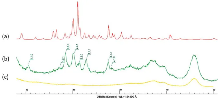
To obtain more precise crystallographic information, we
collected powder XRD data. The results obtained for α-HQ,
native alumina particles, and impregnated particles are
presented in Figure 10. For the HQ that served as the raw
material for the impregnation, the pattern of theα-form of HQ (Figure 10a) is easily identified, with lattice parameters calculated to be a = b = 38.330(14) Å and c = 5.6450(22) Å in the space group R3. Concerning the impregnated particles, the analysis was performed 2 years and 6 months
later than the first set of analyses, on the same batch of
impregnated particles (stored in a closed plastic bag, away from light, under ambient temperature and pressure con-ditions). The particles were ground in a mortar and the
powder obtained was analyzed immediately by XRD. InFigure
10b, the pattern obtained clearly shows the signature of HQ clathrates (i.e., theβ-form),36superimposed onto that of the
amorphous alumina support (Figure 10c). The lattice
parameters are calculated to be a = b = 16.469(20) Å and c = 5.5197(59) Å in the space group R3, in good agreement with the very sparse data reported in the literature for guest-free HQ clathrate structures (a = b = 16.613(3) Å and c = 5.4746(5) Å
Figure 9. 13C NMR spectra: (a) native α-HQ, (b) CO2-HQ
clathrate,14and (c) HQ-alumina composite.
in Mak and Lam (2004),34and a = b = 16.60(1) Å and c = 5.52(1) Å in Han et al. (2012)36). These lattice parameter values confirm that the guest-free clathrate structure formed in this composite may be of type I, with no (or only slight) lattice distortion of the cavity,37in perfect line with our conclusions from NMR measurements. Actually, one of the most interesting features revealed by this XRD analysis is that the guest-free clathrate structure formed during the impregnation process is very stable, as it is still present in the particles more than 2 years after their synthesis. However, the reasons why this could happen have not yet been elucidated. The specific molecular arrangement of the HQ molecules might be related
to specific interactions occurring between the HQ and the
alumina support, or to confinement effects into the pores.
Further investigations are necessary to clarify this point. 3.2. Use of Based Composite Materials. The HQ-alumina composite materials are used to perform CO2capture experiments at 3.0 MPa and 323 K. The composite captured around 0.45 molCO2/kgMedia of CO2 after about 10 days on
stream. Note that, knowing the HQ content of the composite (0.34 gHQ/gAlumina) and the maximum gas storage capacity of HQ (3.03 molGAS/kgHQ), calculated on the basis of the general
HQ clathrate stoichiometry of 1 molecule of gas per 3 molecules of HQ1,2), the maximum gas storage capacity of the HQ-alumina composite is an estimated 0.77 molGAS/kgMedia.
The CO2adsorption capacity of the native alumina particles
is also measured. The equilibrium plateau is reached in 6± 3
min and a storage capacity of 1.48 molCO2/kgAlumina is
measured. As a result, considering these adsorption data for the native support, the amount of gas captured by adsorption on the HQ-alumina composites is graphically estimated at 0.06 molCO2/kgMedia. This amount of gas is subtracted from the total
amount of CO2captured by the composite materials, so that
only the effect of the HQ crystals present on the alumina
particles is considered (i.e., to monitor only the CO2capture
kinetics generated by the enclathration reaction). The methodology and hypothesis underlying this calculation were validated in one of the authors’ previous studies.17In short, the main assumptions are (i) the kinetics of CO2adsorption on the
HQ-based composite are much faster than the enclathration kinetics, meaning that the amount of gas adsorbed and the amount of gas enclathrated can be differentiated, and (ii) the time needed to reach the equilibrium adsorption plateau is the same for both the native support and the HQ-based composite. The results obtained with the alumina composites are first compared with those of silica-based composites and then with
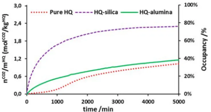
those of powdered native HQ (Figure 11). As previously
observed for HQ-silica composites, the induction time (i.e., the time needed to initiate the HQ clathrate formation) can be done away with by using HQ-alumina composites. The enclathration rate (rc) is 1.6 mmolCO2/(kgHQ min), and the
characteristic time (tc50) needed to attain a clathrate occupancy
of 50% is about 8 days, which is a slight improvement
compared to powdered HQ (rc of 0.5 mmolCO2/(kgHQ min)
and tc50of 9.1 days). It is clear, however, that the HQ-alumina
composites cannot compete in terms of enclathration kinetics with HQ-silica composites (rcof 19 mmolCO2/(kgHQmin) and
tc50of 0.4 days). The presence of guest-free HQ clathrates in
the HQ-alumina composites does not seem to have any
significant effect on the enclathration kinetics. The gas-HQ
contact area available for enclathration is probably not big enough to allow any substantial improvement in terms of kinetics compared to the powdered HQ. In addition, as
reported in the literature,38,39 HQ clathrate formation is potentially impacted when it takes place in confined porous space.
To study the potential of these materials for gas separation, we ran HCBGS experiments on the HQ-alumina composite materials using an equimolar CO2/CH4gas mixture at 3.0 MPa
and 323 K for 4 days. Table 2 presents the main results
deduced from the HCBGS measurements: (i) the mole fraction of CO2in the stored gas (xCO2); (ii) the separation
factor (S.F.CO2/CH4), which quantifies the selectivity of the
separation process toward CO222,40 (the larger the S.F., the
more selective the separation); and (iii) the transient storage capacity (q), i.e., the ratio of the amount of gas stored at time tqto the mass of reactive medium (i.e., HQ + alumina).
(S.F.CO2/CH4) is obtained usingeq 2:
= − − x x y y S. F. /(1 ) /(1 )
CO2/CH4 CO2 CO2
CO2 CO2
(2)
where xCO2 and yCO2are the CO2molar compositions of the
CO2/CH4 gas mixture at time tq in the gas stored in the medium and in the gas phase, respectively.
The performance of the HQ-alumina composites in terms of
CO2/CH4 separation is compared to those of pure HQ
powder, native alumina, native silica, and HQ-silica compo-sites. With the highest S.F.CO2/CH4value, 10.7, the HQ-alumina
composite material exhibits preferential capture of CO2
molecules over time: it exceeds the performance of the HQ-silica composites (S.FCO2/CH4= 6.6) and is approximately twice
as selective as the HQ powder. However, the q value of the
Figure 11.Mole number of CO2captured by enclathration (at 3.0
MPa and 323 K) normalized by the mass of impregnated HQ as a function of time: native HQ powder (dotted red line), HQ-silica composite (dashed purple line), and HQ-alumina composite (solid green line).
Table 2. Material Performance in an HCBGS Process with
an Equimolar CO2/CH4Mixture at 3.0 MPa and 323 K in
Terms of the CO2Mole Fraction in the Stored Gas (xCO2),
Separation Factor (S.F.CO2/CH4), Transient Storage Capacity
(q), and Time Needed to Reach the Transient Storage
Capacity (tq)
media xCO2 S.F.CO2/CH4 q (mol/kgMedia) t q HQ 0.82± 0.04 5.2± 0.6 0.82± 0.05 4 days silica 0.86± 0.08 5.9± 2.4 0.06± 0.01 6± 3 min HQ-silica 0.83± 0.03 6.6± 1.0 0.64± 0.02 4 days alumina 0.83± 0.08 5.5± 2.1 0.63± 0.06 6± 3 min HQ-alumina 0.91± 0.03 10.7± 1.0 0.21± 0.02 4 days
HQ-alumina composites measured after 4 days (0.21 mol/kg) is found to be much lower than those of pure HQ and HQ-silica composites (0.82 and 0.64 mol/kg respectively). It can therefore be concluded that this novel HQ-alumina composite exhibits enhanced selectivity toward CO2, probably related to the presence of guest-free clathrate structures directly formed inside the particle. However, because of its low storage capacity and weak kinetic performances, further material improvements are still necessary before this type of composite can be considered for industrial applications.
4. CONCLUSIONS
This study has provided experimental data on the preparation and characterization of HQ-alumina composite materials able
to form gas clathrates, and their use for CO2 separation.
Characterization of these composites confirmed that HQ was deposited on the alumina particles (both on the external surface and in the particle pores), and revealed very interesting and unusual features. Even if direct crystallization of a guest-free clathrate structure is highly unusual, it is therefore demonstrated using all the characterization results that such a structure is directly crystallized in the core of the alumina particles during the impregnation process. Very interestingly, this guest-free clathrate structure was found to be very stable (over 2 years) in these conditions. On the basis of the kinetic experiments performed using pure CO2, we observed that the
HQ-alumina composites presented a slightly improved enclathration rate compared to HQ powder. In addition,
when these composites are used with an equimolar CO2/CH4
gas mixture, preferential capture of CO2molecules over time is
observed, and the separation factor is approximately double those obtained with HQ powder or HQ-silica composites. The use of these composite materials, allowing the formation of organic clathrates directly by gas/solid reaction (solvent-free), opens up promising avenues for developing alternative
clathrate-based processes for CO2 capture, storage, and
separation. Although the presence of a stable guest-free clathrate structure in these materials is a very interesting option to greatly enhance the selective capture of gaseous substance in HQ clathrates, further improvements to the particle characteristics are still necessary, in particular for boosting the gas capture kinetics and storage capacity, to foresee potential use in practical applications at larger scale.
■
ASSOCIATED CONTENT*
sı Supporting InformationThe Supporting Information is available free of charge at
https://pubs.acs.org/doi/10.1021/acsami.0c06187.
Characterization apparatuses and methods: scanning electron microscopy, helium pycnometry, X-ray
com-puted tomography, nitrogen adsorption−desorption
tests, thermogravimetric analysis coupled with di ffer-ential scanning calorimetry, raman spectroscopy, nuclear
magnetic resonance, and powder X-ray diffraction
(PDF)
■
AUTHOR INFORMATIONCorresponding Author
Jean-Philippe Torré − CNRS, INPT, UPS, Laboratoire de Génie Chimique, Université de Toulouse, Toulouse 31013, France; orcid.org/0000-0001-5735-8626; Email: [email protected]
Authors
Romuald Coupan − E2S UPPA, CNRS, Total, LFCR, Université de Pau et des Pays de l’Adour, Pau 64012, France; Total Research& Technology Feluy, Seneffe 7181, Belgium;
orcid.org/0000-0001-7542-0374
Peter Moonen − E2S UPPA, CNRS, Total, LFCR and E2S UPPA, CNRS, DMEX, Université de Pau et des Pays de l’Adour, Pau 64012, France
Christophe Dicharry − E2S UPPA, CNRS, Total, LFCR, Université de Pau et des Pays de l’Adour, Pau 64012, France;
orcid.org/0000-0002-6318-3989
Frédéric Plantier − E2S UPPA, CNRS, Total, LFCR, Université de Pau et des Pays de l’Adour, Anglet 64600, France Joseph Diaz − E2S UPPA, CNRS, Total, LFCR, Université de
Pau et des Pays de l’Adour, Pau 64012, France
Eve Péré − E2S UPPA, CNRS, IPREM, Université de Pau et des Pays de l’Adour, Pau 64012, France
Abdel Khoukh − E2S UPPA, CNRS, IPREM, Université de Pau et des Pays de l’Adour, Pau 64012, France
Fabrice Guerton − E2S UPPA, CNRS, DMEX, Université de Pau et des Pays de l’Adour, Pau 64012, France
Pascale Sénéchal − E2S UPPA, CNRS, DMEX, Université de Pau et des Pays de l’Adour, Pau 64012, France
Cédric Charvillat − CNRS, INPT, UPS, CIRIMAT, Université de Toulouse, Toulouse, France
Marie-Line De Solan − CNRS, INPT, UPS, Laboratoire de Génie Chimique, Université de Toulouse, Toulouse 31013, France
Complete contact information is available at:
https://pubs.acs.org/10.1021/acsami.0c06187
Author Contributions
The manuscript was written based on contributions from all the authors. All the authors have given their approval to the final version of the manuscript.
Funding
The authors thank the Gas Solutions department of Total S.A. (Exploration & Production Branch) for itsfinancial support. Notes
The authors declare no competingfinancial interest.
■
ACKNOWLEDGMENTSThe authors gratefully acknowledge the work group involved in the ORCHIDS project, the Carnot Institute ISIFoR (Institute for Sustainable Engineering of Fossil Resources), and TOTAL. The tomographic acquisitions described in this article were performed using an instrument provided by TOTAL. We extend our thanks to S. Labat and V. Pellerin from the IPREM laboratory and to G. Guittier and C. Rey-Rouch from the Service Analyse et Procédés (SAP) of the LGC in Toulouse, for their help with the analysis.
■
ABBREVIATIONSHQ, hydroquinone; HCBGS, hydroquinone clathrate-based gas separation; SEM, scanning electron microscopy; FEG, field-emission gun; TGA, thermogravimetric analysis; DSC,
differential scanning calorimetry; NMR, nuclear magnetic
resonance; XCT, X-ray computed tomography; XRD, X-ray diffraction
■
REFERENCES(1) Atwood, J. L.; Steed, J. W. Encyclopedia of Supramolecular Chemistry; CRC Press, Taylor & Francis Group: Boca Raton, FL, 2004; Vol. 1.
(2) Atwood, J. L.; Davies, J. E. D.; McNicol, D. D. Structural Aspects of Inclusion Compounds formed by Organic Host lattices; Academic Press: London, 1984; Vol. 2.
(3) Sloan, E. D.; Koh, C. A. Clathrate Hydrates of Natural Gases, 3rd ed.; CRC Press, Taylor & Francis Group: Boca Raton, FL, 2008.
(4) Rozsa, V. F.; Strobel, T. A. J. Triple Guest Occupancy and Negative Compressibility in Hydrogen-Loaded β-Hydroquinone Clathrate. J. Phys. Chem. Lett. 2014, 5, 1880−1884.
(5) Coupan, R.; Dicharry, C.; Torré, J.-P. Hydroquinone Clathrate Based Gas Separation (HCBGS): Application to the CO2/CH4Gas
Mixture. Fuel 2018, 226, 137−147.
(6) Lee, J.-W.; Poudel, J.; Cha, M.; Yoon, S. J.; Yoon, J.-H. Highly Selective CO Extraction from a Mixture of CO2and H2Gases using
Hydroquinone Clathrates. Energy Fuels 2016, 30, 7604−7609. (7) Chleck, D. J.; Ziegler, C. A. The Preparation and some Properties of Radioactive Quinol-Krypton Clathrate Compounds. Int. J. Appl. Radiat. Isot. 1959, 7, 141−144.
(8) Evans, D. F.; Richards, R. E. Preparation and Magnetic Susceptibility of an Oxygen Clathrate Compound. Nature 1952, 170, 246−246.
(9) Ilczyszyn, M.; Selent, M.; Ilczyszyn, M. M. Participation of Xenon Guest in Hydrogen Bond Network of β-Hydroquinone Crystal. J. Phys. Chem. A 2012, 116, 3206−3214.
(10) Lee, Y.-J.; Han, K. W.; Jang, J. S.; Jeon, T.-I.; Park, J.; Kawamura, T.; Yamamoto, Y.; Sugahara, T.; Vogt, T.; Lee, J.-W.; Lee, Y.; Yoon, J.-H. Selective CO2Trapping in Guest-Free Hydroquinone
Clathrate Prepared by Gas Phase Synthesis. ChemPhysChem 2011, 12, 1056−1059.
(11) Falenty, A.; Hansen, T. C.; Kuhs, W. F. Formation and Properties of Ice XVI Obtained by Emptying a Type sII Clathrate Hydrate. Nature 2014, 516, 231−233.
(12) Lee, J.-W.; Lee, Y.; Takeya, S.; Kawamura, T.; Yamamoto, Y.; Lee, Y.-J.; Yoon, J.-H. Gas-Phase Synthesis and Characterization of CH4-Loaded Hydroquinone Clathrates. J. Phys. Chem. B 2010, 114,
3254−3258.
(13) Coupan, R.; Chabod, M.; Dicharry, C.; Diaz, J.; Miqueu, C.; Torré, J.-P. Experimental Determination of Phase Equilibria and Occupancies for CO2, CH4, and N2 Hydroquinone Clathrates. J.
Chem. Eng. Data 2016, 61, 2565−2572.
(14) Coupan, R.; Péré, E.; Dicharry, C.; Plantier, F.; Diaz, J.; Khoukh, A.; Allouche, J.; Labat, S.; Pellerin, V.; Grenet, J.-P.; Sotiropoulos, M.; Sénéchal, P.; Guerton, F.; Moonen, P.; Torré, J.-P. A Characterization Study of CO2, CH4, and CO2/CH4
Hydro-quinone Clathrates Formed by Gas-Solid Reaction. J. Phys. Chem. C 2017, 121, 22883−22894.
(15) Coupan, R.; Péré, E.; Dicharry, C.; Torré, J.-P. New Insights on Gas Hydroquinone Clathrates Using in Situ Raman Spectroscopy: Formation/Dissociation Mechanisms, Kinetics, and Capture Selectiv-ity. J. Phys. Chem. A 2017, 121, 5450−5458.
(16) Coupan, R.; Torré, J.-P.; Dicharry, C.; Hemati, M.; Plantier, F. Kinetics of CO2 Capture by Hydroquinone Clathrates. Ind. Eng.
Chem. Res. 2018, 57, 8172−8182.
(17) Coupan, R.; Plantier, F.; Torré, J.-P.; Dicharry, C.; Sénéchal, P.; Guerton, F.; Moonen, P.; Khoukh, A.; Kessas, S. A.; Hemati, M. Creating Innovative Composite Materials to Enhance the Kinetics of CO2Capture by Hydroquinone Clathrates. Chem. Eng. J. 2017, 325,
35−48.
(18) Torré, J.-P.; Coupan, R.; Chabod, M.; Péré, E.; Labat, S.; Khoukh, A.; Brown, R.; Sotiropoulos, J.-M.; Gornitzka, H. CO2−
Hydroquinone Clathrate: Synthesis, Purification, Characterization and Crystal Structure. Cryst. Growth Des. 2016, 16, 5330−5338.
(19) Health Council of the Netherlands. Hydroquinone and Benzoquinone. Health Based Recommended Occupational Exposure Limit; Health Council of the Netherlands: The Hague, The Netherlands, 2012; publication no. 2012/27.
(20) Brunauer, S.; Emmett, P. H.; Teller, E. Adsorption of Gases in Multimolecular Layers. J. Am. Chem. Soc. 1938, 60, 309−319.
(21) Barrett, E. P.; Joyner, L. G.; Halenda, P. P. The Determination of Pore Volume and Area Distributions in Porous Substances. I. Computations from Nitrogen Isotherms. J. Am. Chem. Soc. 1951, 73, 373−380.
(22) Coupan, R.; Dicharry, C.; Torré, J.-P. Hydroquinone Clathrate Based Gas Separation (HCBGS): Application to the CO2/CH4Gas
Mixture. Fuel 2018, 226, 137−147.
(23) Pines, H.; Haag, W. O. Alumina: Catalyst and Support. I. Alumina, its Intrinsic Acidity and Catalytic Activity. J. Am. Chem. Soc. 1960, 82 (10), 2471−2483.
(24) de Barros Lima, I. P.; Lima, N. G. P. B.; Barros, D. M. C.; Oliveira, T. S.; Mendonca, C. M. S.; Barbosa, E. G.; Raffin, F. N.; Lima e Moura, T. F. A. d.; Gomes, A. P. B.; Ferrari, M.; Aragao, C. F. S. Compatibility Study between Hydroquinone and the Excipients Used in Semi-solid Pharmaceutical Forms by Thermal and Non-thermal Techniques. J. Therm. Anal. Calorim. 2015, 120, 719−732.
(25) McAdie, H. G. Thermal Decomposition of Molecular Complexes: IV. Further Studies of the [-quinol Clathrates. Can. J. Chem. 1966, 44, 1373−1386.
(26) Cuadrado-Collados, C.; Majid, A.; Martínez-Escandell, M.; Daemen, L.; Missyul, A.; Koh, C.; Silvestre-Albero, J. Freezing/ melting of Water in the Confined Nanospace of Carbon Materials: Effect of an External Stimulus. Carbon 2020, 158, 346−355.
(27) Radhakrishnan, R.; Gubbins, K. E.; Sliwinska-Bartkowiak, M. Effect of the Fluid-wall Interaction on Freezing of Confined Fluids: Toward the Development of a Global Phase Diagram. J. Chem. Phys. 2000, 112, 11048−11057.
(28) Kubinyi, M. J.; Keresztury, G. Infrared and Raman Spectra of Hydroquinone Crystalline Modifications. Mikrochim. Acta 1997, 14, 525−528.
(29) Heilala, B.; Makinen, A.; Nissinen, I.; Nissinen, J.; Makynen, A.; Peramaki, P. Evaluation of Time-gated Raman Spectroscopy for the Determination of Nitric, Sulfuric and Hydrofluoric Acid Concen-trations in Pickle Liquor. Microchem. J. 2018, 137, 342−347.
(30) Akahama, Y.; Kawamura, H. Raman Spectroscopy on High-Pressure Pluids of Molecular Oxygen and Nitrogen. Chem. Phys. Lett. 2004, 400, 326−330.
(31) Mak, T. C. W.; Tse, J. S.; Tse, C.-S.; Lee, K.-S.; Chong, Y.-H. Crystal Structure of a Clathrate inclusion Compound of Hydro-quinone and Hydrogen Sulfide. J. Chem. Soc., Perkin Trans. 2 1976, 2, 1169−1172.
(32) Ripmeester, J. A. Application of Solid State13C NMR to the
Study of Polymorphs, Clathrates and Complexes. Chem. Phys. Lett. 1980, 74, 536−538.
(33) Lee, J.-W.; Choi, K. J.; Lee, Y.; Yoon, J.-H. Spectroscopic Identification and Conversion Rate of Gaseous Guest-Loaded Hydroquinone Clathrates. Chem. Phys. Lett. 2012, 528, 34−38.
(34) Mak, T. C.; Lam, C.-K. Encyclopedia of Supramolecular Chemistry; Atwood, J. L., Steed, J. W., Eds.; Marcel Dekker, 2004; pp 679−686.
(35) Conde, M. M.; Torré, J.-P.; Miqueu, C. Revisiting the Thermodynamic Modelling of Type I Gas-Hydroquinone Clathrates. Phys. Chem. Chem. Phys. 2016, 18, 10018−10027.
(36) Han, K. W.; Lee, Y.-J.; Jang, J. S.; Jeon, T.-I.; Park, J.; Kawamura, T.; Yamamoto, Y.; Sugahara, T.; Vogt, T.; Lee, J.-W.; Lee, Y.; Yoon, J.-H. Fast and Reversible Hydrogen Storage in Channel cages of Hydroquinone Clathrate. Chem. Phys. Lett. 2012, 546, 120− 124.
(37) Torré, J.-P.; Gornitzka, H.; Coupan, R.; Dicharry, C.; Pérez-Rodríguez, M.; Comesaña, A.; Piñeiro, M. M. Insights into the Crystal Structure and Clathration Selectivity of Organic Clathrates formed with Hydroquinone and (CO2+ CH4) Gas Mixtures. J. Phys. Chem. C
2019, 123, 14582−14590.
(38) Casco, M.; Silvestre-Albero, J.; Ramırez-Cuesta, A.; Rey, F.; Jorda, J.; Bansode, A.; Urakawa, A.; Peral, I.; Martınez-Escandell, M.; Kaneko, K.; Rodrıguez-Reinoso, F. Methane Hydrate Formation in
Confined Nanospace can surpass Nature. Nat. Commun. 2015, 6, 6432−6439.
(39) Casco, M.; Rey, F.; Jorda, J.; Rudic, S.; Fauth, F.; Martınez-Escandell, M.; Rodrıguez-Reinoso, F.; Ramos-Fernandez, E.; Silvestre-Albero, J. Paving the way for Methane Hydrate Formation on Metal− Organic Frameworks (MOFs). Chem. Sci. 2016, 7, 3658−3666.
(40) Linga, P.; Kumar, R.; Englezos, P. The Clathrate Hydrate Process for Post and Precombustion Capture of Carbon Dioxide. J. Hazard. Mater. 2007, 149, 625−629.
SUPPORTING INFORMATION
Novel Hydroquinone-Alumina Composites
Stabilizing a Guest-Free Clathrate Structure:
Applications in Gas Processing
Romuald COUPAN
1,2, Peter MOONEN
1,3, Christophe DICHARRY
1, Frédéric PLANTIER
4
, Joseph DIAZ
1, Eve PÉRÉ
5, Abdel KHOUKH
5, Fabrice GUERTON
3, Pascale
SÉNÉCHAL
3, Cédric CHARVILLAT
6,Marie-Line DE SOLAN
7, Jean-Philippe TORRÉ
7 *1. Université de Pau et des Pays de l’Adour, E2S UPPA, CNRS, Total, LFCR, Pau, France
2. Total Research & Technology Feluy, Zone Industrielle Feluy C, Seneffe, Belgium.
3. Université de Pau et des Pays de l’Adour, E2S UPPA, CNRS, DMEX, Pau, France
4. Université de Pau et des Pays de l’Adour, E2S UPPA, CNRS, Total, LFCR, Anglet, France
5. Université de Pau et des Pays de l’Adour, E2S UPPA, CNRS, IPREM, Pau, France.
7. Laboratoire de Génie Chimique, Université de Toulouse, CNRS, INPT, UPS, Toulouse, France.