OATAO is an open access repository that collects the work of Toulouse
researchers and makes it freely available over the web where possible
Any correspondence concerning this service should be sent
to the repository administrator:
[email protected]
This is an author’s version published in:
http://oatao.univ-toulouse.fr/24660
To cite this version:
Truc, Trinh Anh and Thuy, Thai Thu and Oanh, Vu Ke and Hang, To Thi Xuan
and Nguyen, Anh Son
and Caussé, Nicolas
and Pébère, Nadine
8-hydroxyquinoline-modified clay incorporated in an epoxy coating for the
corrosion protection of carbon steel. (2019) Tribology: Materials, Surfaces and
Interfaces, 14. 26-33. ISSN 1751-5831
8-hydroxyquinoline-modified clay incorporated in an epoxy coating for the
corrosion protection of carbon steel
Trinh Anh Truc
a, Thai Thu T
h
u
(
, Vu Ke
O
anh
a, To Thi Xuan Hang
a, Anh Son
Nguyen
8'\Nicolas Caussé
h,
Nadine Pébère
,*• LaboraJOry for Protectlve Coatings, lnstttutt for 'lrq,i<:al Technology, VAST, 18 Ho� Quoc Viet, Hanot Vietnam
b Universlti de Toulouse, CIRIMAT, UPS/INPT/CNRS, P.NSIACET, 4, allée Emile Moruo BP 44362, Toulouse 31432 Cedex 4, France
ARTICLE INFO ABSTRACT
Keywords: Montmorlllonlte
Electrochemlcal lmpedance spectrosCOpy Barrier propertles
Adheslon Corroslcn Inhibition
In the present work, a well-known corrosion inhibitor (8-hydroxyquinoline (8HQ)) was inserted within the montmorillonite plate!ets (8HQ-MMT) and the modified clay was incorporated (3 wt.%) into a solvent-free epoxy coating which was afterwards deposited on carbon steel substrates. First, the inhibitive action of 8HQ was investigated by electrochemical methods carried out on a bare carbon steel rotating disk electrode in a 0.1 M NaO solution. Then, e!ectrochemical impedance measurements were performed to assess the effect of the 8HQ MMT in the epoxy coating for the corrosion protection. The results were compared with a reference sample constituted by the epoxy coating containing an ammonium quaternary salt-modified clay. It was shown that the two coatings presented good barrier properties. Dry and wet adherence measurements revealed an improvement of the adherenœ when the 8HQ-MMT was incorporated into the coating by comparison with the reference sample. It was concluded that the 8HQ mainly had an effect at the metaVcoating interface but its concentration was too low to afford significant corrosion protection of the carbon steel.
1. Introduction
Since the beginning of the 2000s, clay based composite coatings have attracted considerable attention as effective and environmental friendly materials (1 6]. The clays can be incorporated into polymer matrices including epoxy or polyurethane and they offer a significant improvement in various properties, le. mechanical (7 10], thermal stability (11,12], flame retardant (13] and oxygen and moisture barrier
(14 16] in comparison with bull< polymer. Among the clay family, sodium montmorillonite (MMT) is commonly applied in polymer composites. Their specific layered structure makes intercalation/ex foliation of the clay possible and leads to a high cation exchange ca pacity and to a high surface area, explaining the use of clays as re inforcing fillers for polymers (17 19]. However, due to their hydrophilic property, the clays dispersion in an organic phase is gen erally limited and the MMT platelets tend to aggregate; hence, to obtain both a good cornpatibility with the organic matrix and the expansion of the stacked layers, the clay is often modified with hydrophobie corn pounds, such as alkyl (or benzyl) ammonium cations, which can be easily exchanged with organic onium ions on the gallery surfaces [8]. Other treatments, le. phosphonium surfactants, organo silane,
• Corresponding author.
hyperbranched polymers have been developed in academic researches for various applications of polymer nanocomposites (20 23].
For the corrosion protection, MMT was also used as nano containers to introduce inhibitors into the polymer matrix. The aim is to avoid inhibitors interaction with the matrix, particularly for organic corn pounds. Recently, Ghazi et al have intercalated benzimidazole and zinc cations in the MMT galleries for the corrosion protection of mild steel by an epoxy ester coating. The modified clay gave a promising active properties for the corrosion protection by the formation of insoluble complexes in artificial defects (24]. Sari et al. used MMT and graphene oxide nanoclays mixtures. The clay functionalization with aminosilane and 1,4 butanediol diglycidyl ether significantly improved the protec tion performance of an epoxy coating (25]. In previous studies, our group have a1so used MMT to incorporate organic inhibitors, such as amino trimethylphosphonic acid or indole 3 butyric acid, into a sol vent epoxy resin for corrosion protection of carbon steels (26 28]. The presence of modified MMr enhanced the barrier properties of the epoxy resin and improved the corrosion protection thanks to the presence of the organic molecules at the metal/coating interface.
In the present work, a natural MMT was modified by 8 hydro xyquinoline (8HQ) and then, the modified MMT (8HQ MMT) was
E-mail address: [email protected] (N. Pébère).
mixture. The pre polymer mixtures were applied on the XC35 carbon steel sheets by spin coating with a speed of 600 rpm during 90 s. After drying at room temperature for 24 h, the coatings were 30 ± 1μm thick (measured by Minitest 600 Erichen digital meter).
2.4. Analytical characterizations
The crystalline structure of the MMT, the AA MMT and the 8HQ MMT were characterized by x ray diffraction (XRD, Siemens dif fractometer D5000) with Cu Kαradiation (λ = 1.54 Å).
FTIR spectra of the 8HQ, the 8HQ Fe chelate and the black products removed from the carbon steel electrode surface after 20 h of immersion in a 0.1 M NaCl solution containing 8HQ were recorded using KBr pellets with a Nexus 670 Nicolet spectrometer equipped with DTGS KBr detector (resolution of 4 cm−1in the 400 cm−1 4000 cm−1region).
Thermogravimetric analysis (TGA) was used to determine thermo degradation of the 8HQ, of the MMT and of the 8HQ MMT. The weight loss curves were obtained using a Setaram thermogravimetric analyser. Experiments were performed in air atmosphere over a temperature range from 20 °C to 1000 °C with a 10 °C/min heating ramp.
The leaching experiments of 8HQ from 8HQ MMT were performed in a 0.5 M NaCl solution. 0.05 g of 8HQ MMT was introduced in 100 mL of 0.5 M NaCl solution. The suspension was stirred all along the dura tion test. A few millilitres of the suspension were periodically removed (from 1 h to 24 h) andfiltered. The released 8HQ in the NaCl solution was determined by UV vis spectroscopy using a GBC Cintra 40 spec trometer atλmax= 240 nm. Calibration curve wasfirst obtained for a series of standard solutions (from 1 mg/L to 10 mg/L of 8HQ). Release experiments were performed in triplicate.
2.5. Electrochemical characterizations
First, the inhibitive efficiency of the 8HQ was determined by clas sical electrochemical measurements with a standard three electrode cell, in which the rod of XC35 carbon steel constituted the working electrode. A platinum grid and a saturated calomel electrode (SCE) were used as counter electrode and reference electrode, respectively. Polarisation curves were obtained using a Solartron 1287 electro chemical interface. Anodic and cathodic polarisation curves were car ried out at a scan rate of 1 mV s−1. Impedance measurements were performed using a Solartron 1287 electrochemical interface connected to a Solartron 1250 frequency response analyser. Impedance diagrams were obtained under potentiostatic regulation, at the corrosion poten tial, over a frequency range of 65 kHz 10 mHz with 8 points per decade, using a 10 mV peak to peak sinusoidal voltage.
The performance of the coatings was assessed by electrochemical impedance spectroscopy (EIS) in a conventional three electrode cell, realized by fixing a cylindrical Plexiglas tube on top of the coated sample, andfilled with a 0.5 M NaCl solution. The surface area of the working electrode was of 28 cm2. An SCE and a Pt sheet were used as reference and counter electrode, respectively. A VMP3 BioLogic (Science Instruments) was used to measure the impedance of the coated samples. Measurements were performed under potentiostatic condi tions, at the corrosion potential (Ecorr) over a frequency range of 100 kHz 10 mHz with six points per decade using 30 mV peak to peak sinusoidal voltage. Electrochemical measurements were obtained in triplicate.
2.6. Adherence and salt spray tests
Pull off test was performed for the dry coatings by Positest Automatic Adhesion Tester following ASTM D4541. Cross cut ad herence test was carried out according to ASTM D3359 method B. The adherence was evaluated using cross hatch cutter (6 blades 1 mm width). A tape with an adhesive strength of 9.5 N per 25 mm (ISO 2409) was immediately applied to the cross cut coating surface. The tape was incorporated in an epoxy resin for the corrosion protection of a carbon
steel. By comparison with our previous studies, the solvent epoxy resin was replaced by a solvent free system [26 28]. 8HQ is known for its chelating properties on different metals and as corrosion inhibitor of copper [29], of magnesium [30], of aluminium [31,32] and of carbon steel [33]. An alkyl quaternary ammonium salt modified MMT was compared with the 8HQ MMT. This organo modified clay is well known to have good dispersion, improving the barrier properties of organic coatings [34,35]. The comparison between the two coatings allowed the barrier effect, due to the modified MMT dispersion into the epoxy matrix, to be differentiated from the role of the inhibitor at the metal/coating interface.
2. Experimental 2.1. Materials
8 hydroxyquinoline (8HQ), was purchased from Alfa Aesar (purity = 99%) and was used as received. In neutral aqueous solution, the 8HQ concentration was chosen near its solubility limit (3 × 10⁻³ M). A Fe(8HQ)
2 chelate was prepared according to the fol lowing protocol [36]: the 8HQ, at its solubility limit, was added to a Fe2SO4 solution (5%) and the solution was stirred until a precipitate was formed. Then, the precipitate was filtered, rinsed with water and ethanol and dried.
Natural montmorillonite (Cloisite® 116) and modified montmor illonite (Cloisite® 30B) were supplied by BYK Southern Clay product. The modified montmorillonite has been treated with an alkyl qua ternary ammonium salt. Cloisite® 116 and Cloisite® 30B were hence forth called “MMT” and “AA MMT”, respectively.
To characterize the inhibitive efficiency of 8HQ, a XC35 carbon steel rod of 1 cm2 cross sectional area was used as working electrode. Its composition in percent weight was C = 0.35, Mn = 0.65, Si = 0.25, P = 0.035, S = 0.035 and Fe to 100. A heat shrinkable sheath left only the tip of the carbon steel cylinder in contact with the solution. The carbon steel samples were abraded with successive SiC papers down to grade 1200 and cleaned in ethanol in an ultrasonic bath and finally dried in warm air. For the coatings, carbon steel sheets (150 × 100 × 2 mm) were used as substrates. They were polished with abrasive papers from 80 to 600 grade and cleaned with ethanol. 2.2. Modification of the clay by the 8HQ (8HQ MMT)
For pH < 5, the 8HQ molecules are protonated (C9H7ONH+). As the MMT is a cationic exchanger, the Na+ and/or the Ca2+ ions in the MMT interlayers can be replaced by the protonated 8HQ. 8HQ MMT was prepared according to the following procedure [26 28]: the 8HQ (7.0 g) was dissolved in a HCl solution (pH = 3). Then, this solution was added drop wise in a suspension of MMT (3.0 g) in distilled water and the mixture was stirred for 24 h at 70 °C. The obtained 8HQ MMT (green precipitate) was collected by centrifugation (speed of 6000 rpm) and washed with water until no chloride was detected in the filtrate using a 0.1 M AgNO3 solution. Finally, the 8HQ MMT was dried at 80 °C in a vacuum oven for 48 h.
2.3. Coating samples
The coating was a solvent free epoxy resin prepared from diglyci dylbisphenol A (Epon 828, from Hexion) as base and a low viscosity modified cycloaliphatic polyamine (Ancamine 2735, from Air Products and Chemicals) as hardener. The AA MMT and the 8HQ MMT were incorporated into the epoxy coating at a concentration of 3 wt.%. In previous works, it was shown that the best corrosion protection was obtained for low clay contents (≤5%) [26,37]. The modified MMT were progressively added into the hardener by ultrasonification. Then, a magnetic stirring was performed for 24 h to obtain a homogeneous
3. Results
First, the inhibitive efficiency of the 8HQ was assessed from the electrochemical measurements. Then, the modifications of the MMT by the 8HQ were investigated by XRD and TGA measurements. The pro tective properties of the solvent free epoxy coating containing the AA MMT or the 8HQ MMT were monitored by EIS measurements during exposure to the aggressive solution. The dielectric constant of the coatings (εw) in wet conditions were determined by using the complex capacitance plots. Finally, adherence and salt spray tests were realised. 3.1. Efficiency of the 8HQ in aqueous solution
First, the electrode surface was observed by optical microscopy before immersion and after 20 h of immersion in the electrolyte with and without 8HQ. The photographs are shown inFig. 1. InFig. 1b and c, the shape of hydrodynamic patterns are observed due to the electrode rotation rate. Without inhibitor (Fig. 1b), the electrode surface was covered by brown corrosion products. Similar photographs, taken in situ, for the corrosion of pure iron in neutral chloride solutions, have shown that with increasing immersion time (20 h), the corrosion led to the formation of porous layers which progressively decreased the active surface area of the bare metal[38]. You et al. have demonstrated, by an in depth analysis of electrochemical and electrohydrodynamical im pedance measurements that the cathodic oxygen reduction occurs through two diffusion processes: one was essentially representative of the mass transport in liquid phase and the second one corresponded to the diffusion across the porous layers of corrosion products. They concluded that the degree of coupling between them was dependent on the immersion time and on the electrode rotation rate[38]. InFig. 1c, black powdered products are present on the carbon steel surface after immersion in the solution containing the 8HQ. The black products were removed from the steel surface and analysed by FTIR spectroscopy. The FTIR spectrum of the black products was compared to those of the 8HQ and of the synthesized chelate Fe(8HQ)2(Fig. 2). The characteristic bands of the spectra are reported inTable 1. For the synthesized chelate and the black products, the spectra present the characteristic bands of the 8HQ molecule: CeO, CeN and C = N at 1107 cm−1, 1277 cm−1 and 1495 cm−1, respectively but the bands are shifted to lower wave number by comparison with the 8HQ spectrum. This shift can be at tributed to the formation of the Fe O bond between ferrous ions and the 8HQ molecule (Fig. 3) which is confirmed by the appearance of a weak band at 523 cm−1for the chelate and the black products on the FTIR spectra[39,40]. Thus, it can be concluded that in the NaCl solution in the presence of the 8HQ, a chelate was formed on the carbon steel surface by reaction between the 8HQ and the Fe2+ions.
The polarisation curves of the carbon steel, obtained with and without 8HQ after 20 h of immersion at the corrosion potential (Ecorr), are presented inFig. 4. In the presence of 8HQ, a slight shift of Ecorr towards more positive value and a decrease of both the anodic and cathodic current densities are observed. The polarisation curves in dicate that 8HQ is a mixed inhibitor acting both on the anodic and cathodic processes.
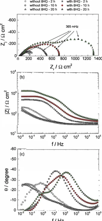
Fig. 5 reports the impedance diagrams (Nyquist and Bode co ordinates) obtained after three immersion times at Ecorr with and without inhibitor. Without inhibitor, the impedance values are low and
the diagrams are little modified during the test. In contrast, in the presence of the 8HQ, the impedance increases when the immersion time increases from 2 h to 20 h, probably due to a higher surface coverage by the 8HQ Fe chelate. In addition, it can be seen that the shape of the diagrams is progressively modified and a second time constant appears in the high medium frequency range. The presence of this time constant might be attributed to the progressive formation of the 8HQ Fe chelate on the steel surface and can explain the anodic and cathodic character of the 8HQ (Fig. 4). In the present work, equivalent circuits were not used to extract impedance parameters because diffusion processes cannot be simply modelled by resistances and capacitances. For the sake of clarity, the polarisation resistance values (Rp) were graphically determined by extrapolation on the real axis at low frequency (Nyquist plots) and used to evaluate the inhibitor efficiency (IE) according to the following equation: = R −R × R IE p 100 i pw pi (1)
Fig. 1. Optical micrographs of the carbon steel surface: (a) before immersion and after 20 h of immersion in a 0.1 M NaCl solution: (b) without inhibitor and (c) with 8HQ (3 × 10⁻³M). Electrode rotation rate of 500 rpm.
removed by a quick pull. The cross cut test was performed before and after 6 h of immersion in distilled water after carefully removing the water excess with tissue paper.
Salt spray test was performed according to ASTM B117 using a Q FOGCCT 600 chamber. Scribes were made on the samples before ex posure to the salt spray. The specimens were placed in the salt spray chamber (angle of 20°). A solution of 5% NaCl was sprayed on the samples (T = 35 °C). The spraying was maintained for the duration of the test. The samples were observed at the end of the test (240 h).
� (b)
2000 1500 1000
Wavenumber / cm-
1500
Fig. 2. FTIR spectra of: (a) SHQ, (b) synthesized SHQ-Fe chelate and (c) black products removed from the carbon steel surface.
Table 1
Characteristic bands of FTIR spectra obtained for SHQ, synthesi7.ed SHQ-Fe chelate and black prod ucts taken from the carbon steel electrode surface.
Bond SHQ (cm 1) SHQ-Fe chelate Blaclc products on the electrode
Fe 0 C O 1097 C N 1288 c�N 1508 (cm 1) (cm 1) 523 110'7 1277 1495 523 1108 1277 1496
w
+
Fe'•
OH
Fig. 3. Schematic illustration of the chelate formation between SHQ and fer rous ions.
"' 10"3
E
<( 10-4
-- --o-- · without 8HQ
- •- · with 8HQ
,J:)o-0o.00
....,0 ...
0
b
,
o.-,.o
--.9 •
•
'o
• "0.0... .._ ·o.o
ô••.:o-o , •
.
...
.
, ,
�• I 'llllllf,•�--�
1. ,,
1 ,, 1 ,, 1 110���-��-��---��-��-��
-1.2
-1.0
-0.8
-0.6
-0.4
-0.2
0.0
E vs. SCE /V
Fig. 4. Polarization curves obtained for the carbon steel electrode after 20 h of immersion in a 0.1 M NaCI solution without inhibitor and with SHQ (3 X 10⁻³M).
Electrode rotation rate of 500 rpm.
Where
R�and
R;are the polarisation resistance values in the presenœ
or in the absence of the inhibitor, respectively. The Rp and IE values are
reported in
Table 2
. The efficiency reached 800/4 after 20 h of immersion
which corresponds to a moderate corrosion inhibition efficiency.
-600
E
o -400
Cl
-
r-,c-200
o wlthout 8HQ -2 h o without 8HQ- 10 h o wlthout 8HQ -20 h200 400
• wlth 8HQ - 2 h • with8HQ-10 h • wlth 8HQ -20 h 365mHz600 800 1000 1200 1400
Zr/
Q
cm
210
4 ..-r�...,,--..,----,--�...,..� ... -�...-...,
(b)
101
10·2
10•1
10
°101
102
10
310
4105
f/Hz
-60
(c)
-50
Q)-40
g' -30
-CD-20
a 0-10
0 00
10·2
10·
110
°10
110
210
310
410
5f/ Hz
Fig. 5. Electrochemical impedanœ diagrams obtained at Ecorr for the carbon
steel electrode for various immersion times in a 0.1 M NaCI solution with and without SHQ (3 x 10⁻³ M): (a) Nyquist plot, (b) impedance mod ulus, (c) phase angle. Electrode rotation rate of 500 rpm .
Table 2
Rp values extracted from the impedance diagrams in Fig. 5 and corresponding efficiency values.
Immersion tlme wlthout SHQ wlth SHQ Inhibitor efficiency R;;' (Q
an
2) � (!lcm2) II!(%)2h 206 11 511 :!: 24 5 9 4
10h 'lf,7 12 741 :!: 50 64 4
:, CO ._
;:;,
ëii C2
C (c) d = 13 A (b) (a) 2 3 4 5 6 7 8 9 1020 / degree
Fig. 6. X-ray diffraction spectra of: (a) MMT, (b) 8HQ-MMT and (c) AA-MMT. 3.2. Characterization of 8 HQ modified clay
Fig. 6 displays XRD patterns of the MMT, the AA MMT and the 8HQ MMT. The peak corresponding to the doo1 plane appears at 28 = 7.o•,
5.2• and 4.8• for the MMT, the 8HQ MMT and the AA MMT, respec tively. The doo1 peak corresponds to the o spacing of the lamellar
structure of the MMT. The o spacing was calculated from Bragg's Iaw:
À= 2dsin0 (2)
where À is the wavelength of the x ray radiation, 8 is the glancing angle and
d
is the interplanar spacing of the clay layers. The calculated o spacing was 13Â, 17 Â and 18À for the MMT, the 8HQ MMT and the AA MMT, respectively. The increase of the doo1 spacing for the 8HQ MMT, compared to the MMT, confirmed the cations exchange by the 8HQ.Fig. 7 shows TGA thermograms for the 8HQ, the MMT and the 8HQ
MMT. Between 40•c and 1oo•c, the 100/4 mass loss for the MMT (Fig. 7b) correspond to the evaporation of adsorbed water. In the temperature range of 400 •c to 700 •c, an additional weight loss of about 8% can be observed, attributed to the dehydration of the re maining water bonded in the crystal lattice (41). For the 8HQ MMT (Fig. 7c), four mass losses are identified. The first one, associated to
0 -20 -40 -60 -80 -100 0
�
0--
-5 Ul.Q
-10 � -15 CO � -20 -25 0 -5 -10 -15 -20 -25 -30 100 300 500 700 (a) 90 (b} 90 (c) 300 500 700 900Temperature / °C
Fig. 7. TGA thermograms of: (a) 8HQ, (b) MMT, and (c) 8HQ-MMT.
100
---Y
�
0 80--"
Q) Ul 60 CO Q)ai
...
40 I 20 CO 0 0 2 3 45
6 t112 /h
112Fig. 8. 8HQ release from 8HQ-MMT in a 0.5 M NaCI solution.
water evaporation is similar to that observed for the MMT (Fig. 7b) but the mass loss is lower (3%). In the 200 700 •c region, three mass losses are seen but the two last ones are not well separated. The mass loss beginning at 220 •c can be associated to the degradation of the 8HQ which is weakly adsorbed on the MMT. The one beginning at 420 •c is attributed to the degradation of the 8HQ inserted in the clay gallery by the ions exchange reaction (42). lt can be seen that the 8HQ degrada tion occurs around 170 •c (Fig. 7a) while for the 8HQ MMT it started at 220 •c. This shift can be explained by the barrier effect of the clay platelets which slowed down the volatile compounds diffusion ( 42). Then, from 500 •c to 700 •c, the mass loss is similar to that observed for the MMT (Fig. 7b). A precise deconvolution of these two last steps was not possible but from the comparison of the two thermograms (Fig. 7b and c), the 8HQ content in the clay platelets is evaluated at about 16 wt. %.
Fig. 8 shows the release of the 8HQ from the 8HQ MMT during 24 h in a 0.5 M NaCl solution. The data are plotted as a function of the square root of time. A linear dependence is observed between 15 min and 24 h indicating that the release of 8HQ was mainly controlled by the inhibitor diffusion within the MMT platelets. After 24 h of immer sion, the 8HQ release reached about 1000/4. The extrapolation of the straight line to t = 0 gives a value of 500/4 of released 8HQ. From these two observations, it can be assumed that the rapid 8HQ release at the beginning of immersion would be due to the presence of the 8HQ molecules weakly adsorbed on the MMT, in agreement with the TGA thermogram (Fig. 7c). After 24 h of immersion, all the 8HQ molecules, incorporated in the MMT platelets, were released into the NaCl solu tion.
3.3. Corrosion protection performance of the coatings
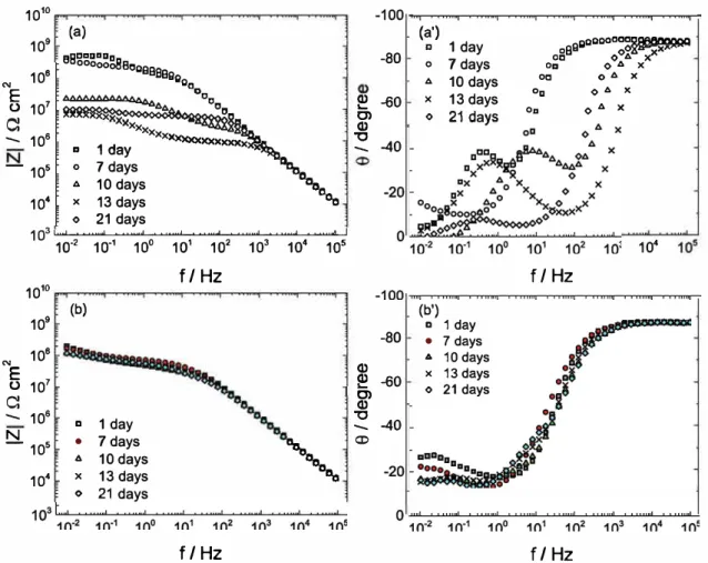
Fig. 9 shows the impedance diagrams obtained for the epoxy coat ings containing the AA MMT and the 8HQ MMT for different exposure times to the NaCl solution. For the coating with the AA MMT, the im pedance diagrams are modified during immersion. The modulus is high at the beginning of immersion (about 4 108 Q cm2), then it decreases for
longer exposure times and slightly increases after 21 days of immersion (Fig. 9a). After 10 days, two time constants are visible: the first one in the high frequency domain represents the properties of the coating and the second one in the low frequency region corresponds to the reaction occurring on the carbon steel surface at the bottom of the pores of the coating (43). This result indicates a degradation of the steel/coating interface and the slight increase of the modulus at low frequency (8 106 0 cm2 after 13 days to 1 107 Q cm2 after 21 days of immersion)
might be linked to the formation of corrosion products at the bottom of the pores. For the epoxy coating containing the 8HQ MMT, in dependently of the immersion time, the diagrams (impedance modulus and phase angle) remain unchanged and only one time constant is observed (Fig. 9b and b'). This result shows that the barrier properties
1010
109
"'
108
E
10
7 0C:
--
106
-105
10
4(a)
eeaaaaaa8
ooo00o 8009999 800 "a�
a 1 day
Xxxxxxxxxxx
'
o 7 days
1\,
6 10 days
Dao
x13 days
°Da
o21 days
1OSL...L��L...�""-�...,_��L...�-'-�-"'-� ...
c....J1� 1� 1� 1� 1� 1� 1� 1�
f /
Hz
1010
109
(b)"'
108
E
10
7 0C:
--
106
1 day
N
a- 105
•
...
7 days
10 days
',
10
4 X13 days
021 days
f /
Hz
�
g>
-80-60
"C
-- -40
-80 Q) Q)�
-60
0) Q)"C
--
-40
a>(a')
a 1 day
o 7days
6 10 days
x13 days
o 21days
(b') a 1 day • 7 days • 10 days x 13 days o 21 days 000aoccc!Ul8111X100Q 0888 o0î�"-· ·
Oa
O 4 X
oa o 6 x Oa O 6 X OaO 6 X
10
4f/Hz
f /
Hz
Fig. 9. Electrochemical impedance diagrams obtained for different immersion times
in
a 0.5 M Na Cl solution for the carbon steel covered by the epoxy coatings containing: (a, a') AA-MMT and (b, b') SHQ-MMT.are maintained during exposure to the NaQ solution without any de gradation of the substrate. For the two coatings, the impedance mod ulus for short immersion are relatively similar (about 2 4 108 Q cm2)
showing similar barrier properties.
From the impedance data, the complex capacitance diagrams can be obtained to determine the dielectric constant of the epoxy coatings as a function of the immersion time in the NaQ solution [ 44). Fig. 10 shows, as an example, the complex capacitanœ plots obtained for the coating containing 8HQ MMT. When the immersion time increases, the coating capacitance values slightly increase from 12.2 nF cm2 after 1 day to
"'E
1.4x10"11 ---��--�--� 1.2x10·11
1.ox10·11•
•
...
X 1 day 7 days 10 days 13 days•
•
... x•
::._ 8.0x10·12 0 21 days•
•
... xoJ-
6.0x10·'2 4.0x10·'2
2.ox10·12 100 kHz\
0.0 L��-�-c:::: C•,,_•;.;...x_,;;o,::::>:,__...L�-��_J 1.0x10·10
1.2x10·10
1.4x10·10
1.6x10·10
C, / F cm
2Fig. 10. Complex-capacitance plots corresponding to EIS spectra (Fig. 9b and b') obtained as a function of immersion lime in a 0.SM NaCI solution for the coating containing SHQ-MMT (the axis are not orthonormal to better visualize the data).
13.3 nF cm2 after 21 days. Tuen, the dielectric constant Cew) was cal
culated from the usual relationship expressing the capacitance of a plane capacitor, i.e.,
(3)
where ew, e0, and 8 are the dielectric constant of the coating under wetcondition, the vacuum permittivity and the thickness of the coating, respectively. The calculated ew values were about 4.5 ± 1 and they little depend on the immersion time (variations are lower than the unœrtainty). The permittivity reported in literature for other dry epoxy coatings is in the range of 3 5 (44,45). Thus, in the present work, the measured permittivity in wet condition Cew) indicated a low water content in the coatings linked to the good barrier properties of the two epoxy coatings.
3.5. Adherence results and salt spray test
The adherence results from the pull off and the cross eut tests are summarized in Table 3. From the pull off test, in dry condition, it can be seen that the strength was two times higher for the coating containing 8HQ MMT compared to the coating containing AA MMT. However, the cross eut test did not allow the two coatings adherenœ to be differ entiated in dry condition and the two coatings have the same classifi cation (5B). In contrast, in wet condition, the epoxy film containing AA MMT was completely removed from the steel surface (OB) while only few coating fragments were removed for the sample containing 8HQ MMT (4B). These results indicate that the adherence of the as prepared coatings containing 8HQ MMT was higher and the adhesion properties were maintained after exposure to the NaQ solution. 8HQ acts as an
adhesion promoter, probably due to its affinity with both the substrate and the epoxy matrix. The adherence improvement in the presence of 8HQ MMT is in agreement with recent results reported on polyepoxy powder coatings containing halloysite or mesoporous silica loaded with 8HQ[46].
The salt spray test was used to evaluate the corrosion performance of the epoxy coatings containing AA MMT or 8HQ MMT. The photo graphs of the samples after 240 h of salt spray exposure are shown in Fig. 11. For the coating containing AA MMT, the delamination is sig nificantly expanded all around the scratch (about 1 cm). For the coating containing 8HQ MMT, no delamination is observed and corroborates the adhesion improvement previously shown (Table 3). In the scratch, the corrosion is similar for both samples.
EIS measurements (both global and local) were performed on scratched coatings to reveal the inhibitive role of the 8HQ on the scratch (results not shown). Whatever the exposure time to the ag gressive solution, no difference between the samples containing the AA MMT and the 8HQ MMT was observed and it was concluded that there was no clear corrosion inhibition due to the 8HQ in the scratches.
4. Discussion
From the impedance results (Figs. 9and10), it was shown that MMT treated with a linear hydrocarbon (AA MMT) or heterocyclic compound (8HQ MMT) and incorporated into a solvent free epoxy coating pro vided good barrier properties. This can be attributed to the good dis persion of the organically modified MMT in the epoxy coating, which slowed down the diffusion of water and aggressive species towards the
metal substrate. However, it can be assumed that the barrier properties would not be sufficient for long term corrosion protection of the carbon steel. From the salt spray test (Fig. 11) and from global and local im pedance measurements on scratched coatings (results not shown), the inhibitive effect of 8HQ MMT incorporated into the epoxy coating was not clearly shown; corrosion products were always visible in the scratches. This could be attributed to the low 8HQ content in the coating (3 wt.% of 8HQ MMT incorporated in the coating corresponds approximately to 0.5 wt.% of 8HQ, as calculated fromFig. 7), which would not be enough to impede the corrosion process, even if all the 8HQ molecules were released from the MMT platelets (Fig. 8).
A higher adherence value in dry condition (pull off strength) was obtained for the coating containing 8HQ MMT (Table 3). In addition, the cross cut test, in wet conditions, confirmed the better adhesion of the coating containing the 8HQ MMT compared to the samples con taining the AA MMT. From the impedance diagrams (Fig. 9b), it was seen that the 8HQ MMT coating performance was maintained during immersion and no delamination was observed during salt spray test (Fig. 11). These two results were attributed to the adhesion improve ment in the presence of the 8HQ MMT.
5. Conclusions
This study focused on the influence of an organic inhibitor (8HQ) incorporated in the MMT platelets to improve the protection of a carbon steel by a solvent free epoxy coating. The 8HQ MMT was compared with an alkyl quaternary ammonium (AA MMT). The impedance results showed the good barrier properties of the epoxy coatings containing the organo modified MMT. The adherence test in dry and wet conditions combined with the salt spray test clearly highlighted the beneficial role of the 8HQ at the steel/coating interface (improvement of the adhe sion). However, the inhibitive role of the molecule was not observed which might be attributed to the low content of the active molecule in the coating.
This study underlined the limitation to use containers, such as MMT, to incorporate organic inhibitors into coatings because the inhibitor concentration would not be sufficient to afford good corrosion protec tion. On the other hand, the containers cannot be introduced at higher contents due to their detrimental effects on the barrier and the me chanical properties[26,37].
Acknowledgments
This work was prepared in the framework of the associated inter national laboratory “Functional Composite Materials (FOCOMAT)” between France and Vietnam.
References
[1] M. Kotal, A. K.Bhowmick, Polymer nanocomposites from modified clays: recent advances and challenges, Prog. Polym. Sci. 51 (2015) 127–187.
[2] O. Zabihi, M. Ahmadi, S. Nikafshar, K.C. Preyeswary, M. Naebe, A technical review on epoxy-clay nanocomposites: Structure, properties, and their applications infiber reinforced composites, Compos. Part B 135 (2018) 1–24.
[3] P. Dhatarwal, R.J. Sengwa, S. Choudhary, Effect of intercalated and exfoliated montmorillonite clay on the structural, dielectric and electrical properties of plas-ticized nanocomposite solid polymer electrolytes, Compos. Commun. 5 (2017) 1–7. [4] Y. Zare, K.Y. Rhee, Multistep modeling of Young's modulus in polymer/clay
na-nocomposites assuming the intercalation/exfoliation of clay layers and the inter-phase between polymer matrix and nanoparticles, Compos. Part A 102 (2017)
Dry condition Wet condition
Pull-off strength (MPa) Cross-cut classification Pull-off strength (MPa) Cross-cut classification
AA-MMT 1.3 ± 0.2 5B – 0B
8HQ-MMT 2.6 ± 0.1 5B – 4B
Fig. 11. Photographs of the carbon steel coated with the epoxy coatings con-taining: (a) the AA-MMT and (b) the 8HQ-MMT after 240 h of exposure to the salt spray test.
Dotted line represents the delaminated surface area. Table 3
137–144.
[5] N.T. Dintcheva, S. Al-Malaika, R. Arrigo, E. Morici, Novel strategic approach for the thermo- and photo- oxidative stabilization of polyolefin/clay nanocomposites, Polym. Degrad. Stab. 145 (2017) 41–51.
[6] A.A. Silva, B.G. Soares, K. Dahmouche, Organoclay-epoxy nanocomposites modified with polyacrylates: The effect of the clay mineral dispersion method, Appl. Clay Sci. 124-125 (2016) 46–53.
[7] K.J. Shah, A.D. Shukla, D.O. Shah, T. Imae, Effect of organic modifiers on dispersion of organoclay in polymer nanocomposites to improve mechanical properties, Polymer 97 (2016) 525–532.
[8] P.C. Le Baron, Z. Wang, T.J. Pinnavaia, Polymer-layered silicate nanocomposites: an overview, Appl. Clay Sci. 15 (1999) 11–29.
[9] F.M. Uhl, S.P. Davuluri, S-C. Wong, D.C. Webster, Organically modified mon-tmorillonites in UV curable urethane acrylatefilms, Polymer 45 (2004) 6175–6187. [10] W. Liu, S.V. Hoa, M. Pugh, Organoclay-modified high performance epoxy
nano-composites, Compos. Sci. Technol. 65 (2005) 307–316.
[11] M. Suguna Lakshmi, B. Narmadha, B.S.R. Reddy, Thermal degradation behaviour and kinetic analysis of epoxy/montmorillonite nanocomposites, Polym. Degrad. Stab. 80 (2003) 383–391.
[12] A. Tcherbi-Narteh, M. Hosur, E. Triggs, S. Jeelani, Thermal stability and degrada-tion of diglycidyl ether of bisphenol A epoxy modified with different nanoclays exposed to UV radiation, Polym. Degrad. Stab. 98 (2013) 759–770.
[13] P. Kiliaris, C.D. Papaspyrides, Polymer/layered silicate (clay) nanocomposites: an overview offlame retardancy, Prog. Polym. Sci. 35 (2010) 902–958.
[14] G. Choudalakis, A.D. Gotsis, Permeability of polymer/clay nanocomposites: a re-view, Eur. Polym. J. 45 (2009) 967–984.
[15] J-K Kim, C. Hu, R.S.C. Woo, M-L Sham, Moisture barrier characteristics of orga-noclay–epoxy nanocomposites, Compos. Sci. Technol. 65 (2005) 805–813. [16] B. Tan, N.L. Thomas, A review of the water barrier properties of polymer/clay and
polymer/graphene nanocomposites, J. Membr. Sci. 514 (2016) 595–612. [17] L. Le Forestier, F. Muller, F. Villieras, M. Pelletier, Textural and hydration
prop-erties of a synthetic montmorillonite compared with a natural Na-exchanged clay analogue, Appl. Clay Sci. 48 (2010) 18–25.
[18] H. He, L. Ma, J. Zhu, R.L. Frost, B.K.G. Theng, F. Bergaya, Synthesis of organoclays: a critical review and some unresolved issues, Appl. Clay Sci. 100 (2014) 22–28. [19] R. Fernández, A.I. Ruiz, J. Cuevas, The role of smectite composition on the
hy-peralkaline alteration of bentonite, Appl. Clay Sci. 95 (2014) 83–94. [20] W. Abdallah, U. Yilmazer, Novel thermally stable organo-montmorillonites from
phosphonium and imidazolium surfactants, Thermochim. Acta 525 (2011) 129–140.
[21] A.N. Bruce, D. Lieber, I. Hua, J.A. Howarter, Rational interface design of epox-y–organoclay nanocomposites: role of structure-property relationship for silane modifiers, J. Colloid Interface Sci. 419 (2014) 73–78.
[22] M.G. Sari, B. Ramezanzadeh, M. Shahbazi, A.S. Pakdel, Influence of nanoclay particles modification by polyester-amide hyperbranched polymer on the corrosion protective performance of the epoxy nanocomposite, Corros. Sci. 92 (2015) 162–172.
[23] P. Anadão, L.F. Sato, R.R. Montes, H.S. De Santis, Polysulphone/montmorillonite nanocomposite membranes: Effect of clay addition and polysulphone molecular weight on the membrane properties, J. Membr. Sci. 455 (2014) 187–199. [24] A. Ghazi, E. Ghasemi, M. Mahdavian, B. Ramezanzadeh, M. Rostani, The
applica-tion of benzimidazole and zinc caapplica-tions intercalated sodium montmorillonite as smart ion exchange inhibiting pigments in the epoxy ester coating, Corros. Sci. 94 (2015) 207–217.
[25] M.G. Sari, M. Shamshiri, B. Ramezanzadeh, Fabricating an epoxy composite coating with enhanced corrosion resistance through impregnation of functionalized gra-phene oxide-co-montmorillonite nanoplatelet, Corros. Sci. 129 (2017) 38–53. [26] T.X.H. To, A.T. Trinh, H.N. Truong, K.O. Vu, J-B Jorcin, N. Pébère, Corrosion
protection of carbon steel by an epoxy resin containing organically modified clay,
Surface Coat. Technol. 201 (2007) 7408–7415.
[27] A.T. Trinh, T.X.H. To, K.O. Vu, E. Dantras, C. Lacabanne, D. Oquab, N. Pébère, Incorporation of an indole-3 butyric acid modified clay in epoxy resin for corrosion protection of carbon steel, Surface Coat. Technol. 202 (2008) 4945–4951. [28] T.X.H. To, A.T. Trinh, M-G Olivier, C. Vandermiers, N. Guérit, N. Pébère, Corrosion
protection mechanisms of carbon steel by an epoxy resin containing indole-3 bu-tyric acid modified clay, Prog. Org. Coat. 69 (2010) 410–416.
[29] G.P. Cicileo, B.M. Rosales, F.E. Varela, J.R. Vilche, Inhibitory action of 8-hydro-xyquinoline on the copper corrosion process, Corros. Sci. 40 (1998) 1915–1926. [30] A.F. Galio, S.V. Lamaka, M.L. Zheludkevich, L.F.P. Dick, I.L. Müller, M.G.S. Ferreira,
Inhibitor-doped sol–gel coatings for corrosion protection of magnesium alloy AZ31, Surface Coat. Technol. 204 (2010) 1479–1486.
[31] S. Marcelin, N. Pébère, Synergistic effect between 8-hydroxyquinoline and benzo-triazole for the corrosion protection of 2024 aluminium alloy: a local electro-chemical impedance approach, Corros. Sci. 101 (2015) 66–74.
[32] F. Chiter, C. Lacaze-Dufaure, H. Tang, N. Pébère, DFT studies of the bonding me-chanism of 8-hydroxyquinoline and derivatives on the (111) aluminum surface, PCCP 17 (2015) 22243–22258.
[33] I.B. Obot, N.K. Ankah, A.A. Sorour, Z.M. Gasem, K. Haruna, 8-Hydroxyquinoline as an alternative green and sustainable acidizing oilfield corrosion inhibitor, Sustain. Mater. Technol. 14 (2017) 1–10.
[34] M.R. Bagherzadeh, T. Mousavinejad, Preparation and investigation of anticorrosion properties of the water-based epoxy-clay nanocoating modified by Na+-MMT and
Cloisite 30B, Prog. Org. Coat. 74 (2012) 589–595.
[35] G. Malucelli, A. Di Gianni, F. Deflorian, M. Fedel, R. Bongiovanni, Preparation of ultraviolet-cured nanocomposite coatings for protecting against corrosion of metal substrates, Corros. Sci. 51 (2009) 1762–1771.
[36] W. Guo, X. Meng, Y. Liu, L. Ni, Z. Huc, R. Chen, M. Meng, Y. Wang, J. Han, M. Luo, Synthesis and application of 8-hydroxyquinoline modified magnetic mesoporous carbon for adsorption of multivariate metal ions from aqueous solutions, J. Ind. Eng. Chem. 21 (2015) 340–349.
[37] M.D. Tomic, B. Dunjic, J.B. Bajat, V. Likic, J. Rogan, J. Djonlagic, Anticorrosive epoxy/clay nanocomposite coatings: rheological and protective properties, J. Coat. Technol. Res. 13 (2016) 439–456.
[38] D. You, N. Pébère, F. Dabosi, An investigation of the corrosion of pure iron by electrochemical techniques and in situ observations, Corros. Sci. 34 (1993) 5–15. [39] K.D. Patel, H.S. Patel, Synthesis, spectroscopic characterization and thermal studies
of some divalent transition metal complexes of 8-hydroxyquinoline, Arabian J. Chem. 10 (2017) S1328–S1335.
[40] K. Zhang, L. Wang, G. Liu, Copper(II) 8-hydroxyquinolinate 3D networkfilm with corrosion inhibitor embedded for self-healing corrosion protection, Corros. Sci. 75 (2013) 38–46.
[41] J.Y. Lee, H.K. Lee, Characterization of organobentonite used for polymer nano-composites, Mater. Chem. Phys. 85 (2004) 410–415.
[42] S. Filippi, M. Paci, G. Polacco, N.T. Dintcheva, P. Magagnini, On the interlayer spacing collapse of Cloisite 30B organoclay, Polym. Degrad. Stab. 96 (2011) 823–832.
[43] L. Beaunier, I. Epelboin, J.C. Lestrade, H. Takenouti, Etude electrochimique, et par microscopie electronique a balayage, du fer recouvert de peinture, Surface Technol. 4 (1976) 237–254.
[44] A.S. Nguyen, M. Musiani, M.E. Orazem, N. Pébère, B. Tribollet, V. Vivier, Impedance study of the influence of chromates on the properties of waterborne coatings deposited on 2024 aluminium alloy, Corros. Sci. 109 (2016) 174–181. [45] G. Bouvet, D.D. Nguyen, S. Mallarino, S. Touzain, Analysis of the non-ideal
capa-citive behaviour for high impedance organic coatings, Prog. Org. Coat. 77 (2014) 2045–2053.
[46] E. Shchukina, D. Shchukin, D. Grigoriev, Effect of inhibitor-loaded halloysites and mesoporous silica nanocontainers on corrosion protection of powder coatings, Prog. Org. Coat. 102 (2017) 60–65.