OATAO is an open access repository that collects the work of Toulouse
researchers and makes it freely available over the web where possible
Any correspondence concerning this service should be sent
to the repository administrator:
[email protected]
This is an author’s version published in:
https://oatao.univ-toulouse.fr/24686
To cite this version:
Billman, Dorrit and Fayollas, Camille and Feary, Michael and
Martinie De Almeida, Célia and Palanque, Philippe Complementary
Tools and Techniques for Supporting Fitness
-for-Purpose of
Interactive Critical Systems. (2016) In: 6th International Working
Conference on Human-Centred Software Engineering International
Working Conference on Human Error, Safety, and System
Development (HCSE + HESSD 2016), 29 August 2016 - 31 August
2016 (Stockholm, Sweden).
Complementary Tools and Techniques for Supporting
Fitness-for-Purpose of Interactive Critical Systems
Dorrit Billman1, Camille Fayollas2, Michael Feary3, Célia Martinie2(✉), and Philippe Palanque2
1 San Jose State University, San Jos, USA [email protected]
2 ICS-IRIT, University of Toulouse, Toulouse, France {fayollas,martinie,palanque}@irit.fr 3 NASA Ames Research Center, Mountain View, USA
Abstract. Sound design of complex, interactive, safety critical systems is very important, yet difficult. A particular challenge in the design of safety-critical systems is a typical lack of access to large numbers of testers and an inability to test early designs with traditional usability assessment tools. This inability leads to reduced information available to guide design, a phenomenon referred to as the Collingridge dilemma. Our research proposes to address parts of this problem with the development of tools and techniques for generating useful information and assessing developing designs early, to minimize the need for late change. More generally, we describe a set of three tools and techniques to support the process of ensuring fitness-for-purpose of complex interactive systems, helping designers focus on interaction across different functions of an overall system. These different tools and techniques support different parts of the overall design and evaluation process, but are focused on improving the coverage and effec‐ tiveness of evaluating interaction.
Keywords: Work analysis and representation · Interactive systems behavior · Complementary approaches · Safety-critical systems · Aviation
1
Introduction
Design of complex, interactive, safety critical systems requires an analysis of both the purpose (mission) the technology is intended to support, the users, and the environmental and social context in which the technology is to be used to determine whether the concept or prototype is fit for its purpose. Early in the process it is easy to make changes to the requirements or design concept, but it may be difficult to determine whether a candidate design or requirement specification will in fact meet the work needs. Later in the process
The rights of this work are transferred to the extent transferable according to title 17 § 105 U.S.C.
there is much more information available, but the cost of change is much greater. This is known as the Collingridge Dilemma [11], which states that when change is easy, information to guide change is scarce; when information is available, change is difficult. In the context of critical systems, the Collingridge Dilemma manifests in two broad challenges, which we will refer to as coverage and effectiveness. The coverage challenge concerns adequacy or sufficiency of the technology to support the work for which it was designed. For example, is the information needed for the task provided and are the actions to be taken supported? Are the needed tasks available at the right time without being locked out? Are actions specified for all reachable conditions? The effectiveness
challenge concerns how much of the technology is actually necessary for the work,
versus technology which is not needed for the work. For example, are information and operators provided that do not support the work? Are multiple, redundant methods provided that do not benefit the work? Does operation of the technology itself add excessive overhead? Quality of how the effectiveness challenge has been addressed might be measured in terms of unnecessary “features” and lines of code or in terms of end user time or effort to accomplish work. Finally, even for technology that roughly provides capabilities sufficient to get the job done, without a great deal of unnecessary elements, the technology can differ in how well the elements are organized or configured. When any of these aspects are poor, the technology will not be well-aligned with the work, and will not be well fit for purpose.
Where work domains are simple, it may be feasible to develop technology that is aligned with the work informally, by relying on design skill and prior experiences. As work and supporting technology becomes more complex, systematic methods supported by appropriate tools become increasingly valuable. In this paper, we propose a process, and three tools and techniques for ensuring that the requirements, design, and resulting system in fact support the intended work missions, and are fit for purpose. The tools and techniques address the Collingridge Dilemma through their intended use early in the design process.
This article is structured as follows. Section 2 presents, after an overview and anal‐ ysis of the existing development processes, a new process for ensuring fitness for purpose of interactive critical systems prototypes. Section 3 presents three tools and techniques for supporting this process, along with its detailed description when using these tools. Section 4 presents the application of the proposed development process to an illustrative example from the commercial aviation domain. Section 5 discusses the complementarity of the three tools and techniques and the perspectives of the proposed approach. Finally, Sect. 6 concludes the paper.
2
Development Processes for Ensuring Fitness for Purpose
of Interactive Critical Systems Prototypes
This section first presents an overview of the existing development processes. From the analysis of these existing processes, we then propose a new process for ensuring fitness for purpose of Interactive Critical Systems prototypes.
2.1 Related Work
Three research strands are relevant to our work. Most of the existing system and software development processes do not include prototyping activities. User centered-design does include prototyping as a key activity in design processes. Work-centered design focuses on analysis of the needs dictated by the work, rather than those based on technology or the user.
Development Processes. Early development process models [21, 28] promoted the construction of reliable software by building the “system right”. To try to address the concern of building the “right system”, the spiral development process promoted by Boehm [5] has introduced the production of specific artifacts called prototypes in order to first identify the adequacy of the current version of the software with clients’ require‐ ments, and second provide a framework for handling explicitly iterations. Such iterative processes were not delivering as expected, as demonstrated by a thorough study of more than 8000 project [6]. As identified in this study, the main drawback of these early software development processes (beyond the inherent difficulty of building large and complex system products) was the difficulty of identifying user needs and of producing software meeting user needs while encompassing ever evolving new technologies. Iter‐ ative or agile approaches, such as Scrum [29], advocate that requirements tuning is performed by means of rapid and systematic iterations. However, even in the last version of Scrum1, there is still no reference to the end user. This has been clearly stated and
identified in [30] where User Centered and Agile approaches where compared and assessed. Beyond that, task/artifact life cycle, as identified in [10], introduces a different perspective on user needs evolution. It argues that providing users with a new tool (even if the tools are perfectly in line with their needs) will change the needs as the work and practice of users will evolve due to this particular new tool. This demonstrates the need to involve end users throughout the development process to validate the systems and to redefine their needs [18]. Another very different problem lies in the iterative nature of the agile and spiral processes. Software can be hard to manage, test, and modify because it has been built by frequently adding new functionalities without following a global and thorough design. While this might not be a big problem when small and rather simple applications are considered, when it comes to large scale and complex systems (as aircraft flight decks) this might have significant impacts both in term of development costs and resources but also in terms of reliability and dependability. To handle such complexity model-based approaches such as UML or [24] provide abstraction and domain specific notations. However, approaches such as Scrum or the Spiral model reject the use of models due to the cost in terms of effort and time.
User-Centered Design Processes. Even though it took a long time to make its way in the area of system and software engineering, the necessity of designing systems and software compliant with user needs and user capabilities recognized much earlier in the area of Human-Computer Interaction. The User Centered Design approach (introduced in [23]) has promoted user-related consideration to the center of the development
1
processes. Several processes have since been proposed to take into account usability while designing an interactive system. Hartson et al. [17] and Collins [12] identified mandatory steps to design usable system. Curtis & Hefley [13] first tried to match soft‐ ware development processes with usability engineering and techniques. Rauterberg [27] identified more precisely design steps to involve end-users in an iterative-cyclic devel‐ opment process. Goränsson et al. [16] proposed a design process centered on usability: “The usability design process is a UCSD approach for developing usable interactive systems, combining usability engineering with interaction design, and emphasizing extensive active user involvement throughout the iterative process”. This work empha‐ sizes that design processes for interactive systems must be highly iterative and must promote multiple designs through evolvable prototypes in order to accommodate requirement changes that result from usability evaluations. However, such processes have put too much emphasis on the user side, forgetting the complex reality of software development.
Further, user involvement and prototyping activities are not enough to ensure that the technology is fit for the intended purpose. Users’ goals and work has to be described and compared with system functions in a systematic way.
Work-Centered Design. Work Focused Design emphasizes the importance of under‐ standing the work to be supported. Cognitive Work Analysis [26, 31] emphasizes the importance of Work Domain Analysis as the first and fundamental step of ecological design [7]. Work Centered Design [8, 14] and related approaches [2, 3] also emphasize the importance of work analysis and representation to guide technology design. Our work shares this orientation, and in this paper we aim to lay out a specific design process and associated tools and methods to provide explicit, structured guidance for designing to fulfill work needs.
2.2 A Process for Ensuring Fitness for Purpose of Interactive Critical Systems Prototypes
The proposed process takes into account several inputs, namely, the extant systems, the work environment, and the mission that has to be performed by the operator. Figure 1
presents an abstract view of this process. It makes explicit the three phases (detailed in the following subsections) that have to be performed before the evaluation, develop‐ ment, and deployment of the interactive critical system:
• Work and task analysis loop; • Early prototyping loop;
• Full-scale software prototyping loop.
The proposed process is complementary with other HCI techniques such as user evaluations. As each of these phases is iterative, several version of prototypes are produced and can be iteratively tested with users before being refined in the next iteration of the loop.
Fig. 1. Process for ensuring fitness for purpose of Interactive Critical Systems prototypes
Work and Task Analysis Loop. The work and task analysis loop aims to specify the scope of work that technology is intended to support (work analysis) and to specify the more specific sequences of actions that will accomplish that work (task analysis). Design and evaluation of technology for safety critical work should be based on the functionality needed for the work. If work needs are not specified, there is no basis to assess whether the technology is fit for the intended purpose. To represent work needs at this level requires specifying the component functions across the scope of work relevant to the design/evaluation goal. An analysis for a flight deck design or evaluation needs to be of broader scope than for (re)design of one part. A component function maps onto a high-level task, or goal, to be accomplished to carry out the needed work.
For work analysis, the level of specification must be fairly abstract, in order to be appli‐ cable across alternative technology designs. To see why applicability across alternative designs is important, consider what is needed from a design and from an evaluation perspec‐ tive. From the design perspective, a characterization of the work that the technology should support should apply across the space of possible designs. The characterization should allow a designer to understand what the space of appropriate solutions might be and consider alternative possibilities; it should provide high-level guidance to the designer during devel‐ opment to ensure that the design does support the work needs. From the evaluation perspec‐ tive, a characterization of the work needs should allow assessment of how and how well one particular design meets the various needs but it should also allow comparison of alternative designs with respect to fitness for purpose.
For task analysis, it is valuable to build a more specific representation of tasks needed to accomplish the work, once technologies and policies for accomplishing the work are specified. A task analysis typically specifies how particular technology (radio commu‐ nication with ATC) or policies (pointing so co-pilot can verify action) are used to build a sequence of actions carrying out a particular work function. The task analysis and task modeling phase aims at understanding and describing user activities. It precisely iden‐ tifies goals, tasks, and activities that have to be done by the operator. Task models bring additional advantages to task analysis: representing the structure of the gathered infor‐ mation about operators’ activities and enabling use of software tools to compute, analyze and simulate these models. When supported by (a) a task modeling notation and (b) a tool featuring human task-refinement (cognitive, motor, perceptive tasks) and complex activity editing and simulation, this step enables qualitative analysis of user or operator tasks.
Prototyping and Requirements Specification Loop. The prototyping and require‐ ments specification loop is usually done by designers. This phase aims at rapidly building first versions of the interactive system and at evaluating and modifying early designs of user interfaces. The result of the evaluation of the final version enables requirement specification for the final device. These requirements will then be used as inputs for the full-scale prototyping loop.
Full-Scale Software Prototyping Loop. The full-scale software prototyping loop is usually done by developers. This phase aims at refining the requirements from the prototyping and requirement specification loop by refining them in a precise and unam‐ biguous way.
The full-scale software prototyping loop produces very high-fidelity prototypes, thus specifying a complete and unambiguous description of the interactive system. This description enables fine tuning these prototypes.
This loop also supports the activity of ensuring conformance and compatibility between the different representations of the interactive system (e.g., the tasks models or work representations and the systems models). Indeed, the full-scale prototype can be compared to the work and task representations of the interactive system, thereby ensuring that the system’s behavior will be fully compatible with user tasks.
The final full-scale software prototype can then be used for the evaluation, devel‐ opment, and deployment of the interactive system.
This process helps to ensure in a systematic way that prototypes are developed taking into account the critical tasks that the users will have to perform, even numerous and complex. With this process, the focus is set on the reliability of the developed interactive system with regards to the work that has to be performed. This process may be applied to safety-critical as well as non-safety-critical systems but, in terms of costs and benefits, is more intended to be applied to interactive systems for which functions are numerous and complex.
3
Tools and Techniques Supporting the Proposed Process
In this section, we first preview the set of tools and techniques that we use to support the proposed process. We first present the MAESTRO work and technology represen‐ tation. Second we present the ADEPT prototyping tool. Third, we present the CIRCUS development environment and its associated notations for full-scale prototyping. The illustrated in Fig. 1 is then expanded to show how these tools and techniques support its different phases.
3.1 MAESTRO Work and Technology Representation
Matrix-Assisted Exploration of Structured Task-Technology Relations and Organiza‐ tion (MAESTRO) is a process and representation to guide development of the (formal or informal) requirement specification. It characterizes what work needs to be done, what information is needed to do the work, and what changes as a result of doing the work. Broadly, it focuses on “usefulness” rather than “usability.” Thus, it is not intended to cover all aspects needed in requirements. It provides guidance both for design and evaluation, helping ensure that designers are building to the criteria on which the result will be evaluated [4].
We decompose work into a set of constituent work functions (roughly, abstract tasks), and into a set of the domain variables, both the information needed as input and the control variables changed as output. The input variables represent the information and resources needed by a function (to accomplish a goal). The output variables represent the changes that are intentionally produced as the result of carrying out the function. In cognitive work, the input variables are primarily information needed for the task and the output variables are actions taken as the result of some decision. In piloting, infor‐ mation such as current wind or airspeed are examples of input variables and control settings such as target altitude or flap position are examples of output variables. The work functions, domain variables, and their relationship can be represented in a matrix. Work functions form one dimension and the input/output variables form the second dimension. Cells in this binary matrix code whether or not a particular variable is relevant to a particular work function as 1 s or 0 s.
3.2 ADEPT
The Automation Design Evaluation and Prototyping Tool (ADEPT) is intended to help designers rapidly build, evaluate and modify interactive prototype automated devices and their user interfaces [15]. It is intended to fill a gap between early storyboarding of a device, and a full-scale software prototype. ADEPT relies on a table based formalism to enable domain experts, who may not have formal programming expertise to define the behavior of the prototype technology. The ADEPT tool can produce a software prototype, but the prototype is only intended to be used to test the behavior of the device, and the result of the evaluation is intended to define the specification for the final device.
3.3 CIRCUS Integrated Development Environment
CIRCUS, which stands for Computer-aided-design of Interactive, Resilient, Critical and Usable Systems, is an integrated development environment embedding both system and task modeling functionalities. The CIRCUS environment targets the following user types: engineers, system designers, and human factors specialists. It aims at helping them to achieve their specific tasks during the design and development of interactive critical systems. CIRCUS embeds features for the formal verification of the system’s behavior as well as features for assessment of compatibility between the user’s task and the system’s behavior. The CIRCUS environment integrates three tools for task modeling, system modeling and their synergistic validation:
• The HAMSTERS (Human-centered Assessment and Modeling to Support Task Engineering for Resilient Systems) notation and its tool (named the same) have been designed to provide support for ensuring consistency, coherence, and conformity between user tasks and interactive systems at the model level [1]. The HAMSTERS notation (a) enables structuring users’ goals and sub-goals into a hierarchical tasks tree in which qualitative temporal relationship among tasks are described by opera‐ tors [20] and (b) encompasses notation elements including a wide range of specialized tasks types, explicit representations of data and knowledge, device descriptions, genotypes and phenotypes of errors, and collaborative tasks. The HAMSTERS tool provides means for editing and simulating HAMSTERS task models.
• The PetShop (Petri Net workshop) tool [25] provides support for creating, editing, simulating and analyzing system models using the ICO (Interactive Cooperative Objects) notation [22]. The ICO notation is a formal description technique devoted to specify interactive systems. Using high-level Petri nets for dynamic behavior description, the notation also relies on an object-oriented approach (dynamic instan‐ tiation, classification, encapsulation, inheritance and client/server relationships) to describe the structural or static aspects of systems.
• The SWAN (Synergistic Workshop for Articulating Notations) tool enables the co-execution of the ICO system models with the corresponding HAMSTERS user’s task models [1]. This is done through the editing of correspondences between system and task models and their co-execution. This co-execution presents several advantages such as helping in guaranteeing the application effectiveness and can be partially automated as presented in [9].
3.4 Process Instantiated with the Set of Notation and Tools
Figure 2 presents the expansion of the process illustrated in Fig. 1 and shows how the tools and techniques we use support its different phases. The work analysis is supported by the MAESTRO tool and technique and this phase leads to work and technology matrices. These matrices can be used as inputs for the task analysis phase, helping by giving a description of work functions that can be used as a high-level representation of user tasks. The task analysis phase is supported by the HAMSTERS tool, and leads to the creation of tasks models. These two representations must be checked in order to ensure their completeness and consistency. Once this is achieved, these two
representations are used to refine the work and mission needs and are used as inputs for the prototyping and requirements specification loop.
Fig. 2. Process for ensuring fitness for purpose of Interactive Critical Systems prototypes instantiated with the set of notation and tools
The prototyping and requirements specification loop is supported by the ADEPT tool. The resulting ADEPT prototypes are analyzed and verified and, once their consis‐ tency and completeness is checked, are used to define the requirements for the interactive system specification. These requirements and ADEPT prototypes are used as inputs for the full-scale software prototyping loop.
The full-scale software prototyping loop is first supported by the PetShop tool (and ICO notation) for the prototyping task. Once the ICO-PetShop prototypes are complete and consistent, they can be used as inputs for the editing of correspondence and co-execution phase (supported by the SWAN tool) enabling to ensure their consistency and completeness with tasks models. Once the ICO-PetShop prototypes are complete and consistent with the tasks models, they can be used for the evaluation, development and deployment of the interactive system.
4
Illustrative Example
We apply the proposed three-phase development process to an illustrative example from the commercial aviation domain. First, we describe the illustrative example. Second, for each of the three phases of the process (i.e., work and task analysis, early prototyping, and full scale software prototyping), we apply our set of tools and techniques, to the illustrative example.
4.1 Illustrative Example Description
For much of a commercial aviation flight, airplane automation draws the targets guiding flight from a flight plan. However, tactical adjustments to the flight are not unusual, and require manual, in-flight entry of the new target values. Frequently, these changes in lateral, vertical, or speed targets are in response to instructions from air traffic control (ATC) to deviate to from the flight plan in response to other traffic. The pilot provides the changed lateral, vertical or speed targets to the aircraft automation through one particular component of the flight deck, which we will refer to as a generic Autoflight Control Interface (ACI). We will illustrate tactical adjustments to flight and use of the ACI to carry out this work as our case study. We use this case study to illustrate how our tools and techniques can be used to:
• represent the work and tasks,
• rapidly define and assess some concept ACI behavior, and • represent and assess interaction with a specific ACI design.
This domain provides a valuable example of system design that had unexpected effects when deployed, due to difficulty aligning the imagined work with the actual operational context.
Work Function Studied in this Illustrative Example. We focus on the descent phase of flight because it has greater the likelihood of deviations from the flight plan, producing higher workload for the pilot. Arrival processes are becoming increasingly complex, in turn imposing increasing workload on the pilot. As airliners near their intended destination to a busy airport, they are usually cleared to fly along a prescribed route known as a Standard Terminal Arrival Route (STAR) to provide an orderly flow of aircraft. The STAR contains lateral and vertical path flight plan information that pilots can enter into the aircraft automa‐ tion to provide precise navigation. If all goes according to plan, the aircraft will fly the exact
lateral and vertical path specified in the STAR, however, in busy airspace it is not uncommon to receive amendments to the flightplan instructions; these clearances specify new limits and restrictions for the airliner. A frequent example is to receive an altitude restriction to ensure that aircraft are safely separated vertically. For our example we will suppose an aircraft is cruising at 33000 ft/10000 m, and is cleared for a STAR which contains vertical flightplan information to 10000 f/3000 m, but is interrupted by Air Traffic Control requesting to not descend below 26000 ft/8000 m.
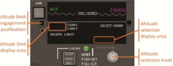
The ACI Device. In order to select and engage an altitude limit value, the pilot will use the ACI device. The one used in this illustrative example is depicted in Fig. 3. With this particular device, the pilot selects an altitude value by rotating the altitude selection knob. This value appears within the altitude selection display area. When the pilot decides that the desired value is selected, s/he engage it as the altitude limit value by pushing the altitude limit engagement pushbutton. This causes the altitude limit to be displayed within the altitude limit display area and passes this value to the aircraft auto‐ mation which restricts the airliner’s descent.
Fig. 3. Panel for altitude management of the ACI device used in this paper.
4.2 Work and Task Analysis
The work and task analysis loop aims to specify the scope of work that the ACI is intended to support (work analysis) and to specify the more specific sequences of actions that will be accomplished with it (task analysis). Both our work analysis and task analysis use the idea of abstract characterizations. Concerning work analysis, an abstract level of representation means that work functions and variables are characterized at a level of abstraction that a subject matter expert would naturally adopt when asked to describe work to be performed at a high-level. Concerning task analysis, an abstract task is one that can be refined in a set of concrete activities. Abstract representation pulls back from the details of how work is done with a specific interface or technology, allowing this to be specified at a later or lower analysis. This is important because it allows comparison across alternative technologies and interfaces and it provides guidance before such details are specified.
Work Analysis. MAESTRO is a process for gathering the work functions and work variables needed in a work domain and representing their relationships in a matrix. Matrix rows represent work functions, columns represent variables (information input
or output controls), and cells represent whether or not the column variable is relevant to the row work function. We use a binary matrix because we want to start with the “simplest possible” representation and because this enables certain methods for finding structure in the relationships between work functions and variables. Of course, other processes and representations could be developed; one extension of our matrix repre‐ sentation would be using cells to code richer information about functions and variables than simply relevant/nonrelevant.
a)
b)
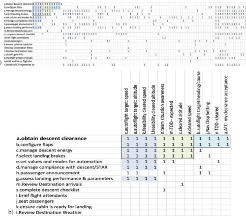
Fig. 4. (a) A high level view of a work matrix showing the patterns of relevant variables (cells with “1”s). Rows show all 19 work functions in Descent phase, and several dozen of the 189 variables as columns. (Variables are truncated.) The intact matrix provides a census of all the information and control variables used in the domain and all the component work functions. The matrix is sorted to focus on the first work function, obtain-descent-clearance (ODC), with rows ordered by how many of ODC’s variables are also relevant to that row’s work function. The matrix also shows that work functions vary greatly in their number of relevant variables. Highlighting shows overlapping clusters of relevant variables. (b) A detail view showing the content of the variables and functions in this group.
Our example matrix shows work functions and variables for the descent phase of flight, with 19 work functions and 189 variables of which 68 are shown. Figure 4-a provides a “bird’s eye view” of the distribution of “1’s” in the matrix showing where a
variable is relevant to a work function. The rows and columns in this matrix view have been manually sorted to place a focal work function, obtain descent clearance, in the first row, to sort the variables this function uses to the left, and to sort the other work functions so that those that also use these variables move to the top. This shows a cluster of work functions and variables that have similar usage. Figure 4-b shows the content of this example cluster. Informally, one can see that there are multiple clusters of mutu‐ ally relevant variables, throughout the matrix. While manual sorting is shown here, we also use clustering and biclustering methods to find related groups [4]. For example, clustering shows that target speed and altitude and cleared speed and altitude are used together in many tasks, which also share additional variables. Note that not all cockpit interfaces group this information together, or clearly distinguish been cleared and current-control altitude across autoflight modes.
To build the matrix in this example, three domain experts (pilots) generated the functions and variables. A human factors expert reconciled the alternative terms and the domain experts reviewed the resulting standardized row and column names. Then the pilots filled in the cells of the standard matrix. We provided a browser-based interface to an underlying database, so users could scroll through sets of variables, selecting those relevant to a work function. The work functions and variables were grouped into labeled categories to aid presentation in the interface, but the categories were not part of the underlying work matrix.
Work analysis can provide input to task analysis by identifying the functions that need to be translated into tasks, accomplished within assumptions about the particular technology and resources available. The variable census could be used to check whether or to what degree the needed information and controls are provided for.
The work matrix provides several ways of providing guidance and of assessing an interaction design. The assessment is made possible because the variables provide a ‘common language’ linking the work and the technology. Just as variable sets are needed for the work, technology provides variable sets for the work, both as input to the operator through displays, and by providing the operator with the means of affecting change through controls. Technology can also be represented in a matrix with variables as columns; matrix rows represent elements within the technology such as a panel on the ACI, or a page on a display for the flight management computer.
The fit of technology to work can be evaluated at the level of individual variables and work functions, or in terms of clusters. Not all relevant variables are necessarily provided by the technology. For example, the ACI panel in Fig. 3 represents several related variables: the currently controlling altitude, the source of the currently control‐ ling altitude or mode (i.e., from flight plan or from pilot’s adjustment), the current alti‐ tude clearance limit, and a “scratch pad” holding a value (such as an issued but not in-use clearance) the pilot has noted but not commanded. The fact that all these variables are represented, and represented together, is a strength of this interface. Alternative designs may not distinguish a “planning” value from a commanded value; or information needed together maybe provided in different components, such as the ACI showing only the mode requested by the pilot but not showing the mode actually controlling the airliner. This example illustrates how a technology assessment can be made at the level of an individual work function.
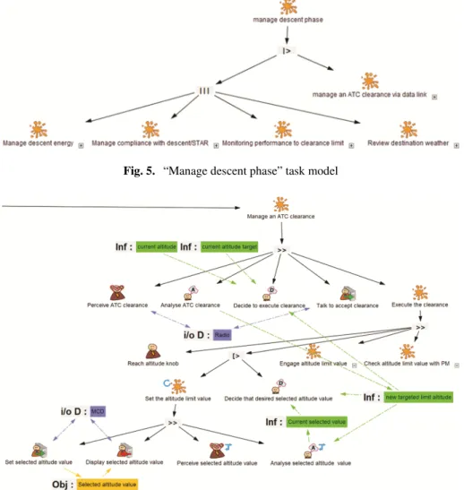
Tasks Analysis. The tasks analysis phase leads to several tasks models representing the different activities that have to be performed by the pilots in order to fly the plane. In the current example, we are more interested in the activities that have to be performed during the descent phase. Figure 5 presents an extract of the task model describing the activities that have to be performed during the descent phase. This model enables to see that the pilot flying the plane (PF) has to perform several concurrent tasks. For readability purposes, we only described here the following tasks: “Manage descent energy”, “Manage compliance with decent/STAR”, “Monitor performance to clearance limit”, “Review destination weather”. These tasks can be further detailed and are thus repre‐ sented in Fig. 5 as folded abstract tasks. While performing these tasks, the pilot can be interrupted by the reception of a clearance (“Manage an ATC clearance” folded abstract task). This task is the one we are focusing on in this example and is detailed in Fig. 6.
Fig. 5. “Manage descent phase” task model
In this task, first the pilot perceives (from the radio) the ATC clearance (“Perceive ATC clearance” perceptive task in Fig. 6), analyzes it, decides to execute it (“Analyze ATC clearance” and “Decide to execute clearance” cognitive tasks in Fig. 6) and notifies the ATC of the clearance acceptance through the radio (“Talk to accept clearance” interactive input task in Fig. 6). Then, the pilot executes the clearance: s/he first set the altitude limit value (“Set the altitude limit value” abstract iterative task) by (in the case of the ACI device presented in Fig. 3) turning the altitude selection knob (bottom right in Fig. 3 and “set selected altitude value” interactive input task in Fig. 6) until the desired value is obtained (“Decide that desired selected altitude value is OK” cognitive task in Fig. 6). Finally, the pilot has to engage the selected altitude value as the limit value (“Engage altitude limit value” abstract task in Fig. 6) and then to check with the pilot monitoring if this value is correct (“Check altitude limit value with PM” in Fig. 6).
Both work analysis and task analysis can aid assessment and refinement of the needs at the level of the work domain. This can be done in terms of coverage, overhead, and organization.
Concerning coverage, for each work function, the technology can be assessed for whether the variables needed for that work function are provided. Generally, higher coverage means that more aspects of the work can be supported by the technology; less, then, must be done in the head, with paper and pencil, or through means outside the technology. Providing a census of the tasks and variables is the simplest and most direct way a work matrix can contribute to design and evaluation. In complementary way, HAMSTERS task models bring an additional support to assess whether all the tempo‐ rally ordered user actions can be performed with the system functions.
Concerning overhead, technology typically requires variables specific to managing that technology and not directly related to the work per se. For example, most require a control for turning the technology on or off. While some overhead is likely necessary, a large number of distinctions and operations in the technology that are unrelated to the work and to the tasks add extrinsic complexity and usually weaken the design.
Concerning organization, the “just right” collection of variables should not only be included in the technology, but they should be organized to align with the work. Ideally, the variables needed for a single work function or task should be accessible together, in space and time. For visual displays, this typically would mean co-location of information in space. For information presented in a multi-page interface, it would mean minimal navigation time. For controls and displays used together, it means that the perception and action modalities do not conflict. The hand and gaze can coordinate. While multiple effectors–hand, voice, feet–might be used on different controls, their use should not conflict, nor make displayed information inaccessible. For simple domains, perhaps a bank teller machine, it may be possible to provide a near-ideal design for each work function. However, for complex domains, the needs of one work function will likely compete with those of another: the ideal grouping of variables for one work function may be different from that of another. Clustering methods can identify groups of vari‐ ables and of tasks that behave similarly; such clusters can prioritize support for variables with similar groupings of variables. Biclustering methods simultaneously group rows by columns and columns by rows, provide a useful way of identifying structure, partic‐ ularly where there are multiple, overlapping groups, possibly with exceptions.
4.3 Prototyping and Requirements Specification
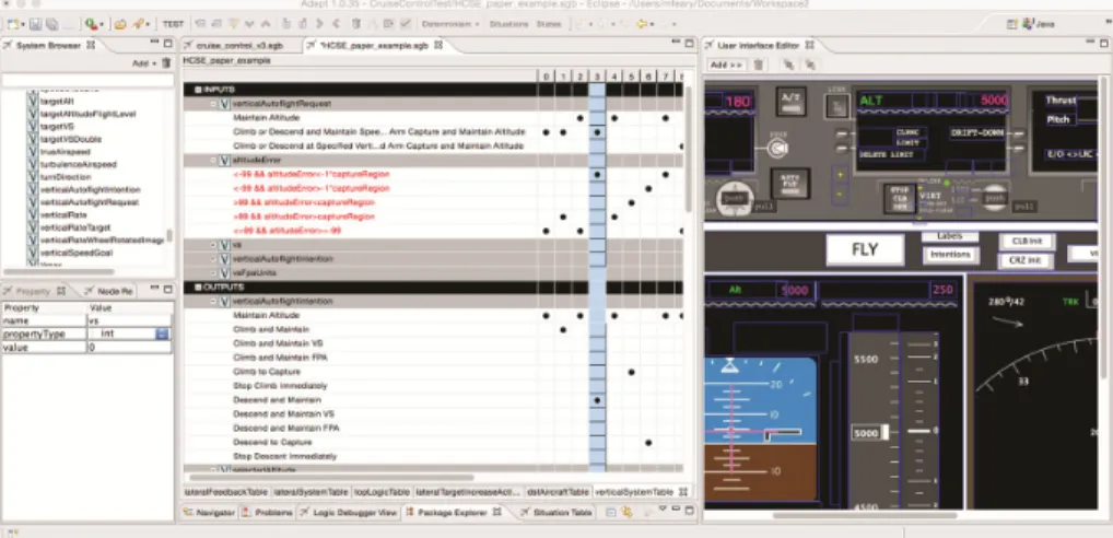
ADEPT is used for the early development of testable prototypes to support designers in the specification of requirements. ADEPT uses an object-oriented tabular format to specify software input conditions and resulting behaviors to reduce programming language knowledge requirements. This enables the domain-expert designer to focus on the development of the prototype. The ADEPT interface (Fig. 7) consists primarily of a software logic editing tool combined with a Graphical User interface editing tool. In the Logic Editor, each set of input conditions and corresponding behavior is represented as a column, and can be read vertically as an “IF” (input condition) “THEN” (software behavior) with “OR” conditions represented as thin grey row dividers, and “AND” conditions as thick grey row dividers associated with variables. ADEPT allows the designer to drag and drop graphical objects from the User Interface editor into the Logic Editor to enable development of prototype interfaces.
Fig. 7. ACI represented in ADEPT
Specifying the ACI device in ADEPT allows us to start to think about requirements for the device. For example, should the device need an altitude to be set below the aircraft altitude before the start of the descent? What should happen if the altitude is set above the aircraft altitude while descending? The ADEPT prototyping environment lets designers with domain knowledge explore these questions, and provides automatic tools to confirm that prototype addresses each combination of input conditions, and that there are no duplicate software behaviors that might lead to confusion when addressing each situation identified.
4.4 Full-Scale Software Prototyping
The full-scale software prototyping loop is divided into two steps: (i) the full-scale soft‐ ware prototyping using the ICO notation (and the PetShop tool), leading to the creation
of ICO prototypes and (ii) its validation through the co-execution of the tasks and systems models. The result of these two steps, in the case of the ACI illustrative example are detailed in the following subsections.
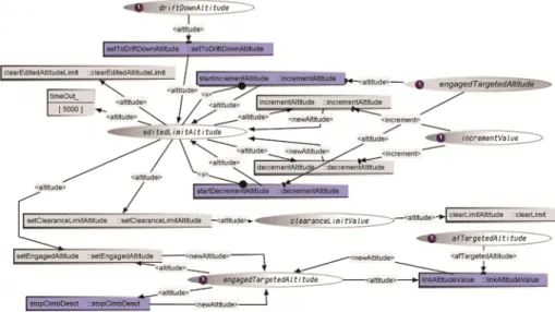
ICO-Petshop Prototypes. Figure 8. presents the ICO model of the behavior of the ACI device (which is presented in Fig. 3). It is important to note that this model is completed by two functions (the activation and rendering functions) that define the connections between this model and the ACI device elements: the activation function defines the connection from the ACI input elements to the model transition firing and the rendering function defines the connection from the state of the model to the ACI output elements. Here we will focus just on the part of the model corresponding to the work presented in Sect. 4.1 and detailed in the task model presented in Fig. 6.
Fig. 8. ICO model of the ACI behavior for altitude management–Rectangles represent transitions (purple ones are enabled and light gray one are disabled); ellipses represent places; purple circles within places represent tokens (the number is the number of tokens in the place). (Color figure online)
The ICO notation is based on high-level Petri nets, its complete definition can be find in the following paper [22]. When the pilot sets the selected altitude value (i.e., using the altitude selection knob of the ACI depicted in Fig. 3), the startIncrementAlti‐ tude transition is fired (if the pilot has incremented the altitude; otherwise, the startDe‐ crementAltitude transition is fired). This firing leads to the creation of a token (containing the value of the current selected value) in the editedLimitAltitude place. The presence of a token in this place leads to the display of the selected altitude value within the altitude selection area. Therefore, the incrementAltitude (resp. decrementAl-titude) transition is fired when the pilot turns the knob in order to increment (resp. decrement) the current selected value, leading to the modification of the value contained in the token within the editedLimitAltitude place. When the pilot pushes the
altitude limit engagement pushbutton, the setClearanceLimitAltitude transi‐ tion is fired, leading to the shifting of the token contained by editedLimitAlti-tude place to the cleranceLimitValue. This token shifting leads to the clearing of the altitude selection area and to the display of the selected altitude value within the altitude limit display area.
Editing of Correspondence and Co-Execution. Once the ICO-PetShop prototype is obtained, the “editing of correspondence and co-execution” step is performed using the SWAN tool. This iterative step leads to a list of correspondences between task-model elements and system-model elements, enabling the co-execution of both task and system models.
To define this list, the developer has first to identify the event sources (transitions of the system model that are connected to the ACI input elements through the activation function) and the renderers (places of the system model that are connected to ACI output elements through the rendering function) of the application. Then, s/he is in charge of putting these elements in correspondence with the elements of the task models: inter‐ active input tasks may be connected to event sources and interactive output tasks may be connected to renderers.
Figure 9 illustrates this editing of correspondences. The first correspondence presents the connection between the “Engage altitude limit” interactive input task and the setClearanceLimitAltitude event handler (corresponding to the setClear-anceLimitAltitude transition. The second correspondence presents the connec‐ tion between the “Display new altitude limit” interactive output task and the clear-anceLimitValue state holder (corresponding to the clearclear-anceLimitValue place).
Fig. 9. Correspondence editing between HAMSTERS models and ICO models
Once this correspondence editing step is done, the developer is able to co-execute the tasks and systems models and check if there are inconsistencies between them (e.g., a task that should be available according to the task model but that is not within the system model). S/he is then able to correct iteratively the tasks or the systems models according to the detected discrepancy. This step helps in guaranteeing the application effectiveness and can be partially automated as presented in [9]. If the effectiveness
requirements are met, the ICO-PetShop prototypes can then be used for the evaluation, development and deployment of the interactive system.
5
Discussion
The process presented here integrates complementary approaches and this integration builds on the strength of each approach and mitigates their weaknesses. Altogether, they cover a wider range of design and evaluation needs, and provide better assurance that technology will be fit for purpose.
5.1 Complementarity
MAESTRO provides an integrated perspective in terms of the resources needed across the domain, spanning both the information and controls needed. Overall, this represen‐ tation is distinctive, however, a compiled list of information needed (as in the columns of the matrix) is similar to the information census proposed within the ecological inter‐ face approach [7]. The work functions, enumerated in the rows, can provide input to a task analysis, as used by HAMSTERS or ADEPT. Although it provides a broad repre‐ sentation of work needs, MAESTRO leaves out many aspects of work, including temporal structure and means-ends relations, even when these are inherent in the work and not a consequence of a particular technology choice. HAMSTERS, in turn provide support for describing and analyzing temporal relationships between the tasks, as well as means-ends relations between required devices to perform an action (or a temporally ordered set of action). While potentially using work matrices as input, HAMSTERS can also provide feedback to the work analysis, for example, by indicating places where a more specific level of representation would help with the design task at hand.
ADEPT can check the logical structure of a design based on a very early prototype. The result of this check can provide assurance that it is worth developing a more complete and detailed prototype, and can guide specification of formal requirements for the finished system. PETSHOP in turn, links prototype development with early evalu‐ ation. SWAN, uses PETSHOP input to feed tools for an analyst to link task descriptions to the operations being carried out by automation (or other computational system), through its interface. This allows the analyst to determine how tasks map onto the capa‐ bilities of the technology, what is covered or omitted, and by what means.
5.2 Perspectives
For each approach that has been integrated in the process, many improvements are envisioned. For instance, for MAESTRO, we have applied and extended biclustering and associated visualization tools to examine the organization implicit in a matrix. However, ways of filtering, comparing, and evaluating clusters would aid interpretation at the organization level. Methods for systematic comparison of the structure in the work matrix with the structure in technology matrix could be implemented in future work. For CIRCUS, integration of tasks and system descriptions could be used for automatic
generation and execution of test scenarios. Analysis of what functions can be automated is an important topic for future research. The proposed overall process and representation flow is novel, and has no integrated use or evaluation has been done. Some individual components have been used helpfully to guide system development, providing an informal evaluation of that component. For example, ADEPT has been used to prototype concepts in aviation automation research and development.
At the process level, providing support (e.g., guidelines and related tools) to the information flow between the phases would help ensure that all the outputs from a phase are taken into account in an appropriate manner and in a systematic way.
6
Conclusion
This article presents a tool-supported approach that aims at ensuring that the require‐ ments, design, and resulting system support the intended work missions, and are fit for purpose. The proposed suite of tools and methods that are proposed for instantiating this process, collectively support design and development of safety-critical software systems. This set of integrated complementary approaches allows designers and devel‐ opers identify information and behaviors that might have been otherwise missed. The approach also supports storage of information gathered and proposes analysis tools to reason about it. Knowledge gained from applying the approach can then be re-injected in the design process to improve the interactive system.
This approach has been defined and applied using a simple case study from the interactive cockpit. Each technique integrated in the approach has been applied to much larger case studies, but work remains to be done to ensure that the approach can scale to operational systems.
It is important to note that interaction techniques in cockpits are going beyond the WIMP paradigm used in the case study, and the approach should be extended to address new interaction techniques for future cockpits such as multi-touch, gestures, and audio feedback.
References
1. Barboni, E., et al.: Beyond modeling: an integrated environment supporting co-execution of tasks and systems models. EICS 2010, pp. 165–174 (2010)
2. Billman, D., et al.: Benefits of matching domain structure for planning software: the right stuff. In: ACM Press, p. 2521 (2011)
3. Billman, D., et al.: Needs analysis and technology alignment method: a case study of planning work in an international space station controller group-part 1. J. Cogn. Eng. Decision Making 9(2), 169–185 (2015)
4. Billman, D., et al.: Representing work for device design and evaluation using biclustering. In: Presented at the Human Factors & Ergonomics Society, Washington, D.C. (2016) 5. Boehm, B.: A spiral model of software development and enhancement. ACM SIGSOFT
6. Boehm, B.: A view of 20th and 21st century software engineering. Invited talk, IEEE International Conference on Software Engineering 2006. http://www.isr.uci.edu/icse-06/ program/keynotes/boehm.html
7. Burns, C.M., Hajdukiewicz, J.R.: Ecological interface design. CRC Press, Boca Raton (2004) 8. Butler, K.A. et al.: Work-centered design: a case study of a mixed-initiative scheduler. In: Proceedings of the SIGCHI Conference on Human Factors in Computing Systems, pp. 747– 756. ACM (2007)
9. Campos, J.C. et al.: Systematic automation of scenario-based testing of user interfaces. In: EICS 2016, pp. 138–148 (2016)
10. Carroll, J.M., et al.: The task-artifact cycle. In: Carroll, J.M. (ed.) Designing Interaction: Psychology at the Human-Computer Interface. Cambridge University Press, Cambridge (1991)
11. Collingridge, D.: The Social Control of Technology. Palgrave Macmillan, London (1981) 12. Collins, D.: Designing Object-Oriented user interfaces. Benjamin Cummings, Redwood City
(1995)
13. Curtis, B., Hefley, B.: A WIMP no more: the maturing of user interface engineering. Interactions 1(1), 22–34 (1994)
14. Eggleston, R.G.: Work-centered design: a cognitive engineering approach to system design. In: Proceedings of the Human Factors and Ergonomics Society Annual Meeting, vol. 47(3), 263–267 (2003)
15. Feary, M.: Automatic detection of interaction vulnerabilities in an executable specification. In: Harris, D. (ed.) HCII 2007 and EPCE 2007. LNCS (LNAI), vol. 4562, pp. 487–496. Springer, Heidelberg (2007)
16. Göransson, B., et al.: The usability design process - integrating user-centered systems design in the software development process. Softw. Process Improv. Pract. 8(2), 111–131 (2003) 17. Hartson, H., Hix, D. Human-computer interface development: concepts and systems for its
management. ACM Comput. Surv. 21(1) 1989
18. Hussain, Z., Slany, W., Holzinger, A.: Investigating agile user-centered design in practice: a grounded theory perspective. In: Holzinger, A., Miesenberger, K. (eds.) USAB 2009. LNCS, vol. 5889, pp. 279–289. Springer, Heidelberg (2009)
19. Martinie, C., et al.: Multi-models-based engineering of collaborative systems: application to collision avoidance operations for spacecraft. EICS 2014, pp. 85–94 (2014)
20. Martinie, C., Palanque, P., Winckler, M.: Structuring and composition mechanisms to address scalability issues in task models. In: Campos, P., Graham, N., Jorge, J., Nunes, N., Palanque, P., Winckler, M. (eds.) INTERACT 2011, Part III. LNCS, vol. 6948, pp. 589–609. Springer, Heidelberg (2011)
21. McDermid, J., Ripken, K.: Life cycle support in the Ada environment. ACM SIGAda Ada Lett. III(1) (1983)
22. Navarre, D., et al.: ICOs: a model-based user interface description technique dedicated to interactive systems addressing usability, reliability and scalability. ACM TOCHI 16(4), 1– 56 (2009)
23. Norman, D., Draper, S. (eds.): User Centered System Design: New Perspectives on Human-Computer Interaction. Lawrence Erlbaum Associates, Hillsdale (1986)
24. Palanque, P., et al.: Supporting usability evaluation of multimodal man-machine interfaces for space ground segment applications using petri net based formal specification. In: SpaceOps 2006 (2006)
25. Palanque, P., Ladry, J.-F., Navarre, D., Barboni, E.: High-fidelity prototyping of interactive systems can be formal too. In: Jacko, J.A. (ed.) HCI International 2009, Part I. LNCS, vol. 5610, pp. 667–676. Springer, Heidelberg (2009)
26. Rasmussen, J., et al.: Cognitive Systems Engineering. Wiley, New York (1994) 27. Rauterberg, M.: An iterative-cyclic software process model. In: SEKE 1992 (1992) 28. Royce, W.: Managing the development of large software systems. In: IEEE Wescon, pp. 1–
9 (1970)
29. Schwaber, K.: Agile Project Management with Scrum. Microsoft Press, Redmond (2004) 30. Sy, D., Miller, L.: Optimizing agile user-centred design. In: CHI 2008 extended abstracts on
Human Factors in Computing Systems (CHI EA 2008), pp. 3897–3900. ACM (2008) 31. Vicente, K.J.: Cognitive work analysis: toward safe, productive, and healthy computer-based