OATAO is an open access repository that collects the work of Toulouse
researchers and makes it freely available over the web where possible
Any correspondence concerning this service should be sent
to the repository administrator:
[email protected]
This is an author’s version published in:
http://oatao.univ-toulouse.fr/22219
To cite this version: Aouadj, Messaoud and Lavinal,
Emmanuel and Desprats, Thierry and Sibilla, Michelle AirNet:
An Edge-Fabric abstraction model to manage
software-defined networks. (2017) International Journal of Network
Management, 27 (6). ISSN 1055-7148
Official URL:
https://doi.org/10.1002/nem.1983
SPECIAL ISSUE PAPER
AirNet: An Edge-Fabric abstraction model to
manage software-defined networks
Messaoud Aouadj I Emmanuel Lavinal
1Thierry Desprats I Michelle Sibilla
IRIT Lab., University of Toulouse, 118Route de Narbonne Toulouse, F-31062, France
Correspondence
Emmanuel Lavina!, IRIT Lab., University of Toulouse, 118 Route de Narbonne, F-31062 Toulouse, France.
Email: [email protected]
1
1INTRODUCTION
Summary
Software-defined networking (SDN) is one of the most significant initiatives to make current networks easier to configure, test, debug, and evolve. Within an SDN ecosys tem, the Northbound interface is used by operators to define policies and to program the control plane, it thus represents a major challenge. Ideally, this northbound inter face should allow adrninistrators to describe, as simply as possible, network services and their interactions, rather than specifying how and on what physical device they need to be deployed. In this article, we propose a new network control language, called AirNet, which is built on top of an abstraction model whose main feature is to provide a clear separation between edge and core network devices. Thus, logical boundaries between different types of policies will exist (control, data, and transport services), ensuring modularity and reusability of the control program. An imple mentation of the AirNet language has also been done, which includes in particular a hypervisor that achieves the composition of the control policies on the virtual net work and their mapping on the physical infrastructure. Finally, several experiments showing promising results have been conducted on different use cases.
With the advent of recent technological innovations such as virtualization, cloud computing, and Internet of Things (loT), the current limitations of network architectures are becorning increasingly problematic for operators and network adrninistrators. 1 Indeed, for several years now, it has been commonly accepted that traditional IP architectures are, on the one hand, particularly complex to configure due to the distributed nature of network protocols and, on the other hand, difficult to evolve due to the strong coupling that exists between the control plane and the data plane of network devices.2
The SDN (Software-defined networking)3 paradigm is a recent approach that aims to respond to this architectural rigidity of current IP networks, in particular by making them more programmable. To do this, the SDN paradigm recommends an archi tecture where the entire control plane of the network is detached from the data plane and logically centralized in a component called controller. Programrning the data plane involves therefore 2 distinct interfaces: (1) the Southbound API (very often imple mented by the OpenFlow protocol, the de facto standard), which enables communication between the controller and lower-level components (ie, switches and other network nodes), and (2) the Northbound API, which enables communication between the controller and higher-level components (ie, SDN applications) that are executed above it and that ultimately control the overall network behavior.
Currently, there are several versions and types of SDN controllers,4-7 each providing a different Northbound interface. Unfor tunately, these interfaces have important limitations, especially the fact that they are specific and low-level APis that offer very few advanced features such as composition of control policies. Thus, the use of an SDN controller has made possible
the programming of a network, but presently, its practical implementation is not necessarily easier than some existing network configuration solutions.
To best achieve SDN objectives, controllers must therefore provide modern programming interfaces to abstract the low-level details of the physical infrastructure and the implementation of the controllers, thus introducing more modularity and flexibility in control programs. These requirements are essential for SDN approaches since the Northbound API is the interface that administrators and operators will use to specify control applications and value-added services.
Drawing on this, recent works on the Northbound API consider network virtualization as an approach that will better achieve these SDN objectives of simplification, modularity, and flexibility of control programs. lndeed, network virtualization8•9 creates abstract visions of the physical infrastructure that expose only the most relevant information for high-level control policies, hiding the complex and dynarnic nature of the physical infrastructure. Moreover, the control programs, or at least a large part of them, can easily be reused on different physical topologies, since their specification bas been performed over virtual topologies. In continuation of our previous work on network control languages, 10•11 we present in this article, AirNet, a new high-level language for programming SDN platforms. To ensure better modularity and flexibility, we put network virtualization at the very heart of our language, and, unlike existing works, we rel y on a new abstraction mode} that explicitly identifies 3 kinds of virtual units: (1) Fabrics to abstract packet transport functions, (2) Edges to support control-plane functions, and (3) Data Machines to provide complex data processing. This abstraction mode} allows Air Net to offer different types of network services (ie, transport, data, static, and dynarnic control services) that can be both composed and chained together to define the overall control policy, as well as reused over different physical infrastructures. Additionally, we have designed and implemented a hypervisor that supports this mode} and achieves its mapping on a physical infrastructure.
The remainder of this paper is organized as follows: In Section 2, existing work on Northbound APis are discussed, then we present in Section 3 the Edge-Fabric abstraction mode} we rely on, and the main motivations behind its proposition. In Section 4, AirNet's general architecture is presented, followed by an overview, in Section 5, of the AirNet language. In Section 6, a description of our hypervisor prototype is presented. Finally, a use case (Section 7) and some experimental results are exposed in Section 8, followed by a conclusion and a brief description of our future work.
2 1 RELATEDWORK
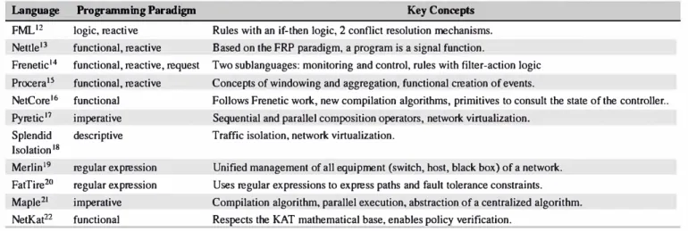
Proposing modern programming languages for SDN platforms has been the subject of numerous research projects. In this section, we present those that we think are the most important and closest to our research problem. Furthermore, it is important to note that this section is not intended to provide a detailed description of each language (largely because it would take too much space ), nor to determine which is the best or the most efficient language, but rather to propose the keys for understanding the main issues and contributions of each one of them. Because of the nature and role of the Northbound API, we believe that it is irrelevant to try to state that such language is better than the others since they are used in various contexts and have different specificities.
Table 1 briefly summarizes these languages and their main contributions. A common point among all these languages is that they all offer abstractions for the OpenFlow23 standard. To do this, each language uses a different programming paradigm.
A higher Level OpenFlow API- The very first languages like FML,12 Nettle,13 and Procera15 are functional and reactive languages. Thus, policies and control programs that are written with these languages take the form of a function, or a composition of functions, that will receive a flow of OpenFlow events (or external events such as an authenti cation of a host), possibly applying transformations on these events and then returning a new flow of events which will often correspond to allow or deny actions, and which will then be used to configure the forwarding tables of the network devices.
This approach makes it possible to bide a large part of the complexity of the interactions between the control program and the physical infrastructure, in particular the construction of the different types of OpenFlow messages or the need to consider the specific API of the underlying controller.
Composition and modularity- Other SDN languages such as Frenetic,14 NetCore,16 and Pyretic17 have been designed to more efficiently express packet forwarding rules. To this end, these languages include predicates and primitives that allow to specify incomplete fùters and to send queries to retrieve statistics about the state of the controller. The control rules for these languages mainly follow a match-actions logic.
Moreover, these languages offer several mechanisms to solve intersection issues between overlapping rules of differ ent control modules, through the introduction of sequential and parallel composition operators (operators integrated,
TABLE 1 Summary of existing network programnùng languages Language FML'2 Nettle13 Frenetic14 Procera15 NetCore16 Pyretic17 Splendid Isolation 18 Merlin19 FatTire20 Maple21 Net.Kat22 Programming Paradigm logic, reacti ve functional, reactive functional, reactive, request functional, reactive functional imperative descriptive regular expression regular expression imperative functional Key Concepts Rules with an if-then logic, 2 conflict resolution mechanisms. Based on the FRP paradigm, a program is a signal function.
Two sublanguages: monitoring and control, rules with filter-action logic Concepts of windowing and aggregation, functional creation of events.
Follows Frenetic work, new compilation algorithms, primitives to consult the state of the controller .. Sequential and parallel composition operators, network virtualization.
Traffic isolation, network virtualization.
Unified management of ail equipment (switch, host, black box) of a network. Uses regular expressions to express paths and fault tolerance constraints. Compilation algorithm, parallel execution, abstraction of a centralized algorithm. Res�cts the KAT mathematical base, enables p<>licy verification.
for example, in the Pyretic language and which we reuse in our contribution). lndeed, on the one band, these operators make it easier to compose the various primitives of a language to obtain more elaborate policies and, on the other band, they also make it possible to compose existing control modules, thus improving the reusability of programs.
Advanced features - Other more advanced features are provided by languages such as FatTire20 that allows adrninistrators to express their network paths while setting fault tolerance requirements. It is then the responsibility of the FatTire runtime to install backup paths to meet these requirements, thanks to new types of forwarding tables introduced in recent versions of the OpenFlow standard.
The Merlin19 language was one of the first attempts to have a unified management environment (in an SDN context) for ail the equipments of a network such as OpenFlow switches, host machines, and various rniddleboxes. To do this, Merlin generates specific code for each device type, while also proposing a possible partial delegation of control of these equipments to an outside tenant.
The Maple21 language introduces an abstraction that allows adrninistrators to see their control program as a single central algorithrn that will be applied to ail packets that enter their network. Thus, an adrninistrator no longer needs to think which packet must go back to the controller and which ones must be processed at the switches, all this is done automatically by the Maple compiler that optimizes this distribution to preserve network performance.
Lastly, the NetKat22 language, whose primitives respect the KAT mathematical basis, allows adrninistrators to check their control programs. lndeed, NetKat is able to formally answer questions such as "Are SSH flows allowed between host A and web server S?"
Network Virtualization -Languages like Pyretic 17 and Splendid Isolation 18 provide support for network virtualization. Using these languages, an adrninistrator can define bis own virtual topologies, according to bis own high-level objectives, and then apply policies on these abstract topologies. The advantage of this approach is that it significantly facilitates the configuration of a network, since the adrninistrator will only consider the information that is most relevant to its overall configuration policy. More importantly, this approach significantly increases the reusability of prograrns as policies are specified on virtual topologies and can subsequently be reused on different physical infrastructure.
Sirnilarly to these related work, we argue that network virtualization approaches are essential for Northbound APis, given the considerable benefits in terms of expressiveness, modularity, and flexibility for control.24 lndeed, having an abstract vision of the physical infrastructure, with only the details that are the most relevant to high-level control policies, greatly simplifies their expression. However, most of these works manipulate abstractions for a specific purpose. For example, Splendid Isolation to isolate control programs or Merlin to solve constraint satisfaction problems on network paths. This results in Northbound interfaces that are oriented towards these specificities. In our case, we target high-level network control policies that are not dedicated to a particular objective and that can take into consideration different types of control and data plane policies.
Therefore, in the next section, we discuss advantages and disadvantages of existing abstraction models, then we detail our proposed abstraction model on which our network programrning language is built.
3 1
CHOOSING THE RIGHT ABSTRACTION MODEL
Today, there are currently 2 main approaches for abstracting the physical infrastructure: (1) the Overlay Network model,25 which consists in overlaying a virtual network of multiple switches on top of a shared physical infrastructure, and (2) the One Big Switch (OBS) abstraction model,26 which consists in abstracting the whole network view in a single logical switch.
Regarding the OBS mode}, it offers a very powerful abstraction level, since all the physical topology is abstracted into one single logical switch on which all hosts are connected. However, this mode} forces network administrators to always use a single router to abstract their physical infrastructure, which can be a very restrictive approach especially when there are underlaying physical constraints that can not or should not be hidden from the control program operating on top of the virtual network (eg, specifying administrative boundaries, network function distribution according to physical topology characteristics). Another drawback is more a software engineering issue. lndeed, using the OBS abstraction involves putting all in-network functions within the same router, thereby resulting in a monolithic application in which the logic of different in-network functions are inexorably intertwined, making them difficult to test and debug.
The Overlay Network model, on the other band, is a very flexible mode}. lndeed, by using virtual switches and links, an administrator bas the possibility to construct various types of virtual topologies that correspond to bis high-level objectives or to the physical constraints that be wishes to take into consideration. However, unlike the OBS model, this mode} makes no distinction between transport policies and more complex network services, although these 2 types of policies resolve 2 different problems. The consequence of this approach is that the definition of complex network services becomes a more difficult task since operators are forced to also consider packet transport issues when specifying their in-network functions, which will naturally lead to control program and network functions that are Jess modular and reusable.
Edge and Fabric: lifting up the modularity at the network control language level. To overcome the limitations of both models, we propose to rely on a well-known idea within the network community, which is making an explicit distinction between edge and core network devices, as it is the case with MPLS27 networks.
Explicitly distinguishing between edge and core functions was also used by Casado et al in a proposai for extending current SDN infrastructures.28 The novelty of our approach is to integrate this concept within the virtual network, thereby lifting it up at the control language level and not limiting it to the physical infrastructure. As illustrated in Figure 1, network operators will thus build their virtual networks using 4 types of abstractions:
• Edges to support complex network functions and services related to the control plane. • Data machines to perform complex operations on packets at the data plane level.
• Fabrics to deal with packet transport issues.
• Hosts and Networks to represent sources and destinations of data flows.
As a consequence, the programming paradigm that we advocate through this edge-fabric abstraction mode} is as follows: Edges will receive incoming flows, apply appropriate control policies that have been previously defined by network operators (using specific primitives that we will present in Section 5), then redirect these flows towards a fabric. From this point, it is the fabric's responsibility to carry flows either directly to another border edge to be delivered to its final destination (host or network) or indirectly by first passing through one or more data machines to apply some complex data processing on the flow.
Poata8
Networtc•Network Interface Net
pedge
h2 Host-Network Fab
interface Network·Network �---� Network-Network interface FIGURE 1 Edge-Fabric network abstraction mode)
Interface
Fabl Fab2
(A) Virtual network with two fabrics in parallel
Fabl Fab2
(B) Virtual network with two fabrics in sequence FIGURE 2 Design examples of edge-fabric virtual networks
Edge: one-to-many Edge: many-to-one
�
�
I
�
·v
�s1
Fabrics with dedicated switches
-/ Fabl
f-1_ - - - ... -/ Fab2
f-' -------si---.... Physical infrastructure
FIGURE 3 Edge and Fabric virtual-to-physical mapping examples
Fabrics sharing switches
-/ Fabl
f---,
1 -/ Fab2f-
:
,
,
,
In most cases, designing a virtual network with one fabric that represents its transport capacity might be enough. However, we believe that it is important to offer other design possibilities in order for a network operator to adapt its virtual topology according to either more sophisticated high-level design choices or constraints existing at the underlying physical level. Figure 2 shows design examples with 2 fabrics. A virtual network with 2 fabrics in parallel can be used to represent explicitly 2 data paths at the virtual level because either it is a high-level policy or there is a physical constraint on the target network that the operator wishes to maintain at the virtual level (eg, different types of links with different performances). Likewise, placing fabrics in sequence to represent different hops in the network might be justified by existing physical constraints or simply a conceptual choice.
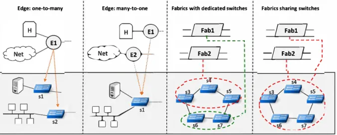
Regarding the virtual-to-physical mapping, we wish to leave as much freedom as possible for greater flexibility and also to be able to port a same edge-fabric virtual topology over multiple physical infrastructures. Figure 3 exposes a few virtual-to-physical mapping examples for both edges and fabrics. One virtual edge can map to one or more physical edge switches, and many virtual edges can map to the same physical switch. This allows the network operator to make a design choice (eg 1 edge vs 2 edges) independently of the target physical infrastructure. Sirnilarly, for fabrics, different mappings are possible on core physical switches: a dedicated set of switches for each fabric or sharing a subset of switches. The cost of this flexibility lies within AirNet's hypervisor (described in Section 6) that will implement the composition and mapping algorithms.
To recap, we believe that decomposing network policies, thanks to clear interfaces, into transport, control, and data functions will enable network operators to write control prograrns that are much easier to understand, reason about, and maintain. More importantly, the possibility to interconnect multiple edges, data machines, and fabrics provides a good level of abstraction going from a simple virtual topology with a single fabric (very similar to the abstraction level of the OBS mode]) to more
Network operator
�-
.
AirNet Languager---ï
':
I
l
1: . High-level Policies .:::::::::::::::::::::
•
input·---+ Virtual-to-Physical+
:
---
L
I
Virtual Network I 1 Mapping input , .... _______ __._ 1 .____
�___
....,�----
---·
AirNet Hypervisor Controller API Controller integration SON Controller Packet ln, statistics, topology events, etc.FIGURE 4 AirNet's architecture overview. SDN, software-defined networking
complex topologies involving several edges and fabrics. In addition, the Edge-Fabric model ensures sufficient flexibility to be able to consider both various high-level policies and contexts of use (eg, campus networks, data centers, operator networks), and existing physical constraints if necessary.
4 1 AIRNET OVERVIEW
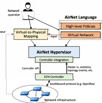
This section briefly presents AirNet's general architecture as well as its methodology. As shown in Figure 4, AirNet is composed of 2 main components: a high-level control language, that is completely built on the edge-fabric network abstraction model, and a hypervisor whose main goal is to support the virtual-to-physical mapping. These 2 parts will be detailed in Sections 5 and 6, respectively.
To specify and execute an AirNet program, 3 main phases must be performed:
l. The first phase deals with the design of the virtual network, in terms of virtual components ( edges and fabrics, hosts, and networks) and links between these components.
2. The second step consists in specifying the control policies that will be applied over the virtual network, namely, edge, transport, and data policies.
3. Finally, in the third phase, mappings existing between the virtual units and the switches present at the physical level have to be defined. Note that this last phase is separated from the first 2 allowing network operators to reuse their control program over different physical infrastructures without requiring any changes apart from the mapping instructions.
The result of these 3 phases is used as an input for the AirNet hypervisor that composes the virtual policies, compiles, and deploys them according to the target network infrastructure.
5 1 EDGE-FABRIC VIRTUAL NETWORK CONTROL LANGUAGE
In this section, we start presenting the language's key instructions and programrning pattern, then we show how to use them to specify 3 types of policies: starie control, dynarnic control, and data policies (with transport policies being included in each one of them). We illustrate their application through different small examples, all of which have been successfully tested in Section 8.
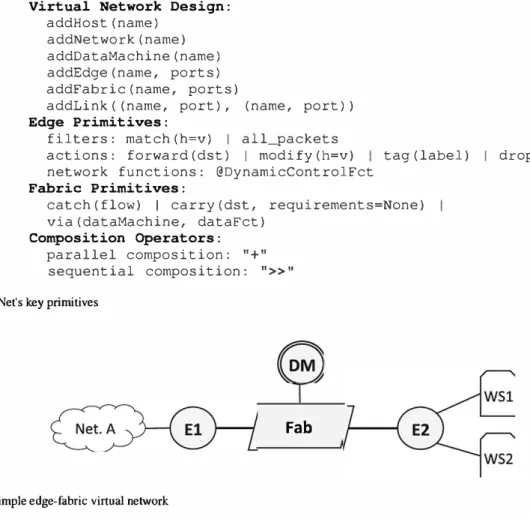
Virtual Network Design: addHost(name) addNetwork(name) addDataMachine(name) addEdge(name, ports) addFabric(name, ports)
addLink((name, port), (name, port)) Edge Primitives:
filters: match(h=v) 1 all_packets
actions: forward (dst) 1 modify (h=v) tag (label) 1 drop network functions: @DynamicControlFct
Fabric Primitives:
catch (flow) 1 carry (dst, requirements=None) via(dataMachine, dataFct)
Composition Operators:
parallel composition: "+"
sequential composition: ">>n FIGURE 5 AirNet's lœy primitives
FIGURE 6 A simple edge-fabric virtual network
5.1
1AirNet's key instructions
Fab
The virtual network and control policies are specified thanks to several AirNet's instructions summarized in Figure 5.
5.1.1
1Virtual network desi
gnDesigning the virtual network relies on a straightforward declarative approach: One primitive for each virtual unit that has to be added to the network ( addHos t, addEdge, etc). For each virtual component, the adrninistrator must specify the identifier and the number of ports it contains. Theo, in the second step, the adrninistrator must connect ail these devices using the addLink primitive, indicating which devices and ports are to be connected. A simple virtual network is shown in Figure 6. We will rely on this topology throughout this section to illustrate the different control policies.
5.1.2
1High-level policies
AirNet policies are divided into 2 main groups: edge policies and fabric policies. Both types are formed by composing the basic primitives listed in Figure 5 using parallel and sequential composition operators. These operators are similar to those found in related work such as the Pyretic language.17
The sequential composition operator (») applies a policy to the result returned by another policy that precedes it in the composition chain. Thus, Pl» P2 means that policy P2 will be applied to the result (set of packets) returned by policy Pl. On the contrary, the order of appearance of policies has no impact in the case of parallel composition. lndeed, the parallel composition operator ( +) gives the illusion that 2 or more actions are executed at the same rime on the same set of packets. Thus, Pl+ P2 means that both policies will be applied on the input packets but with no guarantee on the execution order.
By composing edge and fabric primitives, the network operator is able to specify 3 types of policies:
• Static control policies are policies that can be compiled and installed on the network proactively. They contain both edge and fabric policies.
• Dynamic control policies are executed at runtime by the control plane. They rely on network fonctions that cannot be implemented within the data plane (decision algorithm, maintaining state, etc). They can only be attached to edges.
• Data policies apply complex processing that cannot be performed by the basic set of actions (ie, forward, modify, drop). They are specified thanlcs to Data Machines and specific fabric policies.
The following subsections will explain in more depth these policies and illustrate them on small examples.
5.2 1 Static control policies
Starie control policies are evaluated and applied proactively on the target network. In other words, they do not depend on events that may occur at runtime. Static control policies follow a match-actions pattern on edges and a catch-carry pattern on fabrics. The match(h=v) primitive returns a set of packets that have a field h in their header matching the value v. Actions are then applied on the sets of packets returned by the match. Drop, forward, and modify are standard actions found in most network control languages. As for the tag action, it attaches a label onto incoming packets, label that is used by fabrics to identify and process a packet. The catch primitive captures an incoming flow on one of the fabric's ports, and the carry primitive transports a flow from one edge to the other (both connected to the fabric). It is also possible to specify in the carry primitive forwarding requirements such as maximum delay to guarantee or minimum bandwidth to offer.
As a simple example, we consider Figure 6's virtual network that has to be configured to allow flows from Net . A to host
WSl. To meet this objective, 2 edge policies and l fabric policy must be defined:
el match(edge="El", src="Net.A", dst="WSl") >> tag("in wsl") >> forward("Fab") tl = catch(fabric="Fab", src="El", flow="in wsl") >> carry(dst="E2")
e2 = match(edge="E2", dst="WSl") >> forward("WSl")
Policy el uses the match instruction to capture all flows coming from Net .A and having WSl as destination, then it tags these flows as in_ ws 1 by sequentially combining the match with a tag instruction. The result is passed to the forward action that transfers the packets to the output port leading to the Fab fabric. In the transport policy tl, ail flows labeled in_ wsl are carried from edge El to edge E2. Finally, policy e2 matches packets according to their destination and forwards them to the appropriate host.
5.3 1 Dynamic control policies
As we have just seen, filters and actions allow network operators to write simple and static control policies. However, we believe that a control language should provide more powerful instructions to allow operators to write sophisticated and realistic control applications that can meet a variety of requirements. To folfill this goal, we have integrated the concept of dynarnic control fonction that implements a decision-making process capable of generating, at runtime, new policies that change the control program's behavior.
Dynarnic control fonctions are defined in AirNet by using a decorator design pattern over user-defined fonctions. Programmers will thus be able to transform their own (or imported) fonctions by simply applying a specific decorator. Once this decorator is applied, the resulting fonction can be composed with other AirNet primitives, thereby building advanced policies.
@DynamicControlFct(data="packet", limit=number, split=[h=v]) @DynamicControlFct(data="stat", every=seconds, split=[h=v))
As shown in the above syntax, the DynamicControlFct decorator has a data parameter that specifies whether to retrieve entire network packets or statistics related to the number of received bytes and packets. If network packets are used, then the limit and split parameters apply. The limit defines how many packets (from the matched flow) must be redirected to the network fonction. If limit is set to None, it means that all packets need to be redirected to the network fonction. The second parameter is split, allowing to discriminate between packets that are sent to the network fonction. The split parameter is a list of headers (eg, split= [ "nw_src", "tp_dst"]) that is used as a key to identify subflows on which the limit parameter applies. If split is
set to None, it means that the limit parameter applies on the entire flow. If statistics are used instead of entire network packets, limit is replaced by a polling period specified thanks to the every parameter.
5.3.1
1Load balancer example
As a concrete example, we will consider a use case that implements a dynarnic load balancer on the previous virtual topology ( cf. Figure 6). The load balancing fonction is installed on edge E2. The e2 l policy displayed below intercepts web flows (ie, HTTP flows sent to the web server's public address) and passes them to a dynarnic control fonction (Dynamic_LB) that generates a new policy changing the destination addresses of these flows to one of the backend severs (ie, WSl and WS2), while ensuring a
workload distribution over the 2 servers. The edge E2 needs also to modify the servers responses to restore the public address instead of the private ones (eg, policy e22 for the private host WSl)).
e21 match (edge= "E2", nw dst=PUB WS IP, tp_dst=HTTP) >> Dynamic_LB () e22 = match(edge="E2", src="WSl")
->> modify(nw src=PUB WS IP) ->> modify(dl src=PUB WS MAC)
>> tag("out_web_flows")->> forward("Fab")
-As shown below, the Dynamic _ LB fonction is triggered for each first packet coming from a different 1P source address, since the parameter limit is set to "l", and the pararneter split is set to "nw_src". The fonction extracts the match filter from the received packet then uses it to generate a new policy for the other packets that belong to the same flow as the retrieved packet. Hence, one new forwarding rule will be installed at runtime on the physical infrastructure for each flow with a different 1P source address. Regarding the forwarding decision, it is based on a simple round-robin algorithm: If the value of a token is one, then the flow is sent to the first backend server, else it is sent to the second one.
@DynamicControlFct(data="packet", limit=l, split=["nw_src")) def Dynamic LB(self, packet):
if self.rrlb token == 1:
self.rrlb token = 2
return (my match >> modify(nw dst="WSl IP") >> modify(dl_dst="WSl_MAC")
>> forward ( "WSl") ) -
-else:
self.rrlb token = 1
return (my match >> modify(nw dst="WS2 IP") >> modify(dl_dst="WS2_MAC")
>> forward ( "WS2") ) -
-5.3.2
1Data cap example
As explained previously, dynarnic control fonctions can also rely on network statistics. Here, we present a data cap use case that monitors and possibly suspends traffic coming from a particular host if it exceeds a data threshold (again, we use the virtual topology shown in Figure 6):
match(edge="El", src="Net.A") >> tag("in flows") >> ( forward("Fab") + check_data_cap() )
The check_data_cap fonction is executed in parallel of the forward action (thanks to the+ operator). Based on the decorator's arguments, the fonction is called by the network hypervisor every hour, providing statistics sorted by network source address. If the number of bytes exceeds, the threshold then a new drop policy is returned for that flow:
@DynamicControlFct(data="stat", every=3600, split=["nw src"))
def check data cap(stat):
-if stat�byte=count > threshold: return (stat.match >> drop)
Note that policies returned by dynarnic control fonctions are always installed with a higher priority than existing ones. In this example, it guarantees that the drop action on the subflow is installed with a higher priority than the global forward action executed in parallel, thus only blocking the flows that exceed the threshold.
5.4 1 Data policies
Until now, we have seen that AirNet allows to easily configure paths and other control fonctions within a virtual network, configuration which may be static or dynarnic. However, it is quite common, especially today with the rise of network fonctions virtualization (NVF), to have networks that include several network appliances or middleboxes that implement complex data processing on the packet's payload that cannot be performed by the switches' basic set of actions (ie, forward, modify, drop). Encryption, compression, or transcoding are examples of such fonctions. For this purpose, AirNet provides a mechanism to easily redirect a flow through one or several data plane middleboxes that we define as DataMachines. Sirnilarly to edges, a DataMachine must be connected to a fabric. However, they are not associated to any AirNet primitive since their processing depends only on the data fonction hosted by the target middlebox existing in the network infrastructure.
As an example of such policies, we consider several clients strearning media from a Video on Demand (VoD) service hosted on host WSl (again relying on Figure's 6 virtual topology). We assume that flows from the VoD service consumed by Net .A end-users must pass through the codec conversion fonction deployed on the DM data machine. This policy can be completely specified within the fabric that implements the service chaining logic between the virtual units thanks to the via primitive:
tl catch(fabric="Fab", src="E2", flow="out vod flows") >> via(dataMachine="CC", dataFct="CodecConversion") >> carry(dst="El")
6 1 AIRNET'S HYPERVISOR
6.1
1Overview
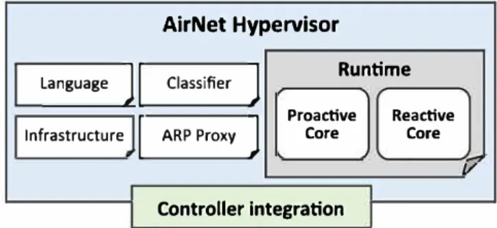
The AirNet language has been implemented as a domain-specific language embedded in Python, as well as a runtime system that we name "AirNet hypervisor." Figure 7 gives an overview of the different modules included in the hypervisor.
To ensure the composition of AirNet's virtual policies as well as their mapping on the physical infrastructure, the hypervisor relies on 6 modules:
• Language: contains classes and data structures that implement the primitives and operators of the AirNet language.
• Classifier: implements the logical structures that store control mies according to their priority and that solve match intersection issues between policies.
• Runtime: hypervisor's core module that implements, in particular, the composition and mapping algorithms. The next section focuses on this module.
• Infrastructure: centralizes ail information regarding the network infrastructure and maintains a global, coherent, and up-to-date view of the physical topology.
• ARP proxy: deals with issues related to the ARP protocol.
• Controller integration: allows the hypervisor to communicate with existing SDN controllers (the current version supports POX4 and Ryu5 controllers). This module is the only component to update if we were to port the hypervisor on a new SDN controller.
6.2
1Runtime module
The runtime module is the centerpiece of AirNet's hypervisor, as it is at this level that virtual policies are transformed into phys ical mies. The runtime module talœs input from the other modules of the hypervisor (infrastructure, language, and classifier), applies the compilation algorithms, and then generates a set of physical mies for the data plane devices. These mies are then passed to the controller integration module to be transformed into OpenFlow mies and installed on the physical switches.
The mntime module includes 2 major parts that support the execution of the two main operating modes of an AirNet program, proactive mode, and reactive mode:
• The proactive core installs starie policies on the data plane.
• The reactive core addresses issues related to the execution of dynamic control fonctions and changes that may occur in the physical topology (eg, link down).
In the following, we present briefly the functionalities of each of these 2 cores, a more detailed description as well as the algorithms they implement is available in Aouadj.11
Language
j
InfrastructureFIGURE 7 AirNet's hypervisor overview
1
1
AirNet Hypervisor
Classifier
j
Runtimej
Proactive ReactiveARP Proxy Core Core
j/
6.2.1
1Proactive core
It is composed of 2 main phases:
• Virtual composition: The policies are composed together to solve intersection issues.
• Physical mapping: High-level policies are transformed into low-level physical rules.
Virtual composition is completely independent of the physical infrastructure. It essentially uses the fonctions defined in the language and classifier modules to transform the control policies into a set of intermediate rules and store them by order of priority in logical containers called classifiers.
The second phase consists in compiling the rules stored in the classifier, depending on the target physical infrastructure and on the mapping instructions that have been defined by the adrninistrator.
For each edge rule, the proactive core retrieves the physical switches associated with that edge and then transforms the rule into one or more physical rules. This transformation includes, for example, the replacement of symbolic identifiers by low-level physical parameters (network addresses, output port, etc).
As for fabric rules, it is not a trivial algorithm since we cannot just rely on the fabric's forwarding table to install flow rules, mainly because an edge can map to more than one physical switch, and hosts that are connected to this edge can be in reality connected to different physical switches. Thus, we need to split flows that are carried to an egress edge into several flows according to the final destination. In other words, we only deliver (following a shortest path algorithrn) to border switches the flows that are intended for a destination directly connected to that switch, and not all the flows arriving to the virtual egress edge.
6.2.2
1Reactive core
The reactive core manages a11 interactions with the physical infrastructure during runtime. It performs 2 main fonctions: man aging the life cycle of dynarnic network fonctions and adapting control rules to physical infrastructure changes. We can divide the life cycle of a network fonction within the controller into 3 main phases that can be surnmarized as follows:
• lnitialization: The reactive core installs data path rules responsible for sending packets and statistics to the controller, and it creates data structures named buckets that will receive and process this data at runtirne.
• Processing incoming packets: Each time a packet or a statistic is forwarded to the hypervisor, the reactive core looks up the appropriate fonction to apply. Once the dynarnic control fonction is executed, the new returned policy is compiled and enforced on the physical infrastructure.
• Limit reached: When a flow lirnit is reached, the reactive core deletes the data path rule responsible for the redirection of packets (or statistics) to the hypervisor.
The second feature of the reactive core deals with changes that may occur at the physical infrastructure level such as the discovery of a new path or the disconnection of a link. As soon as a topology event is received by the hypervisor, the reactive core of the runtirne module activates a procedure to adapt to this new infrastructure. This procedure contains 3 main steps: (l) recalculate paths by executing the physical mapping phase to generate new classifiers that are consistent with the new infrastructure; (2) generate dictionaries of differences between the old and the new classifiers, containing rules to be added, deleted, or modified on each physical switch; and (3) enforce the updates on the physical infrastructure by generating the corresponding OpenFlow rules.
7 1 USE CASE
In this section, we present a complete use case, which consists in configuring an enterprise network that offers authentication and load balancing network services. The goal is to show how a realistic AirNet program is built and executed from start to end. As a proof of concept, the use case has been irnplemented and tested on the Mininet network emulator.29
We suppose that the entreprise's network includes 2 subnets: one for internal users (employees) and one for external users (guests). Moreover, 4 servers are hosted within the enterprise: 2 web servers and 2 database servers. The following requirements are defined:
• The web servers must be accessible to a11 internai and external users.
• The database servers are only accessible to employees of the company who have an authorization. These employees must be located on the internal users network.
FIGURE 8 Virtual topology for the use case PAuth PFabric Fabl PFabric Fab2
• A Joad balancing policy should be installed for the private web and database servers.
In the following, we present the 3 steps that need to be performed for any AirNet program, namely, the design of the virtual topology, the specification of the control policies, and finally the virtual-to-physical mapping mies.
7 .1
1Designing the virtual topology
This step is ail about design choices (eg, number of edges and fabrics) that are guided primarily by the control policies to implement or by constraints that may exist in the physical infrastructure.
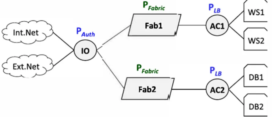
In the context of this use case, we have opted for the virtual topology illustrated in Figure 8. Within this virtual topology, the edge IO acts as a host-network interface between the users and the network. We chose to use a single edge as an entry point to the entreprise network to group all the access control policies in a single virtual component. We used 2 distribution edges ACl
and AC2 to connect the private servers of the company to the network to install a Joad balancing policy on each edge. Finally, the virtual topology includes 2 fabrics (FABl and FAB2). The purpose of this design choice is to conceptually distinguish 2 transport paths depending on the final destination (we could have made another design choice and use only one fabric).
7 .2
1Specifying the control policies
Considering both the virtual topology we have just presented and the high-level objectives of this use case, we need to define the following policies:
• Input/output policies for forwarding packets to and from internai and external users. These policies will include starie for warding policies as well as a dynarnic authentication policy to control access to the database servers. They will be naturally installed on edge IO, the input of the network.
• Load balancing policies between the private servers of the entreprise. They include 2 dynarnic control functions: one for the web servers installed on ACl and one for database servers installed on AC2.
• Transport policies to configure the 2 fabrics of the network.
7.2.1
1Input/Output policy
As shown below, a unique function can be defined to group ail policies included in edge IO: def IO_policy():
il = match(edge=IO, nw dst=PUBLIC WS IP, tp dst=HTTP) >> tag(in web flows)
>> forward(FABl) - - -
-i2 = match(edge=IO, src=IntNet, nw dst=PUBLIC DB IP) >> authenticate() i3 = match(edge=IO, dst=IntNet) >>-forward(IntNet)
i4 = match(edge=IO, dst=ExtNet) >> forward(ExtNet) return il + i2 + i3 + i4
This function includes 4 policies: 3 static and 1 dynarnic policy. The first policy (il) tags ail web packets to the web server's public 1P address and forwards them to fabric FABl. Policies i3 and i4 are standard distribution policies that forward packets to
internai and external users of the network, respectively. Finally, policy i2 captures ail packets from the internai users network that have the database server's public 1P address as a destination and sends them to the dynamic authenticate fonction.
These 4 policies are composed together (using the parallel operator) to form a global access control policy that will be installed on edge IO.
The program below represents the AirNet code for the authentication fonction. For the sake of sirnplicity, this dynamic fonction is based on the packet's 1P source address and on a whitelist of authorized hosts. The fonction's decorator subscribes to every first packet (limit=l) of each new source (spli t= [ "nw _src"] ). According to that packet, the fonction will return a new policy either forwarding the flow to fabric Fab2 or dropping traffic from that flow.
@DynamicControlFct(data="packet", limit=l, split=["nw src"])
def authenticate(packet):
-ip = packet.find('-ipv4')
host_ip_src = ip.srcip.toStr()
if host ip src in whitelist:
new�oiicy (match(edge=IO, nw src=host ip src, nw dst=PUBLIC DB IP) else:
new_policy
return new_policy
7 .2.2
1
Load balancing poli
cy>> tag(in_trusted_flows)->>-forward(FAB2))
-(match(edge=IO, nw_src=host_ip_src, nw dst=PUBLIC_DB_IP) >> drop)
As for edge IO, a dynamic control policy must be installed on edges ACl and AC2 to forward packets to AirNet's hypervisor
that executes the load balancing fonction. We will not expose this fonction since it is very sirnilar to the one presented in Section 5.3.1. The only difference is that we add to the fonction an argument that contains addressing information related to the private
servers on which the load balancer operates. This allows us to reuse the same fonction on both edges AC2 and AC2.
7 .2.3
1
Transport poli
cyThe last policies define the transport policies to be installed on both fabrics. Specifically, this involves specifying catch-carry rules for each label that has been previously inserted by the different edges. In this use case, the transport policies are trivial as shown in the program excerpt below.
def fabric_policies():
tl catch(fabric=FABl, src=IO, flow=in web flows) >> carry(dst=ACl) t2 = catch(fabric=FABl, src=ACl, flow=out web flows) >> carry(dst=IO)
t3 = catch(fabric=FAB2, src=IO, flow=in trusted flows) >> carry(dst=AC2) t4 = catch(fabric=FAB2, src=AC2, flow=out_trusted_flows) >> carry(dst=IO) return tl + t2 + t3 + t4
7.3 1 Defining the mapping module
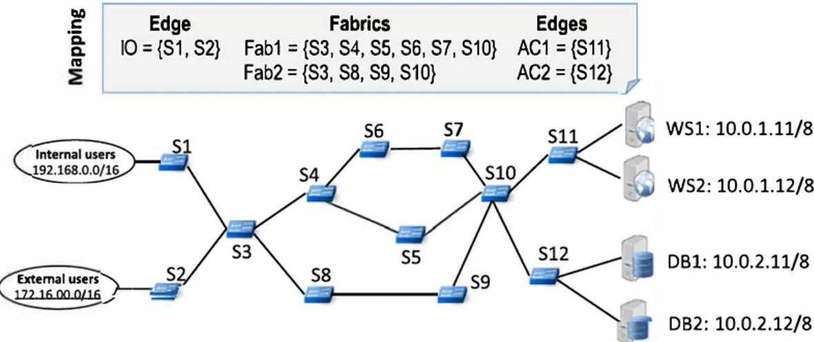
For this use case, we relied on the physical infrastructure depicted in Figure 9. Among the 12 OpenFlow switches, 4 are edge switches and 8 are core network switches. The mapping ru les are also shown in this figure. The edges of the virtual topology are necessarily associated with edge physical switches. Here, we used 2 different mapping strategies: (1) one-to-one for the edges
ACl and AC2 and (2) one-to-many for the edge IO. Concerning the fabrics, we chose a mapping that differentiates 2 different
physical paths: s3, s4, s5, s6, s7, s10 for fabric Fabl and s3, s8, s9, s10 for fabric Fab2.
7 .4 1 Execution results
This use case has been implernented and tested on the Mininet network emulator. In the first phase, the AirNet hypervisor compiles the high-level policies and generates OpenFlow rules that are pushed onto the switches through the SDN controller. On top of static forwarding rules installed on the different switches, OpenFlow entries that send packets to the controller are installed on the physical edges, due to the authentication and load balancing dynamic control fonctions.
Next, at runtime, we executed several web requests on the web server from hosts connected to s1 and s2. All the requests and their responses were correctly routed through the network and processed by either WSl or WS2, allowing the web clients to
tlO C ïi 0. n,
Edge
10 = {S1, S2} Extemal users 172.16.00.0/16 ;--�--Fabrics
Fab1 = {S3, S4, S5, S6, S7, S10} Fab2 = {S3, S8, S9, S10} S6 S7FIGURE 9 Enterprise physical infrastruc ture and associa te d mapping rules
Edges
AC1 ={S11} AC2 = {S12}TABLE2 Number of virtual polic i es and physical rules for the use case
Virtual device 10 Fabric 1 et2
Policies 4 4
Physical switch sl s2 s3 s4 s5 s6 s7 s8 s9 slO
R11les (init. phase) 5 5 5 4 4 2 2 5
R11les (link s4/s5 down) mo d l -3 +3 +3 mod2
R11les (lmHost to WS) +l +l +l +l
R11les (lmHost to DB) +l +l +l +l +l +l
Note:-, no change in the number of rules; Bold, to underline important information
WSl: 10.0.1.11/8 WS2: 10.0.1.12/8 DBl: 10.0.2.11/8 D82: 10.0.2.12/8
ACl AC2 Total
3 3 14 sll sl2 Total 5 5 44 47 +l 49 +l 55
retrieve the requested HTML files. We also tested traffic to the database servers where only whitelisted hosts could access the servers, while flows from other hosts were dropped at the border of the network.
Table 2 summarizes the number of rules obtained for each switch and each test phase. These figures clearly highlight the significant difference between the number of policies specified by the administrator and the number of rules actually installed by the hypervisor. For a single user (ie, a single source flow ), a factor of 3 exists between the number of policies and the number of OpenFlow rules for the proactive phase and a factor of 4 for the reactive phase (access to database servers). This number of course increases linearly as a fonction of the number of different source flows for the dynarnic control fonction.
Lastly, we tested link failures by manually shutting down ports between s4 and s5. Link down events were received by the reactive core that recompiled the Fabl fabric, found a new path (via s6 and s7) and then reconfigured the OpenFlow switches to use this new path.
8 1 EXPERIMENTAL RESULTS
In this section, we present sorne experimental results we have obtained by conducting fonctional, performance, and scalability tests. In the first set of tests (Table 3), we executed 5 use cases addressing different scenarios with different virtual topologies (detailed in Section 5). These tests were perforrned on the same physical topology composed of 11 physical switches. In the
TABLE3 Number of polic i es and rules for each use case
Virtual Physical Composition Physical
Use case policies rules generated time,ms mapping time, ms
twoFab 12 42 101 20
dynllJ 9 31 94 16
bwCap 6 27 89 11
dataFct (comrol plane) 6 25 95 14
s. ... UH CAM wlth dttt.ffnt phy•lc.a topologl••
2S0+----4al -Vlrtu.lilco�stlontrm• l'hyslcal ffllpf)lng Cima -JO'J Và'tul'hysl�I INoppl'lg tlma �«imposltlontlma
f---200+-------1
6 policics 11 policics 20 poki� 29 poli<ics 38 pollcies 7 SW 1$ SW 31 SW 63 SW 127 SW
(31 rules} (45 rvtes) (9'9 rules} (183 rules) (347 nAes)
Delay ffopology wlth 11 physkal swttçhes)
,
...
....,..--...-... .._-
-• -...
No netwofti: function_
....
__
...,
-•-Oatafunctiol'l_dataplwie
••-' r-11--+--+--+---·•..;.0:.,..ynamlc conl.TOI function
' ' ' •ot-t--,., -+---+-+--+--+---+--+---t-1
!
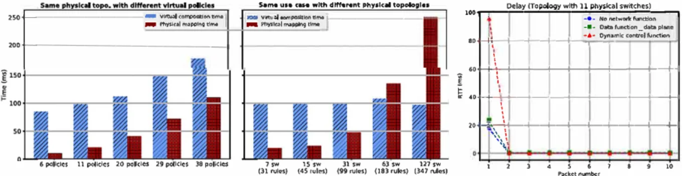
i � 40�-<....+--+-+---+--+---+-+--+-0 _, . ' ' ' ··--�· l--+--+--+-+----+---1--1-1 '�', \�1 1 2 3 4 S 6 7 8 9 10 Packet nurnberFIGURE 10 Compilation time according to the number of virtual policies (left) and to the number of physical switches/rules (center). Impact of dy namic control and data functions on the round-trip time (right)
second set of tests (Figure 10 left and center), we did some measures with greater number of virtual policies as well as larger physical topologies. Finally, the last set of tests (Figure 10 right) concentrated on end-to-end delay with respect to dynarnic network fonctions utilization. AU these tests were performed with Mininet in a virtual machine with 2 GB of RAM and a 2,7 GHz Intel Core i5 CPU.
Table 3 shows the execution results in terms of total physical rules generated and compilation time divided into 2 steps: (l) the virtual composition step that mainly includes retrieving infrastructure information to build a corresponding graph and composing virtual policies to resolve all intersection issues, (2) the physical mapping step that includes transforrning virtual policies into physical rules, finding appropriate paths for each flow, and finally distributing physical rules on switches according to the specified mapping module.
Number of generated physical rules. Table 3 underlines the differences between the number of specified virtual policies and the number of rules actually installed by our hypervisor on the physical switches, which is greater by a factor 2 or 3. Thus, a first conclusion that we can draw is that the usage of AirNet effectively simplifies network programmability, and this not only by providing modern control instructions but also by sparing adrninistrators from the tedious task of writing a large number of low-level rules and handling at the same time their intersection and priority issues. Moreover, the cost of this simplification is highly acceptable since, for ail the use cases, it remains in the order of a hundred rnilliseconds.
Virtual composition time. As illustrated in Figure 10, the virtual composition time is highly correlated to the number and the complexity of the specified virtual policies, but totally independent from the size of the physical infrastructure. lndeed, we can see on the left graph that the more virtual policies, the greater the virtual composition time is. However, on the center graph, the same control program executed over different physical topologies (varying from 7 to 127 switches) shows the same virtual composition time.
Physical mapping time. Still looking at Figure 10, we can see that the physical mapping time is correlated to both virtual policies and physical infrastructure. On the left graph, we have the same physical topology, but the more virtual policies are added, the more the hypervisor needs to solve policy composition issues, which ultimately gives a greater mapping time. The same goes for the center graph, the number of policies does not change but the more the topology is large and complex, the more the hypervisor needs to perform calculation to find paths and install a large number of physical rules, thereby resulting in a greater physical mapping time.
Dynamic and data fonctions delay. We finally made tests to measure the impact of dynarnic control and data fonctions on the end-to-end delay. To conduct this experiment, we installed a path between 2 hosts within the network (composed of 11 physical switches) and measured the round-trip time between them using 3 different approaches: (l) the path is installed proactively (ie, at deployment time) and does not pass through any dynarnic control fonction nor data machine; (2) the path is installed proactively but goes through a data machine; and (3) the path is installed reactively following the execution, at runtime, of a dynarnic control fonction. The right graph of Figure 10 shows the results.
With no network fonction, the first measure is higher than the other 9: this is due to the initial ARP query that is handled by our proxy within the controller (in fact, this ARP delay is present in the 3 approaches).
For data fonction tests, we used the Click software router> as a data machine and a simple redirection fonction that receives a packet on an input interface and redirects it to an output interface without complex processing on the packet itself. The particularity of this type of path is that the data fonction is applied on ail packets of the flow and not only on the first one. This normally implies a greater impact on end-to-end delays. However, this delay depends essentially on the data fonction's processing and not on the AirNet hypervisor. This is confirmed by our measures that show a plot very sirnilar to the previous test with no network fonction.
1
Finally, regarding the dynarnic control fonction, the higher delay is on the first packet
<�
95ms). This is mainly due to the rime required to redirect the first packet of the flow to AirNet's hypervisor, to evaluate the fonction and install the new end-to-end path according to the returned policy. Once the new path is installed, the round-trip rime is equivalent to the one of proactive starie paths.9 1 CONCLUSION
This paper described the design and the implementation of AirNet, a new high-level domain specific language for prograrnming virtual networks. The originality of the AirNet language lies in the fact that it is based on the Edge-Fabric abstraction model. This feature allows AirNet to make a clear distinction between transport policies and more complex network services. AirNet has a prograrnming mode] that consists in first specifying a virtual topology that corresponds to high-level design needs or existing physical constraints, and then specifying the control policies that will run over that virtual topology. These policies are divided into 4 main types: transport policies, static control policies, dynarnic control policies, and data policies.
An implementation of the AirNet language was also conducted. This prototype includes in particular a library of AirNet's primitives and operators, as well as a hypervisor that ensures the composition of control policies and their mapping onto the physical infrastructure. To rely on existing SDN controllers, the hypervisor includes integration modules for the POX and RYU controllers. Experimental validation was performed on different use cases (fùtering, Joad distribution, dynarnic authentication, bandwidth limitation, etc), the results of which demonstrate the feasibility of our solution. Finally, performance measurements have shown that the extra cost of this new layer of abstraction is perfectly acceptable.
Currently, we are testing the AirNet hypervisor on larger-scale use cases and finishing some implementation issues. Also, we are working, on the one hand, on runtime verification techniques to check that the installed physical rules are consistent with the operator's virtual control policies and, on the other band, on the possibility to integrate AirNet within an NVF architecture, where data machines will correspond to VNFs (virtual network fonctions).
ORCID
Emmanuel LavinatG http://orcid.org/0000-0002-5899-0444
REFERENCES
1. Benson T, Akella A, Ma!tz D. Unraveling the Complexity of Network Management. In: Proceedings of the 6th USENIX Symposium on Networlœd Systems Design and lmplementation, Boston, Massachusetts; 2009:335-348.
2. Raghavan B, Casado M, Koponen T, Ratnasamy S, Ghodsi A, Shenker S. Software-defined Internet Architecture: Decoupling Architecture from Infrastructure. In: Proceedings of the 11th ACM Workshop on Hot Topics in Networks ACM, Redmond, Washington; 2012:43-48.
3. Ghodsi A, Shenker S, Koponen T, Singla A, Raghavan B, Wilcox J. Intelligent Design Enables Architectural Evolution. In: Proceedings of the
10th ACM Workshop on Hot Topics in Networks ACM, Cambridge, Massachusetts; 2011:3:1-3:6.
4. The POX controller. Online: http://www.noxrepo.org/pox/about-pox/. Accessed: March 13, 2015.
5. Nippon Telegraph and Telephone Corporation. RYU network operating system. URL http://osrg.github.com/ryu/ 2012. Last access: January 2017.
6. Berde P, Gerola M, Hart J, et al. ONOS: Towards an Open, Distributed SDN OS. Proceedings of the Third Workshop on Hot Topics in Software Defined Networking, HotSDN '14. New York, NY, USA: ACM; 2014:1-10.
7. Erickson D. The beacon openflow controller. In: Proc. of the Second ACM SIGCOMM Workshop on HotTopics in Software Defined Networking (HotSDN'13) ACM, Hong Kong, China; 2013:13-18.
8. Chowdhury NMK, Boutaba R. Network virtualization: state of the art and research challenges. IEEE Commun Mag. 2009;47(7):20-26.
9. Chowdhury NMK, Boutaba R. A survey of network virtualization. Comput Networks. 2010;54(5):862-876.
JO. Aouadj M, Lavina! E, Desprats T, Sibilla M. Towards a virtualization-based control Janguage for SDN platforms. In: Proc. of the 10th lot. Conf. on Network and Service Management (CNSM), Rio de Janeiro, Brazil; 2014:324-327.
I 1. Aouadj M, Lavina! E, Desprats T, Sibilla M. Composing data and control fonctions to ease virtual networks programmability. NOMS 2016
-2016 IEEF/IFIP Network Oper Manage Symp. 2016:461-467.
12. Hinrichs TL, Gude NS, Casado M, Mitchell JC, Shenker S. Practical declarative network management. In: Proc. of the 1st ACM Workshop on
Research on Enterprise Networking ACM, Barcelona, Spain; 2009;1-JO.
13. Voellrny A, Agarwal A, Hudak P. Nettie: Functional Reactive Programrning for OpenFJow Networks. Technical Report YALEU/DCS/RR-1431, Yale University; 2010.
14. Foster N, Harrison R, Freedman MJ, Monsanto C, Rexford J, Story A, Walker D. Frenetic: A network programrning Janguage. S/GPLAN Notices.
15. Voellmy A, Kim H, Feamster N. Procera: A language for high-level reactive network control. In: Proc. HotSDN ACM, Helsinki, Finland; 2012:43-48.
16. Monsanto C, Foster N, Harrison R, Walker D. A compiler and run-time system for network programming languages. S/GPLAN Notices.
2012;471:217-230.
17. Monsanto C, Reich J, Foster N, Rexford J, Walker D. Composing Software Defined Networks. In: USENIX Symposium, NSDI, Lombard, IL; 2013:1-14.
18. Gutz S, Story A, Schlesinger C, Foster N. Splenclid isolation: A slice abstraction for software-defined networks. In: Proc. HotSDN Workshop ACM, Helsinki, Finland; 2012:79-84.
I 9. Soulé R, Basu S, Maran di PJ, et al. Merlin: A Language for Provisioning Network Resources. In: CoNEXT I 4. Sydney, Australia; 20I4:213-226.
20. Reitblatt M, Canini M, Guha A, Foster N. FatTire: Declarative Fault Tolerance for Software-defined Networks. In: Proœedings of the Second ACM SIGCOMM Workshop on Hot Topics in Software Defined Networking. Hong Kong, China: ACM; 2013: 109-I 14.
21. Voellmy A, WangJ, Yang YR, Ford B, Hudak P. Maple: Sirnplifying SDN programming using algorithmic policies. ACM S/GCOMM Computer
Communication Review. 2013;43(4):87-98.
22. Anderson CJ, Foster N, Guha A, et al. NetKAT: Semantic foundations for networks. ACM S/GPLAN Notices -POPL '14. 2014;49(1):I 13-126.
23. McKeown N, Anderson T, Balakrishnan H, et al. Openflow: Enabling innovation in campus networks. ACM S/GCOMM Computer Communica
tion Review. 2008;38(2):69-7 4.
24. Jain R, Paul S. Network virtualization and software defined networking for cloud computing: a survey. !EEE Comm11nMag.2013;51(11):24-31. 25. Casado M, Koponen T, Ramanathan R, Shenker S. Virtualizing the network forwarding plane. In: Proc. of the Workshop on Programmable
Roulers for Extensible Services of Tomorrow (PRESTO' 10), Philadelphia, Pennsylvania: ACM; 2010:8: 1-8:6.
26. Keller E, Rexford J. The ''Platform As a Service" Mode! for Networking. In: Proc. of the 2010 Internet Network Management Workshop (INM/WREN'lO) USENIX Association, San Jose, CA; 2010:4-4.
27. Ghein LD. MPLS Fundamentals. 1st ed. Indianapolis, IN 46240 USA: Cisco Press; 2006.
28. Casado M, Koponen T, Shenker S, Tootoonchian A. Fabric: A Retrospective on Evolving SDN. In: Proc. of the First Workshop on Hot Topics in Software Defined Networks (HotSDN'I2), Helsinki, Finland: ACM; 2012:85-90.
29. Mininet Overview. URL http://rnininetorg/overview/ Last access January 2017; 2010.
30. Kohler E, Morris R, Chen B, Jannotti J, Kaashoek MF. The Click modular router. ACM Trans Comput Syst. 2000;18(3):263-297.
Michelle Sibilla is a professor at University of Toulouse, France. She received her PhD degree in computer science from
Paul Sabatier University in 1992. She is deputy director of the Toulouse Institute of Computer Science R esearch (IRIT). Her main research interest is on integrated and autonomous management of networks and systems.
Messaoud Aouadj is a postdoctoral researcher at the University of Technology of Troyes in France. He received bis PhD degree in computer science from the University of Toulouse in 2016. His main research interests are network and service management with a focus on new network architectures such as soft.ware-defined networking, network fonction virtualization, and information-centric networking.
Emmanuel La vinai received bis Master of Science (2002) and PhD (2006) degrees in Computer Science from University of Toulouse, France. After bis PhD, he obtained a post-doc position at TELECOM ParisTech and then atINP-ENSEEIHT School of Engineering. Since September 2009 , he is an associate professor at University of Toulouse and a member of the IRIT research institute. His research interests include network and service management ( monitoring, dynarnic reconfiguration), software-defined networking, and network virtualization.
Thierry Desprats is an associate professor at University of Toulouse, France. He received bis PhD degree in computer science from Paul Sabatier University in 1993. He is a member of the IRIT research institute in Toulouse. His main research interests are network and service management as well as rniddleware for loT-based context-aware applications. He also teaches network and distributed systems in the Computer Science Department of University of Toulouse.
How to cite this article: Aouadj M, Lavinal E, Desprats T, Sibilla M. AirNet: An Edge-Fabric abstraction mode} to manage software-defined networks. /nt J Network Mgmt. 2017;27:el983. https://doi.org/10.1002/nem.1983