Any correspondence concerning this service should be sent
to the repository administrator:
[email protected]
This is an author’s version published in:
http://oatao.univ-toulouse.fr/226513
Official URL
DOI :
https://doi.org/10.4204/EPTCS.219.2
Open Archive Toulouse Archive OuverteOATAO is an open access repository that collects the work of Toulouse
researchers and makes it freely available over the web where possible
To cite this version:
Garoche, Pierre-Loïc and Kahsai, Temesghen and
Thirioux, Xavier Hierarchical State Machines as Modular Horn Clauses.
(2016) In: 3rd Workshop on Horn Clauses for Verification and Synthesis
(HCVS 2016), 3 April 2016 (Eindhoven, Netherlands).
doi:10.4204/EPTCS.219.2
Hierarchical State Machines as Modular Horn Clauses
∗Pierre-Loïc Garoche
DTIM, UFT, Onera – The French Aerospace Lab
Temesghen Kahsai
NASA Ames / CMU
Xavier Thirioux
IRIT/ENSEEIHT, UFT, CNRS
In model based development, embedded systems are modeled using a mix of dataflow formalism, that capture the flow of computation, and hierarchical state machines, that capture the modal beahviour of the system. For safety analysis, existing approaches rely on a compilation scheme that transform the original model (dataflow and state machines) into a pure dataflow formalism. Such compilation often result in loss of important structural information that capture the modal behaviour of the system. In previous work we have developed a compilation technique from a dataflow formalism into modular Horn clauses. In this paper, we present a novel technique that faithfully compile hierarchical state machines into modular Horn clauses. Our compilation technique preserves the structural and modal behavior of the system, making the safety analysis of such models more tractable.
1
Introduction
Model-based development is a leading technique in developing software for critical embedded systems such as automotive, avionics systems, train controllers and medical devices. Typically such systems are modeled using a mix of dataflow formalism and hierarchical state machines. For instance, Matlab Simulink [20] or Esterel SCADE [9] diagrams are typically used to specify aspects of a system that can be modeled by differential equations relating inputs and outputs (i.e., dataflow), while Matlab State-flow [21] charts or Esterel SCADE automata usually model the control aspects. The extensive use of the aforementioned formalism in the development of safety-critical systems, associated with certification standards [8] that recommend the use of formal methods for the specification, design, development and verification of software, makes a formal treatment of these notations extremely crucial.
For the purpose of safety analysis, Simulink/SCADE models are compiled to a lower level modeling language, usually a synchronous dataflow language such as Lustre [5]. Preserving the original (hierar-chical and modular) structure of the model is paramount to the success of the analysis process. In [10] we have illustrated a technique to preserve such structure via a modular compilation process. Specif-ically, we presented a technique that consists of compiling in a modular fashion Lustre programs into constrained Horn clauses. In this paper, we extend our previous compilation schema to handle hierar-chical state machines (i.e. Stateflow diagrams or SCADE automata). Hierarhierar-chical state machines allows to capture the complex modal behavior of a reactive system. In these systems, the modes (or state) of the software drive the behavior of the device. For example, in a car cruise controller, it could be a state machine describing how the controller engages and disengages depending on a number of parameters and actions.
Existing approaches compile hierarchical state machines into “pure” dataflow formalism (such as Lustre). While this approach is rather general, it has the disadvantage that the structure of state ma-chine gets lost in the translation. This can have crucial consequences for verification methods based on inductive arguments, such as k-induction[17] or property directed reachability[16], because the logical encoding ends up creating a state space with states that do not correspond to any state of the original state
machine, and so are unreachable by the resulting transition system. These states are problematic because they typically lead to spurious counter-examples for the inductive step of the verification process.
In this paper, we propose a technique to faithfully compile hierarchical state machines expressed as automata in the Lustre language into modular Horn clauses. Our compilation technique preserves the structural and modal behavior of the system, making the analysis of such models more tractable. Specifically, this paper makes the following contributions:
• a state-preserving encoding of hierarchical state machines as pure clocked-dataflow models. This encoding is inspired by the work described in [4]. Our technique differ in how we encode the state of each automaton, which gives a more flexible encoding.
• a compilation of hierarchical state machines into modular Horn clauses.
• finally, an implementation of the proposed compilation in LUSTREC [11] – an open source
com-piler for Lustre programs.
The rest of the paper is structured as follows: in the next sub-section, we give an overview of the synchronous dataflow language Lustre. In Section 2 we describe the semantics of the hierarchical state machines that we consider in this paper. In Section 3 we describe our structure preserving compilation scheme. In Section 4 we illustrate the extensions of the compiler to handle the compilation of automata in to Horn clauses. Finally, in Section 5 we illustrate our compilation approach on a simple yet represen-tative example.
1.1 Background
Synchronous languages are a class of languages proposed for the design of so called “reactive systems” – systems that maintain a permanent interaction with physical environment. Such languages are based on the theory of synchronous time, in which the system and its environment are considered to both view time with some “abstract” universal clock. In order to simplify reasoning about such systems, outputs are usually considered to be calculated instantly [2]. Examples of such languages include Esterel [3], Signal [1] and Lustre [5, 12]. In this paper, we will concentrate on the latter. Lustre combines each data stream with an associated clock as a way to discretize time. The overall system is considered to have a universal clock that represents the smallest time span the system is able to distinguish, with additional, coarser-grained, user-defined clocks. Therefore the overall system may have different subsections that react to inputs at different frequencies. At each clock tick, the system is considered to evaluate all streams, so all values are considered stable for any actual time spent in the instant between ticks. A stream position can be used to indicate a specific value of a stream in a given instant, indexed by its clock tick. A stream at position 0 is in its initial configuration. Positions prior to this have no defined stream value. A Lustre program defines a set of equations of the form: y1, . . ., yn = f(x1,. . ., xm) where yi are
output or local variables and xiare input variables. Variables in Lustre are used to represent individual
streams and they are typed, with basic types including streams of Real numbers, Integers, and Booleans. Lustre programs and subprograms are expressed in terms of Nodes. Nodes directly model subsystems in a modular fashion, with an externally visible set of inputs and outputs. A node can be seen as a mapping of a finite set of input streams (in the form of a tuple) to a finite set of output streams (also expressed as a tuple). The top node is the main node of the program, the one that interface with the environment of the program and can never be called by another node.
At each instant t, the node takes in the values of its input streams and returns the values of its output streams. Operationally, a node has a cyclic behavior: at each cycle t, it takes as input the value of
t y p e run_mode = enum { S t a r t , S t o p } ;
f u n c t i o n s w i t c h ( mode_in : run_mode ) r e t u r n s ( mode_out : run_mode ) ; l e t mode_out = i f mode_in = S t a r t then S t o p e l s e S t a r t ; t e l
node c o u n t ( t i c k : b o o l ) r e t u r n s ( s e c o n d s : i n t ) ; l e t s e c o n d s = 0 −> p r e s e c o n d s + 1 ; t e l node s t o p w a t c h ( t i c k : b o o l ; s t a r t _ s t o p :b o o l ; r e s e t :b o o l ) r e t u r n s ( s e c o n d s : i n t ) ; v a r r u n : run_mode c l o c k ; l e t r u n = S t o p −> i f s t a r t _ s t o p then s w i t c h ( p r e r u n ) e l s e p r e r u n ; s e c o n d s = merge r u n ( S t a r t −> c o u n t ( t i c k when S t a r t ( r u n ) ) e v e r y r e s e t ) ( S t o p −> ( 0 −> p r e s e c o n d s ) when S t o p ( r u n ) ) ; t e l
Figure 1: A simple Lustre program.
each input stream at position or instant t, and returns the value of each output stream at instant t. This computation is assumed to be immediate in the computation model. Lustre nodes have a limited form of memory in that, when computing the output values they can also look at input and output values from previous instants, up to a finite limit statically determined by the program itself.
Typically, the body of a Lustre node consists of a set of definitions, stream equations of the form
x= t (as seen in Figure 1) where x is a variable denoting an output or a locally defined stream and t is
an expression, in a certain stream algebra, whose variables name input, output, or local streams. More generally, x can be a tuple of stream variables and t an expression evaluating to a tuple of the same type. Most of Lustre’s operators are point-wise lifting to streams of the usual operators over stream values. For example, let x = [x0, x1, . . . ] and y = [y0, y1, . . . ] be two integer streams. Then, x + y denotes the stream
[x0+ y0; x1+ y1, . . . ]; an integer constant c, denotes the constant integer stream [c, c, . . . ]. Two important
additional operators are a unary shift-right operator pre (“previous”), and a binary initialization operator → (“followed by"). The first is defined as pre(x) = [u, x0, x1, . . . ] with the value u left unspecified. The
second is defined as x → y = [x0, y1, y2, . . . ]. Syntactical restrictions on the equations in a Lustre program
guarantee that all its streams are well defined: e.g. forbidding recursive definitions hence avoiding algebraic loops.
Figure 1 illustrate a simple stopwatch example using Lustre enumerated clocks and node reset. Enu-merated clocks are an advanced form of the traditional Lustre clocks. They allow to sample a value of a flow depending on the value of a clock. For example, the expression “ tick when Start(run) ” denotes a signal that is only defined when the clock flow run has value Start. The sampled flows can be gathered together using the merge operator as in the definition of variable “seconds” in node stopwatch. More-over, a node call can be reset to its initial state when a given boolean condition is set to true. For example, in Figure 1 the expression “count (..) every reset ” will return the initial state of the node count. The function switch is a memoryless node, hence is declared with the keyword function.
2
Automaton as hierarchical state machines
Synchronous semantics of hierarchical state machines and their compilation to imperative code has been investigated in different articles, e.g. [14, 15, 22, 13], which resulted in a vast number of different incompatible semantics. Furthermore, the challenges of mixing state machines and dataflow formalism has also been the subject of intensive studies, from [19] to [7, 6]. In our setting, we follows the approach
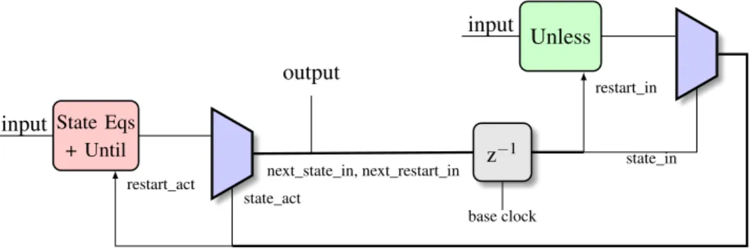
Unless z−1 State Eqs + Until input input next_state_in, next_restart_in base clock restart_act state_act state_in restart_in output
Figure 2: Automaton as a pure dataflow
developed in [7, 6], which is to the best of our knowledge the most disciplined and simple approach. This technique is also implemented in the commercial KCG Scade/Lustre compiler [9].
Informally, the modular compilation scheme developed in [7, 6] is enforced at the expense of raw (and somehow undesired) expressivity, disallowing for instance transitions that go through boundaries of hierarchical state machines or the firing of an unbounded number of transitions per instant (e.g. in Matlab Simulink and Stateflow). For instance, in Figure 2, at each instant, two pairs of variables are computed: a putative state_in and an actual state state_act and also, for both states, two booleans restart_in and restart_act, that tell whether their respective state equations should be reset before execution. The ac-tual state is obtained via a strong (unless) transition from the putative state, whereas the next putative state is obtained via a weak (until) transition from the actual state. Only the actual state equations are executed at each instant. Finally, a reset function is driven by the restart/resume keyword switches. As transition-firing conditions may have their own memories, they can be reset if needed before being evaluated. Specifically, unless conditions are reset according to restart_in, whereas until and state equations altogether are reset according to restart_act. To recapitulate, a transition is evaluated as fol-lows: unless conditions of the initial active state – the putative state – are evaluated. In case of a valid one, we jump to the associated state. Then, the state equations are evaluated: either the ones of the puta-tive state in case of no unless transitions activated, or the ones of the new state obtained. Then, as a last step, the until transition of the active state are evaluated and characterize the next state for the following transition. At most one unless and one until transitions are evaluated, in this order, at each time step.
Our approach, builds on top of the aforementioned compilation scheme. In our setting, we promote the computation of strong transition, state equations and weak transition to independent auxiliary Lustre nodes. This allows a certain flexibility: (i) independent scheduling and optimization of different state equations; (ii) addition of code contracts to different states. Those features are not supported by the commercial KCG suite. Another benefit of our approach is that we don’t modify state equations to take clock constraints, nor local variables or the reset operation. Local state information is only recovered through clock calculus and is not structural any more, as generated code may be optimized and scattered. We rather only encapsulate state equations in new node definitions and generate new equations for calling these nodes, greatly facilitating the management of local state invariants for instance. Yet, this comes at
the expense of a rather limited loss in expressivity, due to possible causality issues1. Note that inlining
these auxiliary nodes is already an available option that fully recovers the original semantics.
We illustrate in Listings. 1a, 1b and 1c, the differences between our approach and [7], from a user’s
1We recall that the classical causality analysis in modern Lustre doesn’t cross boundaries of nodes, hence the conservative
node f a i l u r e ( i :i n t ) r e t u r n s ( o1 , o2 : i n t ) ; l e t ( o1 , o2 ) = i f i = 0 then ( o2 , i ) e l s e ( i , o1 ) ; t e l
(a) Scheduling failure
node s o l u t i o n ( i :i n t ) r e t u r n s ( o1 , o2 : i n t ) ; l e t automaton c o n d i t i o n u n l e s s i <> 0 resume KO s t a t e OK: l e t ( o1 , o2 ) = ( o2 , i ) ; t e l s t a t e KO: u n l e s s i = 0 resume OK l e t ( o1 , o2 ) = ( i , o1 ) ; t e l t e l
(b) Automaton based solution node t r i a n g l e ( r :b o o l ) r e t u r n s ( o : i n t ) ; l e t automaton t r i v i a l s t a t e One : u n l e s s r | | p r e o = 100 l e t o = 0 −> 1 + p r e o ; t e l t e l (c) Causality issues
Listing 1: Examples comparing our approach with the one developed in [7]
viewpoint. Example 1a is a typical program that cannot be statically scheduled and produces a compi-lation error in both approaches. A solution may be devised as in Example 1b, using an automaton to encode the boolean switch i = 0. Even if scheduling is done prior to other static analyses (and thus is un-aware of exclusive automaton states for instance), we succeed in generating a correct code whereas KCG
fails. Example 1c is non-causal and won’t compile if we remove thepreoccurring in the unless clause.
But if we keep it, KCG will handle it correctly whereas our causality analysis will reject this program. Generally speaking, we forbid unless clauses that would refer to putative state memories (such as o). Accepting these clauses appear problematic or at least confusing as it makes the putative state visible and distinct from the actual state, thus duplicating state variables.
As a result our encoding is not strictly comparable with Scade or Lustre v6 automaton. For instance, we are unable to type check and compile automaton with memories within unless conditions. This is pos-sible in our setting. In summary, our encoding does not flatten the automaton into a single Lustre node but preserves the structure by associating a Lustre node for each automaton state. This structure preserv-ing encodpreserv-ing enables us to analyze these models and compute local invariants associated to automaton states.
3
Synchronous dataflow programs as Horn clauses
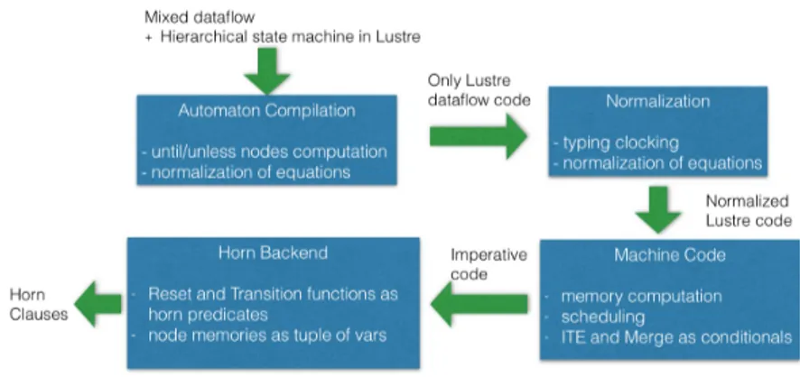
In [10] we have developed a compilation technique that translate Lustre programs into modular Horn clauses. In order to accommodate the compilation of automaton we have updated such compilation scheme. In this section, we briefly describe the different stages of the compilation process. For a formal treatment of the compilation stages the reader can refer to [10]. Figure 3 illustrate the compilation stages
implemented in LUSTREC.
Automaton compilation. The first phase, which is new w.r.t. [10], compiles the hierarchical states
machines as pure dataflow expression in Lustre. A detailed description of this phase will be presented in Section. 4.
Figure 3: Compilation Stages
Normalization. This phase infers types and clock for each signal. Each expression is recursively
normalized: node calls, pre constructs, tuples, . . . are defined as fresh variables. Each function call
f oo(args) is associated to a unique identifier f oouid(args). Once normalized, no function calls occurs
within expressions, nor arrows nor definitions of memories through a pre construct.
Machine code. In the main compiler process, intended to generate embedded code, the next phase
generates the machine (or imperative) code: its flows definitions are replaced by an ordered sequence of imperative statements. The state of a node instance is characterized by its memories, i.e. expressions defining memories such as x = pre e, and the node instances that appear in its expressions such as x = foo(. . .).
Generation of machine code. At this stage a machine code is generated. This amount to replace
the flow definitions with an ordered sequence of imperative statements. The state of a node instance is characterized by its memories, i.e. expressions defining memories such as x = pre e, and the node instances that appear in its expressions such as x = f oo(. . .). This tree-like characterization of a node state enable a modular definition of a state as a tree of local memories.
Definition 1 (Node memories and instances). Let f be a Lustre node with normalized equations eqs. Then we define its set of memories and node callee instances as:
Mems( f ) = {x | x = pre _ ∈ eqs}
Insts( f ) = {( f oo, uid) | _ = f oouid(_) ∈ eqs}
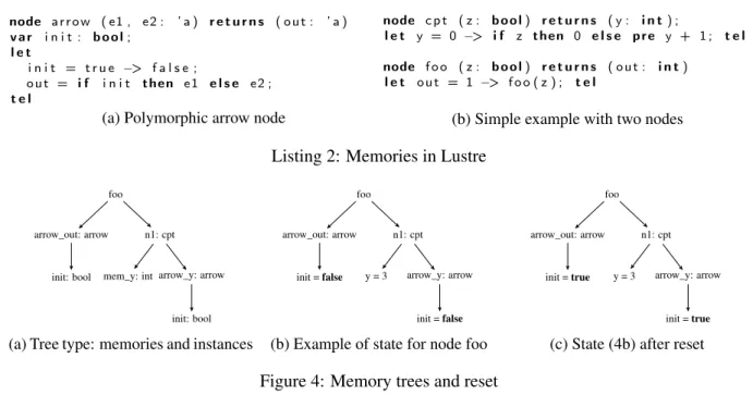
The follow by (→) operator is interpreted as a node instance of a generic polymorphic node arrow as illustrated in Listing 2a. Therefore the initial state for a node associated to all its arrow instances and all its child arrow instances the value true to the memory init . Similarly the activation of a node reset using the operator every modifies the state of this instance of the node foo by resetting its arrow init variable to their initial value true, e.g. e = foo (...) every ClockValue(clock_var). Figure 4 shows the computed memories of the node in Listing 2b.
Horn backend. At this stage the Horn clauses are generated. The hierarchy of memories and node
instances are flattened and modeled as a tuple of memories. We denote as statelabel (f, uid) the tuple
node a r r o w ( e1 , e2 : ’ a ) r e t u r n s ( o u t : ’ a ) v a r i n i t : b o o l ; l e t i n i t = t r u e −> f a l s e ; o u t = i f i n i t then e 1 e l s e e2 ; t e l
(a) Polymorphic arrow node
node c p t ( z : b o o l ) r e t u r n s ( y : i n t ) ;
l e t y = 0 −> i f z then 0 e l s e p r e y + 1 ; t e l node f o o ( z : b o o l ) r e t u r n s ( o u t : i n t )
l e t o u t = 1 −> f o o ( z ) ; t e l
(b) Simple example with two nodes
Listing 2: Memories in Lustre foo
arrow_out: arrow
init: bool
n1: cpt
mem_y: int arrow_y: arrow
init: bool
(a) Tree type: memories and instances
foo arrow_out: arrow init = false n1: cpt y = 3 arrow_y: arrow init = false
(b) Example of state for node foo
foo arrow_out: arrow init = true n1: cpt y = 3 arrow_y: arrow init = true
(c) State (4b) after reset
Figure 4: Memory trees and reset
between different versions of the same variable. We use the labels c and n to denote the (c)urrent and (n)ext value of a memory x: xcand xn. The internal node arrow is fitted with a specific reset rule:
r u l e (=> (= i n i tn t r u e ) ( a r r o w _ r e s e t ( i n i tc, i n i tn) ) )
Note that its state is only defined by the init variable. In the proposed encoding, the predicates defining the program semantics should enable the reset of a node state as performed in Fig. 4c. This leads to the following encoding for the reset function:
r u l e (=> ( ^ mem ∈ Mems(f) (= memn memc) ^ (g, uid) ∈ Inst(f) g _ r e s e t ( s t a t ec ( g , g u i d ) , s t a t en ( g , g u i d ) ) ) ( f _ r e s e t ( s t a t ec( f , u i d ) , s t a t en( f , u i d ) ) ) )
The collecting semantics definition of [10] is modified to rely on f_reset instead of f_init . It builds the set of reachable states (Reach):
r u l e (=> ( f _ r e s e t ( s t a t ec( f , u i d ) , s t a t en( f , u i d ) ) ) ( Reach ( s t a t en( f , u i d ) ) ) ) r u l e (=> ( and ( f _ s t e p ( i n p u t s , o u t p u t s , s t a t ec( f , u i d ) , s t a t en( f , u i d ) ) )
( Reach ( s t a t ec( f , u i d ) ) ) ) ( Reach ( s t a t en( f , u i d ) ) ) )
4
Compilation of automaton
In this section, we describe the compilation scheme from automaton to modular Horn clauses. This is performed in two stages: (i) compilation of automaton into clocked expressions and (ii) compilation of clocked expressions into Horn clauses.
4.1 From automaton to clocked expressions
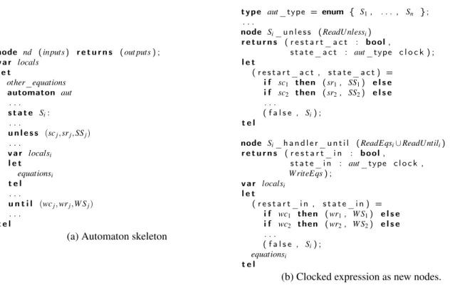
We denote with ReadEqsiand W riteEqsithe set of read and write variables occurring in equations of an
automaton state Si. We also denote as ReadU nlessi and ReadU ntili the set of variables in unless and
node nd ( inputs ) r e t u r n s ( out puts ) ; v a r locals l e t other_equations automaton aut . . . s t a t e Si: . . . u n l e s s (scj, srj, SSj) . . . v a r localsi l e t equationsi t e l . . . u n t i l (wcj, wrj,W Sj) . . . t e l
(a) Automaton skeleton
t y p e aut _type = enum { S1, . . . , Sn } ; . . .
node Si_ u n l e s s ( ReadU nlessi) r e t u r n s ( r e s t a r t _ a c t : b o o l , s t a t e _ a c t : aut _type c l o c k ) ; l e t ( r e s t a r t _ a c t , s t a t e _ a c t ) = i f sc1 then ( sr1, SS1) e l s e i f sc2 then ( sr2, SS2) e l s e . . . ( f a l s e , Si) ; t e l
node Si_ h a n d l e r _ u n t i l ( ReadEqsi∪ ReadUntili) r e t u r n s ( r e s t a r t _ i n : b o o l , s t a t e _ i n : aut _type c l o c k , W riteEqs) ; v a r localsi l e t ( r e s t a r t _ i n , s t a t e _ i n ) = i f wc1 then ( wr1, W S1) e l s e i f wc2 then ( wr2, W S2) e l s e . . . ( f a l s e , Si) ; equationsi t e l
(b) Clocked expression as new nodes.
Listing 3: Automaton in Lustre and their representation as clocked expressions in Lustre nodes.
Our compilation scheme from automaton to clocked expressions follows Figure 2 and is applied to a generic automaton such as the one described in Figure 3a (node nd). As illustrated in Listing 3b, the variables state_act and state_in are modelled as clocks of enumerated type. Also, two new nodes are introduced for each of the automaton state: one to express the semantics of state equations; and another one to capture the weak and strong transitions (as explained in Section 2).
Figure 4 illustrate the compiled node c_nd that replace the original automaton description of node nd. Evaluation of each single node call embedding state equations and transitions only takes place when its corresponding clock is active; this is done via “when Value(clock)” sampling operators applied to all node arguments.
All the node calls that corresponds to the global evaluation of the automaton are then gathered in two merge constructs, which are driven by the putative state clock state_in (for strong transitions) and the actual state clock state_act (for weak transitions and state equations).
4.2 Compiling clocked expressions into modular Horn clauses
Once the automaton structure as been compiled into clocked expression, the second step is to encode them as Horn clauses. Here, we use the Horn clause format introduced in Z3 [16], where (rule expr) universally quantify the free variables of the SMT-LIB expression expr. At this level, the challenges are to be able to express within the Horn formalism the following concepts: (i) the clock’s feature of Lustre, (ii) the reset functionality of a node, (iii) the declaration of enumerated clocks, (iv) clocked expression with the when operator, (v) merge of clocked expressions and reset of node state on conditionals with the every operator. In the following we illustrate how we capture using Horn clauses the above mentioned concepts.
node c_nd ( inputs ) r e t u r n s ( out puts ) ; v a r locals ;
aut_ r e s t a r t _ i n , aut _ n e x t _ r e s t a r t _ i n , aut _ r e s t a r t _ a c t : b o o l ; aut_ s t a t e _ i n , aut _ n e x t _ s t a t e _ i n , aut _ s t a t e _ a c t : aut _type c l o c k ; l e t
. . .
( aut _ r e s t a r t _ i n , aut _ s t a t e _ i n ) =
( f a l s e , S1) −> p r e ( aut _ n e x t _ r e s t a r t _ i n , aut _ n e x t _ s t a t e _ i n ) ; ( aut _ r e s t a r t _ a c t , aut _ s t a t e _ a c t ) = merge aut _ s t a t e _ i n
. . .
( Si −> Si_ u n l e s s ( ( ReadU nlessi) when Si( aut _ s t a t e _ i n ) ) e v e r y aut _ r e s t a r t _ i n ) . . .
( aut _ n e x t _ r e s t a r t _ i n , aut _ s t a t e _ n e x t _ i n , W riteEqs ) = merge aut _ s t a t e _ a c t . . .
( Si −> Si_ h a n d l e r _ u n t i l ( ( ReadEqsi∪ ReadUntili) when Si( aut _ s t a t e _ a c t ) ) e v e r y aut _ r e s t a r t _ a c t ) . . .
t e l
Listing 4: Compiled node c_nd from node nd in Figure 3a.
Clock values are defined as regular enumerated type in SMT-LIB format:
(d e c l a r e −d a t a t y p e s ( ) ( ( c l o c k _ t y p e S t a r t S t o p ) ) )
Combination of merge and when operator are required for the clock calculus (i.e. clock typing) but are ignored when generating the final code. Merge constructs act as a switch-case statement over well-clocked expression. For example, the following well-well-clocked Lustre expression:
s e c o n d s = merge r u n ( S t a r t −> x when S t a r t ( r u n ) ) ( S t o p −> y when S t o p ( r u n ) )
is translated to the imperative switch-case expression:
s w i t c h ( r u n ) { c a s e S t a r t : e = x ; b r e a k ; c a s e S t o p : e = y ; b r e a k }
Since each case definition is purely functional, this can be directly expressed as the following constraint:
(and (=> (= r u n S t a r t ) (= e x ) ) (=> (= r u n S t o p ) (= e y ) ) )
The next item is to capture the reset of a node’s state using the every operator,
e.g. count (x) every condition . During the compilation process, such expression generate a machine code instruction:
i f ( c o n d i t i o n ) { R e s e t ( c o u n t , u i d ) } ;
which gets translated to an imperative statement:
i f ( c o n d i t i o n ) { c o u n t _ r e s e t ( s t a t e _ c o u n t _ u i d ) } e l s e { } ;
where state_count_uid is a struct that denotes a node’s state instance. s This conditional statement will perform a side-effect update of the memory state and impact the computation of the next state and outputs. How do we capture this in the Horn encoding? Let us first look how we encode a step transition in Horn clauses. A step transition is basically a relationship (i.e. a predicate) between inputs, outputs, previous state and next state.
r e l a t i o n s h i p ( i n p u t s , o u t p u t s , o l d _ s t a t e , n e w _ s t a t e ) = (and ( . . . ) )
Typically this relationship would be used to define the step transition as follows:
r u l e (=> ( r e l a t i o n s h i p ( i n p u t s , o u t p u t s , s t a t ec( f , u i d ) , s t a t en( f , u i d ) ) ) ( f _ s t e p ( i n p u t s , o u t p u t s , s t a t ec( f , u i d ) , s t a t en( f , u i d ) ) ) )
node a u t o ( x : b o o l ) r e t u r n s ( o u t : b o o l ) ; l e t automaton f o u r _ s t a t e s s t a t e One : l e t o u t = f a l s e ; t e l u n t i l t r u e r e s t a r t Two s t a t e Two : l e t o u t = f a l s e ; t e l u n t i l t r u e r e s t a r t T h r e e s t a t e T h r e e : l e t o u t = t r u e ; t e l u n t i l t r u e r e s t a r t F o u r s t a t e F o u r : l e t o u t = f a l s e ; t e l u n t i l t r u e r e s t a r t One t e l
(a) Automaton-based counter
node g r e y c o u n t e r ( x : b o o l ) r e t u r n s ( o u t : b o o l ) ; v a r a , b : b o o l ; l e t a = f a l s e −> not p r e ( b ) ; b = f a l s e −> p r e ( a ) ; o u t = a and b ; t e l (b) Boolean-based counter node i n t l o o p c o u n t e r ( x :b o o l ) r e t u r n s ( o u t : b o o l ) ; v a r t i m e : i n t ; l e t t i m e = 0 −> i f p r e ( t i m e ) = 3 then 0 e l s e p r e t i m e + 1 ; o u t = ( t i m e = 2 ) ; t e l (c) Integer-based counter
Listing 5: Automaton-(5a), Boolean-(5b) and Integer-(5c) based implementation of a 2-bit counter.
For resetting the node’s state, the value used for the state is f_reset( statec(f,uid)) (instead of
statec(f,uid)). In addition to the two state labels used to denote current c and next value x, we
in-troduce an intermediate label i. In case of a transition without reset, the intermediate version would be directly defined as the current one.
r u l e (=> ( and (= ( s t a t ei( f , u i d ) ) ( s t a t ec( f , u i d ) ) )
( r e l a t i o n s h i p ( i n p u t s , o u t p u t s , s t a t ei( f , u i d ) , s t a t en( f , u i d ) ) ) ) ( f _ s t e p ( i n p u t s , o u t p u t s , s t a t ec( f , u i d ) , s t a t en( f , u i d ) ) ) )
Finally, the reset function is encoded as follows:
r u l e (=> ( and (= ( s t a t ei( f , u i d ) )
( i f c o n d i t i o n t h e n f _ r e s e t ( s t a t ec( f , u i d ) ) e l s e s t a t ec( f , u i d ) ) ) ( r e l a t i o n s h i p ( i n p u t s , o u t p u t s , s t a t ei( f , u i d ) , s t a t en( f , u i d ) ) ) ) ( f _ s t e p ( i n p u t s , o u t p u t s , s t a t ec( f , u i d ) , s t a t en( f , u i d ) ) ) )
5
Example of encoding
As an example of the proposed compilation process, we consider a simple Lustre program that compares three implementations of a 2-bit counter: a low-level Boolean implementation, a higher-level imple-mentation using integers and an automaton based counter. The greycounter node (cf. Fig. 5b) inter-nally repeats the sequence ab = {00, 01, 11, 10, 00, ...} indefinitely, while the integercounter node (cf. Fig. 5c) repeats the sequence time = {0, 1, 2, 3, 0, . . . }. The automaton based node (cf. Fig. 5a) is a state machines with 4 states and it basically alternates between them.
In the first phase of our compilation scheme a clock is generated to encode the automaton states:
t y p e auto_ck = enum {One , Two , Three , F o u r } ;
Each automaton state is associated to a stateless function describing respectively its strong (unless) tran-sitions and its weak (until) ones.
node a u t o ( x : b o o l ) r e t u r n s ( o u t : b o o l ) v a r m e m _ r e s t a r t : b o o l ; mem_state : auto_ck ; f o u r _ r e s t a r t _ i n : b o o l ; f o u r _ s t a t e _ i n : auto_ck ; f o u r _ o u t : b o o l ; f o u r _ r e s t a r t _ a c t : b o o l ; f o u r _ r e s t a r t _ i n : auto_ck ; . . . −− s i m i l a r d e c l a r a t i o n s f o r o t h e r s t a t e s n e x t _ r e s t a r t _ i n : b o o l ; r e s t a r t _ i n : b o o l ; r e s t a r t _ a c t : b o o l ; n e x t _ s t a t e _ i n : auto_ck ; s t a t e _ i n : auto_ck c l o c k ; s t a t e _ a c t : auto_ck c l o c k ; l e t
r e s t a r t _ i n , s t a t e _ i n = ( ( f a l s e , One ) −> ( mem_restart , mem_state ) ) ; mem_restart , mem_state = p r e ( n e x t _ r e s t a r t _ i n , n e x t _ s t a t e _ i n ) ; n e x t _ r e s t a r t _ i n , n e x t _ s t a t e _ i n , o u t =
merge s t a t e _ a c t ( One −> . . . ) ( Two −> . . . ) ( T h r e e −> . . . )
( F o u r −> ( f o u r _ r e s t a r t _ i n , f o u r _ s t a t e _ i n , f o u r _ o u t ) ) ; f o u r _ r e s t a r t _ i n , f o u r _ s t a t e _ i n , f o u r _ o u t = F o u r _ h a n d l e r _ u n t i l ( r e s t a r t _ a c t when F o u r ( s t a t e _ a c t ) , s t a t e _ a c t when F o u r ( s t a t e _ a c t ) ) e v e r y ( r e s t a r t _ a c t ) ; . . . −− s i m i l a r d e f i n i t i o n s f o r o t h e r s t a t e s r e s t a r t _ a c t , s t a t e _ a c t = merge s t a t e _ i n ( One −> . . . ) ( Two −> . . . ) ( T h r e e −> . . . ) ( F o u r −> ( f o u r _ r e s t a r t _ a c t , f o u r _ s t a t e _ a c t ) ) ; f o u r _ r e s t a r t _ a c t , f o u r _ s t a t e _ a c t = F o u r _ u n l e s s ( r e s t a r t _ i n when F o u r ( s t a t e _ i n ) , s t a t e _ i n when F o u r ( s t a t e _ i n ) ) e v e r y ( r e s t a r t _ i n ) ; . . . −− s i m i l a r d e f i n i t i o n s f o r o t h e r s t a t e s t e l
Listing 6: Generated Lustre code without automaton.
To keep the presentation simpler we present the encoding of the state Four:
f u n c t i o n F o u r _ h a n d l e r _ u n t i l ( r e s t a r t _ a c t : b o o l ; s t a t e _ a c t : auto_ck ) r e t u r n s ( r e s t a r t _ i n : b o o l ; s t a t e _ i n : auto_ck ; o u t : b o o l ) l e t −− e n c o d e s t h e n e x t s t a t e , h e r e One r e s t a r t _ i n , s t a t e _ i n = ( t r u e , One ) ; o u t = f a l s e ;−− r e t u r n s t r u e i n t h e h a n d l e r f o r s t a t e T h r e e t e l
The handler and the until function assigns the next state to the state One and require the node to be restarted. Listing 6 shows the generated Lustre node without an automaton.
The next stage of the compiler produces the Horn clauses. Enumerated type enable the declaration of clock’s values:
(d e c l a r e −d a t a auto_ck ( ) ( ( auto_ck One Two T h r e e F o u r ) ) )
The functions for until and unless are defined as Horn predicates (Four_handler_until and Four_unless respectively) in the following way:
(d e c l a r e − r e l F o u r _ h a n d l e r _ u n t i l ( B o o l auto_ck B o o l auto_ck B o o l ) ) (r u l e (=> ( and (= o u t f a l s e ) (= s t a t e _ i n One ) (= r e s t a r t _ i n t r u e ) ) ( F o u r _ h a n d l e r _ u n t i l r e s t a r t _ a c t s t a t e _ a c t r e s t a r t _ i n s t a t e _ i n o u t ) ) ) (d e c l a r e − r e l F o u r _ u n l e s s ( B o o l auto_ck B o o l auto_ck ) ) (r u l e (=> ( and (= s t a t e _ a c t s t a t e _ i n ) (= r e s t a r t _ a c t r e s t a r t _ i n ) ) ( F o u r _ u n l e s s r e s t a r t _ i n s t a t e _ i n r e s t a r t _ a c t s t a t e _ a c t ) ) )
Finally the reset (auto_reset) and step (auto_step) predicates are defined as follows respectively:
(r u l e (=> ( and (= mem_restart_m mem_restart_c ) (= mem_state_m mem_state_c ) (= a r r o w . i n i t _ m t r u e ) ) ( a u t o _ r e s e t mem_restart_c mem_state_c a r r o w . i n i t _ c mem_restart_m mem_state_m a r r o w . i n i t _ m ) ) ) (r u l e (=> (and (= a r r o w . i n i t _ m a r r o w . i n i t _ c ) (= a r r o w . i n i t _ x f a l s e ) −− u p d a t e o f a r r o w s t a t e (and (=> (= a r r o w . i n i t _ m t r u e ) −− c u r r e n t a r r o w i s f i r s t (and (= s t a t e _ i n One ) (= r e s t a r t _ i n f a l s e ) ) ) (=> (= a r r o w . i n i t _ m f a l s e ) −− c u r r e n t a r r o w i s n o t f i r s t (and (= s t a t e _ i n mem_state_c ) (= r e s t a r t _ i n mem_restart_c ) ) ) ) (and (=> (= s t a t e _ i n F o u r ) −− u n l e s s b l o c k f o r a u t o m a t o n s t a t e F o u r (and ( F o u r _ u n l e s s r e s t a r t _ i n s t a t e _ i n f o u r _ r e s t a r t _ a c t f o u r _ s t a t e _ a c t ) (= s t a t e _ a c t f o u r _ s t a t e _ a c t ) (= r e s t a r t _ a c t f o u r _ r e s t a r t _ a c t ) ) ) . . . ) −− s i m i l a r d e f i n i t i o n f o r o t h e r s t a t e s (and (=> (= s t a t e _ a c t F o u r ) −− h a n d l e r and u n t i l b l o c k f o r s t a t e F o u r (and ( F o u r _ h a n d l e r _ u n t i l r e s t a r t _ a c t s t a t e _ a c t f o u r _ r e s t a r t _ i n f o u r _ s t a t e _ i n f o u r _ o u t ) (= o u t f o u r _ o u t ) (= n e x t _ s t a t e _ i n f o u r _ s t a t e _ i n ) (= n e x t _ r e s t a r t _ i n f o u r _ r e s t a r t _ i n ) ) ) . . . ) −− s i m i l a r d e f i n i t i o n f o r o t h e r s t a t e s
(= mem_state_x n e x t _ s t a t e _ i n ) −− n e x t v a l u e f o r memory mem_state
(= mem_restart_x n e x t _ r e s t a r t _ i n ) ) −− n e x t v a l u e f o r memory m e m _ r e s t a r t ( a u t o _ s t e p x −− i n p u t s
o u t −− o u t p u t s
mem_restart_c mem_state_c a r r o w . i n i t _ c −− o l d s t a t e mem_restart_x mem_state_x a r r o w . i n i t _ x ) ) ) −− new s t a t e
Once the Horn clauses are generated, a Horn clause solver can be used to perform verification and/or testing. For example, we used Spacer [18] to prove that the three implementation of the 2-bit counters behaves the same (i.e. each implementation outputs the stream true).
6
Conclusion
In this paper, we proposed a new compilation scheme to faithfully compile a mix of dataflow formalism and hierarchical state machines into modular Horn clauses. Our approach compile hierarchical state machines expressed as automata in the Lustre language into modular Horn clauses. The compilation technique preserves the structural and modal behavior of the system which makes the analysis of such
models more tractable. The proposed approach is implemented in LUSTREC– an open source Lustre
compiler. Once the modular Horn clauses are generated, automated reasoning tools like Spacer [18] can be used to reason about properties. In the future, we plan to evaluate our compilation scheme on larger industrial case studies.
References
[1] P. Amagbégnon, L. Besnard & P. Le Guernic (1995): Implementation of the Data-flow Synchronous Language SIGNAL. In: Conference on Programming Language Design and Implementation, ACM Press, pp. 163–173, doi:10.1145/207110.207134.
[2] Albert Benveniste, Paul Caspi, Stephen A. Edwards, Nicolas Halbwachs, Paul Le Guernic & Robert de Si-mone (2003): The synchronous languages 12 years later. Proceedings of the IEEE 91(1), pp. 64–83, doi:10.1109/JPROC.2002.805826.
[3] G. Berry & G. Gonthier (1992): The ESTEREL synchronous programming language: design,
semantics, implementation. Sci. Comput. Program. 19(2), pp. 87–152, doi:10.1016/0167-6423(92)90005-V. [4] Dariusz Biernacki, Jean-Louis Colaço, Grégoire Hamon & Marc Pouzet (2008): Clock-directed modu-lar code generation for synchronous data-flow languages. In Krisztián Flautner & John Regehr, ed-itors: Proceedings of the 2008 ACM SIGPLAN/SIGBED Conference on Languages, Compilers, and Tools for Embedded Systems (LCTES’08), Tucson, AZ, USA, June 12-13, 2008, ACM, pp. 121–130, doi:10.1145/1375657.1375674.
[5] Paul Caspi, Daniel Pilaud, Nicolas Halbwachs & John Plaice (1987): Lustre: A Declarative Language for Programming Synchronous Systems. In: Conference Record of the Fourteenth Annual ACM Symposium on Principles of Programming Languages, Munich, Germany, January 21-23, 1987, ACM Press, pp. 178–188, doi:10.1145/41625.41641.
[6] Jean-Louis Colaço, Grégoire Hamon & Marc Pouzet (2006): Mixing signals and modes in synchronous data-flow systems. In Sang Lyul Min & Wang Yi, editors: Proceedings of the 6th ACM & IEEE International conference on Embedded software, EMSOFT 2006, October 22-25, 2006, Seoul, Korea, ACM, pp. 73–82, doi:10.1145/1176887.1176899.
[7] Jean-Louis Colaço, Bruno Pagano & Marc Pouzet (2005): A conservative extension of synchronous data-flow with state machines. In Wayne Wolf, editor: EMSOFT 2005, September 18-22, 2005, Jersey City, NJ, USA, 5th ACM International Conference On Embedded Software, Proceedings, ACM, pp. 173–182, doi:10.1145/1086228.1086261.
[8] DO-178b: Software Considerations in Airborne Systems and Equipment Certification.
[9] Inc. Esterel Technologies: SCADE. Available at http://www.esterel-technologies.com/products/ scade-suite/.
[10] Pierre-Loïc Garoche, Arie Gurfinkel & Temesghen Kahsai (2014): Synthesizing Modular Invariants for Syn-chronous Code. In Nikolaj Bjørner, Fabio Fioravanti, Andrey Rybalchenko & Valerio Senni, editors: Pro-ceedings First Workshop on Horn Clauses for Verification and Synthesis, HCVS 2014, Vienna, Austria, 17 July 2014., EPTCS 169, pp. 19–30, doi:10.4204/EPTCS.169.4.
[11] Pierre-Loïc Garoche, Temesghen Kahsai & Xavier Thirioux: LustreC. Available at https://github.com/ coco-team/lustrec.
[12] N. Halbwachs, P. Caspi, P. Raymond & D. Pilaud (1991): The synchronous dataflow programming language LUSTRE. In: Proceedings of the IEEE, pp. 1305–1320, doi:10.1109/5.97300.
[13] Grégoire Hamon & John M. Rushby (2004): An Operational Semantics for Stateflow. In Michel Wermelinger & Tiziana Margaria, editors: Fundamental Approaches to Software Engineering, 7th International Confer-ence, FASE 2004, Held as Part of the Joint European Conferences on Theory and Practice of Software, ETAPS 2004 Barcelona, Spain, March 29 - april 2, 2004, Proceedings, Lecture Notes in Computer Science 2984, Springer, pp. 229–243, doi:10.1007/978-3-540-24721-0_17.
[14] David Harel (1987): Statecharts: A Visual Formalism for Complex Systems. Sci. Comput. Program. 8(3), pp. 231–274, doi:10.1016/0167-6423(87)90035-9.
[15] David Harel & Michal Politi (1998): Modeling Reactive Systems with Statecharts: The Statemate Approach, 1st edition. McGraw-Hill, Inc., New York, NY, USA.
[16] Kryštof Hoder & Nikolaj Bjørner (2012): Generalized Property Directed Reachability. In Alessandro Cimatti & Roberto Sebastiani, editors: Theory and Applications of Satisfiability Testing – SAT 2012, LNCS 7317, pp. 157–171, doi:10.1007/978-3-642-31612-8_13.
[17] Temesghen Kahsai & Cesare Tinelli (2011): PKind: A parallel k-induction based model checker. In Jiri Barnat & Keijo Heljanko, editors: Proceedings 10th International Workshop on Parallel and Distributed
Methods in verifiCation, PDMC 2011, Snowbird, Utah, USA, July 14, 2011., EPTCS 72, pp. 55–62, doi:10.4204/EPTCS.72.6.
[18] Anvesh Komuravelli, Arie Gurfinkel, Sagar Chaki & Edmund M. Clarke (2013): Automatic Abstraction in SMT-Based Unbounded Software Model Checking. In Natasha Sharygina & Helmut Veith, editors: Com-puter Aided Verification - 25th International Conference, CAV 2013, Saint Petersburg, Russia, July 13-19, 2013. Proceedings, Lecture Notes in Computer Science 8044, Springer, pp. 846–862, doi:10.1007/978-3-642-39799-8_59.
[19] Florence Maraninchi & Yann Rémond (1998): Mode-automata: About modes and states for reactive systems. In Chris Hankin, editor: Programming Languages and Systems, Lecture Notes in Computer Science 1381, Springer Berlin Heidelberg, pp. 185–199, doi:10.1007/BFb0053571.
[20] Inc. The MathWorks: Simulink. Available at http://www.mathworks.com/products/simulink/. [21] Inc. The MathWorks: Stateflow. Available at http://www.mathworks.com/products/stateflow/. [22] Andrew C. Uselton & Scott A. Smolka (1994): A Compositional Semantics for Statecharts using Labeled
Transition Systems. In Bengt Jonsson & Joachim Parrow, editors: CONCUR ’94, Concurrency Theory, 5th International Conference, Uppsala, Sweden, August 22-25, 1994, Proceedings, Lecture Notes in Computer Science 836, Springer, pp. 2–17, doi:10.1007/BFb0014994.