Tuning the Performance and the Stability of Porous Hollow PtNi/C
Nanostructures for the Oxygen Reduction Reaction
Laetitia Dubau,
*
,†,‡Tristan Asset,
†,‡Raphaël Chattot,
†,‡Céline Bonnaud,
†,‡Victor Vanpeene,
†,‡Jaysen Nelayah,
⊥and Frédéric Maillard
*
,†,‡†University of Grenoble Alpes, LEPMI, F-38000 Grenoble, France ‡CNRS, LEPMI, F-38000 Grenoble, France
⊥Laboratoire Matériaux et Phénomènes Quantiques (MPQ), UMR 7162 CNRS & Université Paris-Diderot, Bâtiment Condorcet, 4 rue Elsa Morante, F-75205 Paris Cedex 13, France
*
S Supporting InformationABSTRACT: Due to their increased surface area to volume ratio and molecular accessibility, microporous and mesoporous materials are a promising strategy to electrocatalyze the cathodic oxygen reduction reaction (ORR), the key reaction in proton-exchange membrane fuel cells (PEMFC). Here, we synthesized and provided atomically resolved pictures of porous hollow PtNi/C nanocatalysts, investigated the elemental distribution of Ni and Pt atoms, measured the Pt lattice contraction, and correlated these observations to their ORR activity. The best porous hollow PtNi/C nanocatalyst achieved 6 and 9-fold enhancement in mass and specific
activity for the ORR, respectively over standard solid Pt/C nanocrystallites of the same size. The catalytic enhancement was 4 and 3-fold in mass and specific activity, respectively, over solid PtNi/C nanocrystallites with similar chemical composition, Pt lattice contraction, and crystallite size. Furthermore, 100% of the initial mass activity at E = 0.90 V vs RHE (0.56 A mg−1Pt) of the best electrocatalyst was retained after an accelerated stress test composed of 30 000 potential cycles between 0.60 and 1.00 V vs RHE (0.1 M HClO4T = 298 K), therefore meeting the American Department of Energy targets for 2017−2020 both in terms of mass activity and durability (0.44 A mg−1Pt, mass activity losses < 40%). The better catalytic activity for the ORR of hollow PtNi/C nanocatalysts is ascribed to (i) their opened porosity, (ii) their preferential crystallographic orientation (“ensemble effect”), and (iii) the weakened oxygen binding energy induced by the contracted Pt lattice parameter (“strain effect”).
KEYWORDS: platinum, hollow nanoparticles, galvanic replacement, oxygen reduction reaction, proton exchange membrane fuel cell, nanoporosity, durability
■
INTRODUCTIONHighly dispersed nanomaterials are widely used in heteroge-neous catalysis to improve the surface area to volume ratio, and thus to provide cost savings. Because they exhibit unusual chemical and physical properties, different from those of the bulk material, the catalytic properties of nanoparticles are unique. It is well-established that a change in size of a metal nanoparticle results into: (i) a variation of the mean coordination number,1 (ii) a change of the equilibrium shape,2(iii) a shift of the d-band center relative to the Fermi level,2−5 and (iv) an expansion or a contraction of the lattice parameter.6,7 Strikingly, despite specific cases such as the oxidation of carbon monoxide (CO) on Au nanoparticles,8,9the intrinsic catalytic activity is usually depreciated when decreasing the metal nanoparticle size.4,5 This holds particularly true in proton-exchange membrane fuel cells (PEMFCs), where Pt-based nanoparticles supported onto a high-surface area carbon electrocatalyze the hydrogen oxidation reaction (HOR) and the oxygen reduction reaction (ORR).1,4,5,10−18 The specific
activity (SA, the kinetic current normalized to a square centimeter of Pt) for the ORR decreases by a factor of 4 going from bulk Pt to 2 nm-sized crystallites.12−14,18 Concomitantly, the mass activity (MA, the kinetic current per unit mass of Pt) reaches a maximum at around 3−4 nm. This trend is believed to be related to the increasing surface fraction of undercoordinated sites (edges, corners and vertices), which bind strongly to the ORR intermediates (OH, OOH, and O).1,11,15,18,19The high fraction of undercoordinated sites also depreciates the long-term stability of the smallest Pt-based/C nanocrystallites (their higher surface energy causes increased driving force for dissolution and faster electrochemical dissolution kinetics).20 In consequence, metal nanocrystallites ca. 4−5 nm in size represent the best compromise between Received: April 9, 2015
Revised: July 27, 2015
Published: July 28, 2015
ORR activity and stability to date, and only new catalyst architectures may allow changing the picture.
In the past decade, Pt-transition metal alloy nanoparticles (Pt-M/C where M is an early or late21−26 transition metal) revealed great potential to accelerate the ORR kinetics. The catalytic enhancement over pure Pt/C has been attributed to the weakening of the chemisorption energies of the ORR intermediates via strain21,27−30 and ligand31−33 effects. Un-fortunately, whatever their initial structure (alloy, core−shell, skin/skeleton type electrocatalysts), considerable losses in catalytic activity were observed during long-term PEMFC operation.34−39 Combined physical, chemical, and electro-chemical techniques bridged these losses to the (i) decreased intrinsic catalytic activity due to M dissolution and the formation of a thick enriched shell covering the initial Pt-M/C electrocatalyst,34−36,40−42 (ii) depreciated H+/O2
mass-transport properties of the catalytic layer ionomer/proton exchange membrane (PEM),43−45and (iii) enhanced formation of radical species in the PEM.43In this context, we and other groups showed that, under specific PEMFC aging conditions, the dissolution of Co atoms from Pt3Co/C nanoparticles leads to the formation of hollow Pt-rich nanostructures (i.e., containing a Pt-rich shell surrounding a central void) with enhanced ORR activity.36−38,40 The formation of these nanostructures was accounted for by a nanoscale Kirkendall effect, which is a vacancy-mediated diffusion mechanism in binary Pt-M alloys or M-core@Pt-shell materials driven by the faster interdiffusion of one element relative to the other.46−51
Taking inspiration from the structural and chemical changes occurring on Pt3Co/C nanoparticles during real PEMFC life,
we recently synthesized hollow PtCo/C38 or PtNi/C52 nanocrystallites via a one-pot process involving galvanic replacement (an electrochemical process in which the oxidation of the non-noble metal nanocrystallites provides electrons for the deposition of Ptz+ ions onto their outer surface) and the
nanoscale Kirkendall effect. In a typical synthesis, Pt(NH3)4Cl2·
(H2O), NiCl2·(6H2O), and NaBH4 are mixed with Vulcan XC72R, ethanol, and deionized water (Figure 1). Based on
recent results from Shan et al.,53 Ni−B/C compounds are believed to formfirst, therefore acting as sacrificial templates for the deposition of Pt atoms via galvanic replacement. The deposition of Pt atoms likely proceeds on preferential regions of the sacrificial Ni-rich/C nanoparticles yielding nanometre-sized PtNi/C clusters, which grow in close proximity to each other, and coalesce as the reduction of Pt2+ ions proceeds. Ultimately, an acid leaching treatment (22 h in a stirred 1 M H2SO4 solution at T = 293 K) ensures the dissolution of
unreacted Ni-rich regions and the formation of Pt-enriched surface layers.
This study describes the synthesis and the atomic-scale characterization of hollow PtNi/C nanoparticles with different metal shell thickness and different size of the central cavity. These nanocatalysts combine opened porosity, compressed Pt lattice constant, and preferential crystallographic orientation, which result in 6 and 9-fold enhancement in mass and specific activity for the ORR, respectively over standard solid Pt/C nanocrystallites of the same size.
■
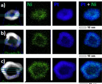
RESULTS AND DISCUSSIONFigure 2displays high resolution high angle annular dark field scanning transmission electron microscopy (HAADF-STEM)
images, line-scan analyses, and X-ray energy dispersive spectroscopy (X-EDS) elemental maps of the electrocatalysts synthesized by varying the Pt:Ni atomic ratio in the initial metal salt precursor solution from 1:1 to 1:5 (note that the Pt2+
concentration was kept constant and only the Ni2+ concen-tration varied). More images and elemental maps can be found inSupplementary Figure S1.
The PtNi/C nanoparticles feature irregular shape, and sizes comprised between ca. 10 and 15 nm. Their central portion is darker than their surface, therefore suggesting a core−shell or a hollow nanostructure. X-EDS global and line-scan analyses as well as elemental maps reveal that (i) hollow-type PtNi/C nanoparticles largely predominate, (ii) Ni and Pt atoms are homogeneously distributed within the metal shell but, as a result of acid leaching,54 the surface and near-surface of the catalysts are enriched in Pt, and (iii) whatever the Pt:Ni ratio in the metal salt precursor solution, the Ni content estimated by X-EDS over eight different zones is close to 10 at % (Table 1). The slightly larger Ni content found by atomic absorption spectrometry (AAS) confirms our former results that the electrocatalyst contains a small fraction of solid Ni-rich core@ Pt-rich shell nanoparticles.52 To demonstrate the catalytic advantages of a hollow nanoarchitecture, solid PtNi/C nanoparticles with similar chemical composition, Pt lattice contraction and crystallite size were synthesized via a modified
Figure 1.Schematic illustration of the procedure used to synthesize hollow Pt-rich nanoparticles. As described in theExperimental Section, all the chemical compounds are mixed simultaneously but Ni-rich/C nanocrystallites are believed to formfirst.
Figure 2. HAADF-STEM images, line scan analysis, and X-EDS elemental maps of hollow PtNi/C nanoparticles. The Pt:Ni stoichiometry in the initial metal salt precursor solution was (a) 1:1, (b) 1:3, and (c) 1:5. More HAADF-STEM images can be found in
polyol method (see theExperimental Section). For the sake of clarity, in what follows, the hollow electrocatalysts will be referred to as Pt:Ni (initial stoichiometry)/C (e.g. PtNi (1:5)/ C when the Pt:Ni stoichiometry in the metal salt precursor solution was 1:5).
Figure 3illustrates the morphological and structural changes occurring on the hollow PtNi/C nanoparticles upon changing
the Pt:Ni stoichiometry in the metal salt precursor solution. A decrease of the initial Pt:Ni ratio from 1:1 to 1:5 caused an increase in the size of the central void from 5.9 to 7.6 nm in average and a thinning of the Pt-rich shell from 3.9 to 2.6 nm, respectively (Table 2).
Further insights into the atomic structure of the hollow PtNi/C nanoparticles were obtained by aberration-corrected
high-resolution transmission electron microscopy (HR-TEM). The HR-TEM image of PtNi (1:3)/C shown in Figure 4c
indicates that the metal shell is composed of nanocrystallites of various sizes and crystallographic orientations interconnected by grain boundaries. Figure 4d and e shows aberration-corrected HR-TEM images from two distinct regions of the surface of the particle shown inFigure 4c. InFigure 4d, the d spacing of 0.226 nm averaged on 4−5 atomic rows allowed identifying (111) lattice planes in a face-centered cubic (fcc) PtNi phase. An adisland with monotonic height (indicated by red arrows) is also clearly visible, in agreement with former observations performed by Strmcnik et al.55on Pt(hkl) single crystals. In Figure 4e, we noticed the presence of grain boundaries in the metal shell along with a re-entrant corner (indicated by red arrows). Note that the broad distribution of interplanar distances and angles in this region prohibits any clear indexation of the different crystal planes in presence.
Aberration-correction HR-TEM images also revealed atomic details out of reach for conventional microscopes. For example, inFigure 5a, a discontinuity of the PtNi shell is evidenced in the center of the nanoparticle. Fourier transform (FT) analyses of the HR-TEM image in the center of the particle (red square zone) and in the metal shell (yellow square zone) are shown in insets (top-right and bottom-right, respectively). In the center of the nanoparticle, the FT pattern is structureless due to the Table 1. Structural and Chemical Parameters of the
Electrocatalysts Evaluated in This WorkAtomic
Composition Determined by X-EDS or AAS and Pt Lattice Parameter Measured by X-ray Diffraction
X-EDS AAS XRD at. comp (%) lattice parameter (nm) lattice parameter contraction vs Pt/C (%) solid Pt/C Pt100Ni0 Pt100Ni0 0.3930 0 solid PtNi/C Pt90±4Ni10±4 Pt84±1Ni16±1 0.3864 1.7 hollow PtNi (1:1)/C Pt91±2Ni9±2 Pt86±1Ni14±1 0.3881 1.2 hollow PtNi (1:2)/C Pt90±2Ni10±2 0.3874 1.4 hollow PtNi (1:3)/C Pt85±2Ni15±2 Pt79±1Ni21±1 0.3855 1.9 hollow PtNi (1:5)/C Pt87±2Ni13±2 Pt77±1Ni23±1 0.3858 1.8
Figure 3.TEM images and histograms of the Pt-rich shell thickness and of the outer diameter of the hollow PtNi/C nanoparticles. The Pt:Ni stoichiometry in the initial metal salt precursor solution is indicated in the top right-hand side corner of individual histograms/ images.
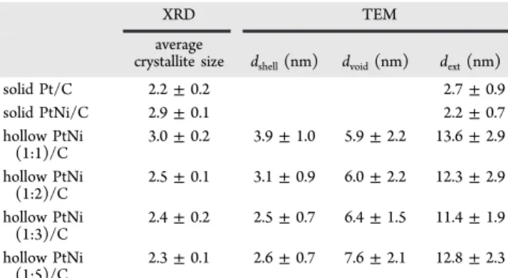
Table 2. Structural Parameters of the Electrocatalysts Evaluated in This Worka
XRD TEM
average
crystallite size dshell(nm) dvoid(nm) dext(nm)
solid Pt/C 2.2± 0.2 2.7± 0.9 solid PtNi/C 2.9± 0.1 2.2± 0.7 hollow PtNi (1:1)/C 3.0± 0.2 3.9± 1.0 5.9± 2.2 13.6± 2.9 hollow PtNi (1:2)/C 2.5± 0.1 3.1± 0.9 6.0± 2.2 12.3± 2.9 hollow PtNi (1:3)/C 2.4± 0.2 2.5± 0.7 6.4± 1.5 11.4± 1.9 hollow PtNi (1:5)/C 2.3± 0.1 2.6± 0.7 7.6± 2.1 12.8± 2.3
aAverage crystallite size estimated from XRD spectra, PtNi shell
thickness, and size of the inner central void and of the outer metal layer statistically determined by TEM.
Figure 4.Aberration corrected HR-TEM images of the hollow PtNi (1:3)/C nanoparticles. (a and b) Assemblies of PtNi (1:3)/C nanoparticles imaged at 250 000 and 400 000× nominal magnification, respectively. (c) a HR-TEM image of a single PtNi (1:3)/C nanoparticle. Zoom-in images at the particle surface are shown in part d and e. Arrows are used to highlight different structural defects. ACS Catalysis
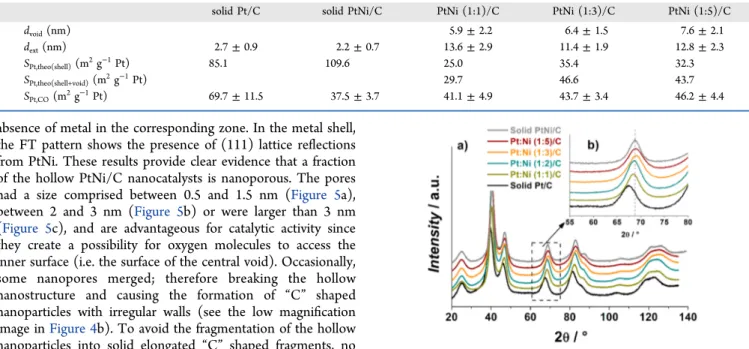
absence of metal in the corresponding zone. In the metal shell, the FT pattern shows the presence of (111) lattice reflections from PtNi. These results provide clear evidence that a fraction of the hollow PtNi/C nanocatalysts is nanoporous. The pores had a size comprised between 0.5 and 1.5 nm (Figure 5a), between 2 and 3 nm (Figure 5b) or were larger than 3 nm (Figure 5c), and are advantageous for catalytic activity since they create a possibility for oxygen molecules to access the inner surface (i.e. the surface of the central void). Occasionally, some nanopores merged; therefore breaking the hollow nanostructure and causing the formation of “C” shaped nanoparticles with irregular walls (see the low magnification image inFigure 4b). To avoid the fragmentation of the hollow nanoparticles into solid elongated “C” shaped fragments, no catalyst with initial Pt:Ni stoichiometry smaller than 1:5 was synthesized.
To confirm that the inner surface (the surface of the central void) and the atoms located along the nanopores are electrochemically active, the Pt specific surface area of the synthesized electrocatalysts (SPt,CO) was calculated using the
coulometry of a COadstripping experiment and compared to
the theoretical values calculated assuming cuboctahedral particle shape and a stoichiometry of 1 CO molecule per Pt atom. Table 3 shows that, if only the outer surface is considered, the theoretical Pt specific surface area (“SPt,theo(shell)”) is 25−50% inferior to that measured
exper-imentally (SPt,CO). A good agreement with SPt,CO is obtained
when both the inner and the outer surfaces (“SPt,theo(shell+void)”)
are considered electrochemically active (Table 3).
The fcc structure of the synthesized hollow and the solid PtNi/C electrocatalysts was confirmed using XRD (Figure 6). For all nanoalloys, the X-ray reflections shifted toward larger 2θ angles, indicating a contracted Pt lattice parameter vs. solid Pt/ C nanocrystallites of the same size. As shown byTable 1, the Pt lattice parameter was contracted by ca. 1.2, 1.9, and 1.8% vs pure Pt/C for initial Pt:Ni stoichiometries of 1:1, 1:3, and 1:5, respectively. Moreover, the similar Pt lattice constant measured on the solid PtNi/C and the hollow PtNi (1:3)/C and PtNi (1:5)/C electrocatalysts guaranteed a fair demonstration of the catalytic advantage provided by a hollow nanoarchitecture.
Insights into the surface reactivity of the porous hollow PtNi/C nanoparticles were gained by probing the adsorption/ desorption of underpotentially deposited hydrogen (Hupd)
between 0.05 < E < 0.40 V vs RHE. Similar Hupdadsorption/ desorption features were observed on the solid Pt/C and PtNi/ C electrocatalysts and the synthesized porous hollow PtNi/C nanoparticles (Figure 7a): this confirms the conclusions derived from X-EDS elemental maps that the surface of the synthesized nanomaterials is essentially pure Pt. However, increased charge density was noticed in the region of“strongly-bound” hydrogen (0.25 < E < 0.40 V vs RHE); therefore, pointing toward a larger surface fraction of (100) + (111) facets on the hollow porous PtNi/C nanoparticles vs the two reference materials.56−58
Preferential crystallographic orientation was probed by calculating the texture coefficients (TCs) of the synthesized nanocatalysts. The TC values were determined by comparing the intensities of the diffraction peaks monitored on the PtNi/ C nanoparticles with those of the reference Pt/C 20 wt % material:59
Figure 5.HR-TEM images of hollow porous PtNi/C nanoparticles (initial Pt:Ni stoichiometry = 1:3) with pores ca. (a) 1.0, (b) 2.0, and (c) >3.0 nm in size. The FT patterns of the zones marked in part a are inserted in the right part of thefigure (FFT of the center of the nanoparticle at the bottom right of the image).
Table 3. Theoretical and Measured Pt Specific Surface Area for the Electrocatalysts Evaluated in This Work
solid Pt/C solid PtNi/C PtNi (1:1)/C PtNi (1:3)/C PtNi (1:5)/C
dvoid(nm) 5.9± 2.2 6.4± 1.5 7.6± 2.1
dext(nm) 2.7± 0.9 2.2± 0.7 13.6± 2.9 11.4± 1.9 12.8± 2.3
SPt,theo(shell)(m2g−1Pt) 85.1 109.6 25.0 35.4 32.3
SPt,theo(shell+void)(m2g−1Pt) 29.7 46.6 43.7
SPt,CO(m2g−1Pt) 69.7± 11.5 37.5± 3.7 41.1± 4.9 43.7± 3.4 46.2± 4.4
Figure 6.(a) X-ray diffraction patterns of the porous hollow PtNi/C and the reference solid Pt/C and PtNi/C electrocatalysts and (b) close-up in the 60° < 2θ < 75° region. The Pt:Ni stoichiometry in the metal salt precursor solution is indicated in the top left-hand side corner of thefigure.
= ∑= hkl TC( ) I hkl I hkl N i n I hkl I hkl ( ) ( ) 1 1 ( ) ( ) i 0 i i 0 i (1)
with I(hkl)ias the observed intensity of the (hkl)iplane, I0(hkl)i
as the intensity of (hkl)i plane of the reference Pt/C electrocatalyst, and N as the total number of reflections taken into account. If for a certain plane, the ratio between the intensity of the diffraction peaks measured on the synthesized PtNi/C and on the reference solid Pt/C nanocatalyst is larger than unity, a preferential orientation exists along this direction. As shown by Table 4, porous hollow PtNi/C nanoparticles, featuring opened porosity and thin Pt-shells, preferentially expose (111) and (100) facets.
In COadstripping experiments (Figure 7c), two peaks at E =
0.72 and 0.76 V vs RHE, associated with COadelectrooxidation on surface defects and grain boundaries,59−62 dominate the reactivity of the porous hollow PtNi/C electrocatalysts. This result confirms the conclusions derived from HR-TEM images that the synthesized hollow PtNi/C nanocatalysts contain a
very large concentration of grain boundaries, and can easily be rationalized by considering the different Wigner−Seitz radii and the strong lattice mismatch between the deposited Pt atoms and the sacrificial Ni atoms.63Indeed, according to the theory of elasticity,64,65a stressed surface relaxes by introducing misfit dislocations and grain boundaries, while keeping its surface area (and thus its surface energy) constant.
Motivated by these unique structural characteristics, we then assessed the electrocatalytic activity for the ORR of the synthesized porous hollow PtNi/C nanoparticles. The measure-ments were conducted under mass-transport control at T = 298 K in O2-saturated 0.1 M HClO4. The kinetic current was
determined after correction of Ohmic drop and mass-transport in solution, and expressed under the form of specific activity or mass activity at E = 0.95 V vs RHE (where the mass-transport was effectively corrected). For the sake of comparison with other studies, the kinetic current measured at E = 0.90 V vs RHE is also displayed in Table 5. As shown by Tafel plots (Figure 7d), the electrocatalyst with a Pt:Ni stoichiometry of 1:3 in the initial metal salt precursor solution was the more efficient. Independently of the considered electrode potential, this electrocatalyst achieved 6- and 9-fold enhancement in mass and specific activity for the ORR over standard solid Pt/C nanocrystallites of the same size, respectively. Similar catalytic performances were obtained for the catalyst with an initial Pt:Ni stoichiometry of 1:5, in agreement with its similar Ni content, Pt lattice contraction and crystallographic orientation. On the contrary, the electrocatalyst with an initial Pt:Ni stoichiometry of 1:1, for which preferential orientation was less marked and the Ni content was lower than in the two other porous hollow electrocatalysts performed worse. Note also that the catalytic enhancement was 4 and 3-fold in mass and specific activity, respectively over solid PtNi/C nanocrystallites of the
Figure 7.(a) Base and (c) COadstripping voltammograms measured on the porous hollow PtNi/C and the reference solid Pt/C and PtNi/C
electrocatalysts, (b) positive-going potential sweep voltammograms recorded on the hollow PtNi (1:3)/C nanoparticles before and after the accelerated stress test (AST), and (d) Tafel plots of the mass-transport corrected kinetic current obtained from the steady-state I−E curves at ω = 1600 rpm for the electrocatalysts evaluated in this work. Parts a and c were conducted in Ar-saturated 0.1 M HClO4at v = 0.020 V s−1without
rotation of the electrode. Parts b and d were conducted in O2-saturated 0.1 M HClO4at a potential sweep rate v = 0.005 V s−1. Other conditions: T
= 298± 1 K, Pt loading = 8.0 μg.
Table 4. Texture Coefficient Values Calculated for the Synthesized Porous Hollow PtNi/C Nanocatalysts Evaluated in This Work
Crystallographic Planes Used for the Calculation
(111) (200) (220) (311) solid PtNi/C 0.97 1.15 0.88 1.00 1:1 1.03 1.01 1.10 0.86 1:2 1.04 1.06 0.90 1.00 1:3 1.13 1.04 0.79 1.03 1:5 1.10 1.05 0.87 0.97 ACS Catalysis
same size, similar chemical composition (Ni content ca. 15 at %), and Pt lattice constant. These results emphasize that three phenomena contribute to enhance the ORR activity on the porous hollow PtNi/C electrocatalysts: (i) their opened porous architecture, (ii) a preferential crystallographic orientation (“ensemble effect”), and (iii) the weakened oxygen binding energy induced by the contracted Pt lattice parameter (“strain effect”).
Lastly, accelerated stress tests (ASTs) were performed to investigate the structural stability and the long-term catalytic performance of the hollow PtNi/C and the reference solid Pt/ C nanoparticles (Figure 8). The AST consisted of 30 000 (30 k) potential cycles between 0.60 and 1.00 V vs RHE at a sweep rate v = 0.05 V s−1in 0.1 M HClO4and T = 298 K. Wefirst
remark that the ORR specific and mass activity slightly increased for the reference Pt/C after aging. These results can be rationalized by considering the increase of the mean Pt particle size monitored by TEM (Figures S2 and S3), and the fact that the mass activity for the ORR is optimal for Pt nanoparticle sizes comprised between 3 and 4 nm4,5,14,18 in agreement with the recent findings of Li et al.66 in similar experimental conditions. Despite this slight improvement in catalytic activity, the catalytic trends remained unchanged, i.e. the porous hollow PtNi/C electrocatalysts performed better than the reference Pt/C even after 30 000 potential cycles. A strong dependence of the long-term catalytic performance on the initial nanoparticle morphology was also noticed: slightly decreasing ORR activities were monitored for the catalysts with the thicker Pt-rich shell and the smallest central void (namely PtNi (1:1)/C and Pt:Ni (1:3)/C). On the contrary, both the ORR specific activity and the mass activity were increased on the aged porous hollow PtNi/C nanoparticles with the larger central void (PtNi (1:5)/C). Since the three hollow PtNi/C electrocatalysts feature similar Ni content in the fresh state (close to 10 at. %, seeTable 1), and after aging (close to 5 at %), the changes in surface reactivity cannot be attributed to the sole chemical changes. Rather, we argue that structural changes play a key role in the long term ORR performance. As shown byFigure 8, the enhancement in mass and specific activity over solid Pt/C nanocrystallites decreased to 2 and 4.5-fold on the aged hollow PtNi/C nanoparticles with the initial smallest central cavity (PtNi (1:1)/C), which had collapsed after 30 000 potential cycles (133 h). On the contrary, the initial morphology, and thus the initial catalytic activity enhancement
over pure Pt/C nanocrystallites, were maintained for the porous hollow PtNi/C nanoparticles with the largest central void (PtNi (1:5)/C). The PtNi (1:3)/C catalyst represented an intermediate case.
Studies are ongoing in our group to disentangle the role of the size of the central void, the degree of nanoporosity, the preferential crystallographic orientation, the initial Ni content, and the degree of contraction of the Pt lattice parameter and will be published in forthcoming papers.
■
CONCLUSIONSIn summary, hollow PtNi/C nanoparticles with tunable Pt-rich shell thickness and Pt lattice contraction were synthesized via a method involving the galvanic replacement, and the nanoscale Kirkendall effect. The best porous hollow PtNi/C electro-catalyst achieved 6 and 9-fold enhancement in mass and specific activity for the ORR, respectively over standard solid Pt/C nanocrystallites of the same crystallite size. The catalytic activity enhancement was more than 3 and 4-fold in specific and mass activity, respectively, over solid PtNi/C nanoparticles having similar chemical composition, Pt lattice contraction, and crystallite size. Furthermore, 100% of the initial mass activity measured at E = 0.90 V vs RHE (0.56 A mg−1Pt) was retained after an accelerated stress test composed of 30 000 potential cycles between 0.60 and 1.00 V vs RHE, therefore meeting the American Department of Energy targets for 2017−2020 both in Table 5. iR-Free ORR Kinetic Activity Parameters for the
Synthesized Porous Hollow PtNi/C and the Reference Pt/C and PtNi/C Electrocatalystsa
at E = 0.95 V vs RHE at E = 0.90 V vs RHE specific activity (μA cm−2Pt) mass activity (mA mg−1Pt) specific activity (μA cm−2Pt) mass activity (mA mg−1Pt) solid Pt/C 17± 5 12± 2 132± 38 90± 20 solid PtNi/C 38± 14 14± 5 376± 204 141± 8 1:1 114± 11 47± 5 911± 65 374± 27 1:3 141± 21 62± 9 1290± 245 564± 101 1:5 140± 12 65± 5 1158± 246 535± 102
aThe ORR curves were recorded in O
2-saturated 0.1 M HClO4at T =
298± 1 K using a potential sweep rate v = 0.005 V s−1andω = 1600 rpm. Pt loading: 8.0μg. Each data point is the average of at least three independent experiments.
Figure 8.Time evolution of (a) the Pt specific surface area, (b) the ORR specific activity, and (c) the ORR mass activity during accelerated stress tests consisting of 30 000 potential cycles between 0.60 and 1.00 V vs RHE at v = 0.05 V s−1. (d) Features of representative TEM images of the initial and the 30 000-cycled hollow PtNi/C electrocatalysts. (e) HAADF image of a single hollow PtNi/C nanoparticle with an initial Pt:Ni stoichiometry of 1:3 after 30 000 potential cycles along with its elemental map. The Pt specific surface area was determined from COadstripping experiments. The activity for
the ORR was evaluated from Ohmic drop and mass transport-corrected kinetic currents measured at E = 0.95 V vs RHE in O2
-saturated 0.1 M HClO4. Potential sweep rate 0.005 V s−1;ω = 1600
rpm; positive-going potential sweep from 0.40 to 1.05 V vs RHE; T = 298± 1 K, Pt loading: 8.0 μg.
terms of mass activity and durability (0.44 A mg−1Pt, mass activity losses < 40%). The ORR activity and the robustness of the porous hollow PtNi/C nanoparticles depended on the size of the central void and, to a less extent, on the Pt-rich shell thickness. These findings highlight the importance of nano-porosity on the catalytic enhancement for the ORR, and may be regarded as afirst step toward the synthesis of more efficient Pt-based/C nanocatalysts.
■
EXPERIMENTAL SECTIONReference Electrocatalyst. Pt nanoparticles supported on Vulcan XC72 with a weight fraction (wt %) of 20% were purchased from E-TeK and used as a reference material. The number-averaged Pt nanoparticle size was 2.7± 0.9 nm. The electrocatalyst was used as-received without any further treatment.
Synthesis of Hollow Porous PtNi/C Nanoparticles. In a typical synthesis, a determined number of moles of Pt-(NH3)4Cl2.H2O (Alfa Aesar, Specpure) and NiCl2.6 H2O
(Fluka, > 98.0%) was first mixed with 0.3 g Vulcan XC72R (Cabot), 10 mL of ethanol and 140 mL of deionized water (Millipore). An aqueous solution of NaBH4(Aldrich 99.99% -5.5 mmol, 0.22 M) was then added at a rate of 5 mL min−1and stirred for 1 h under magnetic stirring at room temperature (293 ± 2 K). The resulting mixture was filtered, thoroughly washed by deionized water, and dried for 45 min at T = 383 K. The catalysts powder was then acid-treated for t = 22 h in a stirred 1 M H2SO4solution at T = 293 K.
Synthesis of Solid PtNi/C Nanoparticles. Solid PtNi/C nanoparticles were prepared using a modified polyol method67,68 The simultaneous reduction of a mixture of Pt/ Ni precursors was realized in diluted ethylene glycol (EG) without any surfactant. First, the calculated amounts of H2PtCl6.6H2O and NiCl2.6H2O metal salts (Alfa Aesar) were dissolved in a vial containing a 20 mL mixture of deionized water and ethylene glycol (EG, EG:water volume ratio 1:1). An appropriate amount of carbon black support particles (Vulcan XC-72, Cabot) targeting 20 wt % Pt loading was then dispersed by sonication in a separated vial containing also 20 mL of 1:1 EG:water mixture. Then, the contents of each vials were mixed in 20 mL of pure EG, leading to a 2:1 EG:water volumic ratio. The pH of the obtained mixture was adjusted to 10 using a 0.5 M NaOH solution (diluted in 1:1 EG:water mixture). The resulting suspension was kept under vigorous stirring for t = 1 h under argon atmosphere before being refluxed at T = 433 K for t = 3 h. The solution was allowed to cool down to room temperature under air atmosphere for t = 12 h with continuous stirring.69The pH of the mixture was then adjusted to 3 using a 0.5 M H2SO4aqueous solution and left for t = 24 extra hours.
Finally, the solution was filtered and copiously washed with deionized water before being dried at T = 383 K for t = 1 h. The resulting carbon supported PtNi catalyst was grinded using a mortar to obtain afine powder.
Atomic Absorption Spectrometry. The metal content of each electrode was measured by atomic absorption spectrom-etry on an atomic absorption spectrometer (PinAAcle 900F, PerkinElmer). A 4 mg portion of the cathode electrocatalyst wasfirst digested in concentrated aqua regia (3:1 HCl:HNO3 by volume) made from high purity acids (Suprapur, Merck) at T = 333 K. An aliquot of this solution was then pipetted and diluted in Aqua Regia (< 1M HCl) so as to target 120 ppm of platinum and 4 ppm of nickel. The Pt and Ni atomic ratios were then determined by comparing three series of
measure-ments and a calibration plot made from standard samples. For that purpose, one Pt-related (λ = 266 nm) and two Ni-related (λ = 232 nm) wavelengths were used.
X-ray Diffraction Measurements. The synthesized and reference electrocatalysts were analyzed using a PANalytical X’Pert Pro MPD vertical goniometer/diffractometer equipped with a diffracted-beam monochromator using Cu(Ka mean) radiation (λ = 0.15418 nm) operating at 45 kV and 40 mA. The 2θ angle extended from 10° to 125° and varied using a step size of 0.033° accumulating data for 525 s. The lattice contraction was estimated from the position of the (111), (220), and (311) diffraction peaks on the reference Pt/C and the synthesized PtNi/C materials. The average XRD crystallite size was obtained from a fit of the Pt(220) peak using the Debye− Scherrer equation.
Electron Microscopy. The electrocatalysts was examined with a Jeol 2010 TEM operated at 200 kV with a point to point resolution of 0.19 nm to build the particle size distribution of the catalysts, based on TEM images obtained at high magnifications (200 000×). Since the synthesized PtNi/C nanoparticles were irregularly shaped, the number of monolayers in the Pt-rich shell was estimated using the maximum Feret diameter of the outer-metal layer and of the inner core, after consideration of all possible diameters. The difference between the maximum Feret radius of the outer-metal layer and of the inner core was the shell thickness. For the reference spherical-shaped Pt/C electrocatalyst, a classical particle size distribution was established and the number-averaged diameter: ̅ = ∑ ∑ = = ⎛ ⎝ ⎜⎜d l d⎞⎠⎟⎟ l i n i i i n i N 1 1 (2)
was determined (listands for the number of particles having a diameter di).
X-ray energy-dispersive spectroscopy (X-EDS) elemental maps were acquired using a JEOL 2100F microscope operated at 200 kV and equipped with a SDD Centurio retractable detector. The X-EDS spectra were recorded on individual nanoparticles by scanning the beam in a square region adjusted to the particle size. The quantitative analyses were performed on Pt L and Ni K lines using the K-factor provided by the JEOL software. Representative X-EDS elemental maps and examples of profile intensity for Pt and Ni elements are provided in
Figure S1.
Aberration-Corrected Transmission Electron Micros-copy. High resolution transmission electron microscopy (HR-TEM) images were acquired using a JEM-ARM 200F (JEOL) microscope equipped with a cold-field emission gun and an image aberration corrector.70 In the present study, the microscope was operated at an accelerating voltage of 200 kV with the spherical aberration set at−671.9 nm after aberration correction. The sample for HR-TEM imaging was prepared by depositing the as-synthesized dried PtNi/C nanoparticles on a carbon-coated lacey TEM grid from SPI Supplies.
Electrochemical Measurements in Liquid Electrolyte. All the glassware accessories used in this study were first cleaned by soaking in a H2SO4:H2O2mixture for at least 12 h and thoroughly washing with ultrapure water. The 1 M H2SO4
solution used for acid-leaching was prepared with Milli-Q water (Millipore, 18.2 MΩ cm, total organic compounds <3 ppb) and H2SO496 wt % (Suprapur, Merck).
The electrochemical measurements were conducted using an Autolab PGSTAT302N in a custom-made four-electrode electrochemical cell thermostated at T = 298 ± 1 K. Fresh electrolyte solution (0.1 M HClO4) was daily prepared with
Milli-Q water (Millipore, 18.2 MΩ cm, total organic compounds <3 ppb) and HClO4 96 wt % (Suprapur,
Merck). The counterelectrode was a glassy carbon plate, and the reference electrode was a commercial reversible hydrogen electrode (Hydroflex, Gaskatel GmbH) connected to the cell via a Luggin capillary. A Pt wire connected to the reference electrode was used tofilter the high frequency electrical noise and to avoid disturbing the low frequency electrical measure-ments. More details on the dual-reference system used in this work can be found in ref71.
To prepare the working electrodes, a suspension containing 10 mg Pt/C from E-TeK or as-synthesized PtNi/C, 108μL of 5 wt % Nafion solution (Electrochem. Inc.), 642 μL of isopropanol, and 1.8 mL (18.2 MΩ cm) of deionized water (MQ-grade, Millipore) was prepared. After sonication for 15 min, 10μL of the suspension was pipetted onto a glassy carbon disk, and sintered for 5 min at T = 383 K to ensure evaporation of the Nafion solvents yielding a loading of ca 40 μgPt cm−2.
Prior to any electrochemical experiment, the working electrode was immersed into the deaerated electrolyte at E = 0.10 V vs RHE (Ar > 99.999%, Messer). Cyclic voltammograms were recorded in Ar-saturated electrolyte between 0.05 and 1.23 V vs RHE with a potential sweep rate of 0.050 or 0.020 V s−1. The real surface area was estimated using COadstripping coulometry assuming that the electrooxidation of a COads monolayer
requires 420 μC per cm2 of Pt. The CO saturation coverage was established by bubbling CO for 6 min and purging with Ar for 34 min, while keeping the electrode potential at E = 0.1 V vs RHE. The electrocatalytic activity for the oxygen reduction reaction was measured in O2-saturated 0.1 M HClO4solution
(20 min of purging by oxygen >99.99%, Messer) by linearly sweeping the potential from 0.40 to 1.05 V at a potential sweep rate of 5 mV s−1 and at different revolution rates (400, 900, 1600, and 2500 rpm). The ORR specific/mass activity was determined by normalizing the current measured at E = 0.95 V vs RHE, after correction from the oxygen diffusion in the solution and the Ohmic drop, to the real surface determined by COadstripping voltammetry or the mass of deposited Pt.
The accelerated stress test used to test the robustness of the nanocatalysts involved 30 000 potential cycles between 0.60 and 1.00 V vs RHE at a potential sweep rate of v = 0.050 V s−1. The electrolyte was replaced with fresh solution after 10 000 and 30 000 potential cycles to perform COad stripping and ORR measurements. Transmission electron microscopy images of the fresh and aged reference Pt/C electrocatalyst are displayed in Figure S2. The particle size distributions of the 30 000-cycled PtNi/C and the reference Pt/C electrocatalysts are displayed inFigure S3.
■
ASSOCIATED CONTENT*
S Supporting InformationThe Supporting Information is available free of charge on the
ACS Publications websiteat DOI:10.1021/acscatal.5b01248. HAADF-STEM images, line scan analysis and X-EDS elemental maps of the fresh porous hollow PtNi/C nanoparticles, and TEM images and particle size distributions of the electrocatalysts after the accelerated
stress test as well as theoretical calculation of Pt surface area per mass (PDF)
■
AUTHOR INFORMATIONCorresponding Authors
*E-mail:laetitia.dubau@lepmi.grenoble-inp.fr(L.D.). *E-mail:frederic.maillard@lepmi.grenoble-inp.fr(F.M.).
Notes
The authors declare no competingfinancial interest.
■
ACKNOWLEDGMENTSThis work was performed within the framework of the Centre of Excellence of Multifunctional Architectured Materials “CEMAM” no. AN-10-LABX-44-01 funded by the “Invest-ments for the Future” program. The authors acknowledge financial support from University of Grenoble-Alpes through the AGIR program (grant number LL1492017G) and from the French National Research Agency through the HOLLOW project (grant number ANR-14-CE05-0003-01) The authors are also grateful to the Région Ile-de-France for convention SESAME E1845 for the support of the JEOL ARM 200F electron microscope installed at the Paris Diderot University.
■
REFERENCES(1) Kinoshita, K. J. Electrochem. Soc. 1990, 137, 845−848. (2) Henry, C. R. Surf. Sci. Rep. 1998, 31, 231−325. (3) Roduner, E. Chem. Soc. Rev. 2006, 35, 583−592.
(4) Maillard, F.; Pronkin, S.; Savinova, E. R. In Fuel cell catalysis: a surface science approach; Koper, M. T. M., Ed.; John Wiley & Sons, Inc.: New York, 2009; p 507−566.
(5) Maillard, F.; Pronkin, S.; Savinova, E. R. In Handbook of fuel cells -Fundamentals, technology and applications; Vielstich, W., Gasteiger, H. A., Yokokawa, H., Eds.; John Wiley & Sons, Inc.: New York, 2009; Vol. 5, p 91−111.
(6) Uvarov, N. F.; Boldyrev, V. V. Russ. Chem. Rev. 2001, 70, 265− 284.
(7) Nagaev, E. L. Surf. Sci. 1991, 243, 252−260. (8) Haruta, M. Catal. Today 1997, 36, 153−166.
(9) Valden, M.; Lai, X.; Goodman, D. W. Science 1998, 281, 1647− 1650.
(10) Mukerjee, S. J. Appl. Electrochem. 1990, 20, 537−548. (11) Giordano, N.; Passalacqua, E.; Pino, L.; Arico, A. S.; Antonucci, V.; Vivaldi, M.; Kinoshita, K. Electrochim. Acta 1991, 36, 1979−1984. (12) Gloaguen, F.; Andolfatto, F.; Durand, R.; Ozil, P. J. Appl. Electrochem. 1994, 24, 863−869.
(13) Gamez, A.; Richard, D.; Gallezot, P.; Gloaguen, F.; Faure, R.; Durand, R. Electrochim. Acta 1996, 41, 307−314.
(14) Maillard, F.; Martin, M.; Gloaguen, F.; Léger, J. M. Electrochim. Acta 2002, 47, 3431−3440.
(15) Mukerjee, S. In Catalysis and Electrocatalysis at Nanoparticle Surfaces; Wieckowski, A., Savinova, E. R., Vayenas, C. G., Eds.; Marcel Dekker Inc.: New York, 2003; p 501−530.
(16) Gasteiger, H. A.; Kocha, S. S.; Sompalli, B.; Wagner, F. T. Appl. Catal., B 2005, 56, 9−35.
(17) Nesselberger, M.; Ashton, S.; Meier, J. C.; Katsounaros, I.; Mayrhofer, K. J. J.; Arenz, M. J. Am. Chem. Soc. 2011, 133, 17428− 17433.
(18) Perez-Alonso, F. J.; McCarthy, D. N.; Nierhoff, A.; Hernandez-Fernandez, P.; Strebel, C.; Stephens, I. E. L.; Nielsen, J. H.; Chorkendorff, I. Angew. Chem., Int. Ed. 2012, 51, 4641−4643.
(19) Mukerjee, S.; McBreen, J. J. Electroanal. Chem. 1998, 448, 163− 171.
(20) Shao-Horn, Y.; Sheng, W.; Chen, S.; Ferreira, P.; Holby, E.; Morgan, D. Top. Catal. 2007, 46, 285−305.
(21) Stamenkovic, V.; Mun, B. S.; Mayrhofer, K. J.; Ross, P. N.; Markovic, N. M.; Rossmeisl, J.; Greeley, J.; Norskov, J. K. Angew. Chem., Int. Ed. 2006, 45, 2897−2901.
(22) Stamenkovic, V. R.; Mun, B. S.; Mayrhofer, K. J.; Ross, P. N.; Markovic, N. M. J. Am. Chem. Soc. 2006, 128, 8813−8819.
(23) Stamenkovic, V. R.; Mun, B. S.; Arenz, M.; Mayrhofer, K. J. J.; Lucas, C. A.; Wang, G. F.; Ross, P. N.; Markovic, N. M. Nat. Mater. 2007, 6, 241−247.
(24) Greeley, J.; Stephens, I. E. L.; Bondarenko, A. S.; Johansson, T. P.; Hansen, H. A.; Jaramillo, T. F.; Rossmeisl, J.; Chorkendorff, I.; Nørskov, J. K. Nat. Chem. 2009, 1, 552−556.
(25) Stephens, I. E. L.; Bondarenko, A. S.; Grønbjerg, U.; Rossmeisl, J.; Chorkendorff, I. Energy Environ. Sci. 2012, 5, 6744−6762.
(26) Chen, C.; Kang, Y.; Huo, Z.; Zhu, Z.; Huang, W.; Xin, H. L.; Snyder, J. D.; Li, D.; Herron, J. A.; Mavrikakis, M.; Chi, M.; More, K. L.; Li, Y.; Markovic, N. M.; Somorjai, G. A.; Yang, P.; Stamenkovic, V. R. Science 2014, 343, 1339−1343.
(27) Paffett, M. T.; Daube, K. A.; Gottesfeld, S.; Campbell, C. T. J. Electroanal. Chem. Interfacial Electrochem. 1987, 220, 269−285.
(28) Bardi, U.; Beard, B. C.; Ross, P. N. J. Vac. Sci. Technol., A 1988, 6, 665−670.
(29) Paffett, M. T.; Beery, J. G.; Gottesfeld, S. J. Electrochem. Soc. 1988, 135, 1431−1436.
(30) Hammer, B.; Nørskov, J. K. Surf. Sci. 1995, 343, 211−220. (31) Gauthier, Y.; Joly, Y.; Baudoing, R.; Rundgren, J. Phys. Rev. B: Condens. Matter Mater. Phys. 1985, 31, 6216−6218.
(32) Kitchin, J. R.; Norskov, J. K.; Barteau, M. A.; Chen, J. G. Phys. Rev. Lett. 2004, 93, 156801.
(33) Bligaard, T.; Nørskov, J. K. Electrochim. Acta 2007, 52, 5512− 5516.
(34) Dubau, L.; Maillard, F.; Chatenet, M.; Guétaz, L.; André, J.; Rossinot, E. J. Electrochem. Soc. 2010, 157, B1887−B1895.
(35) Dubau, L.; Maillard, F.; Chatenet, M.; André, J.; Rossinot, E. Electrochim. Acta 2010, 56, 776−783.
(36) Chen, S.; Gasteiger, H. A.; Hayakawa, K.; Tada, T.; Shao-Horn, Y. J. Electrochem. Soc. 2010, 157, A82−A97.
(37) Dubau, L.; Lopez-Haro, M.; Castanheira, L.; Durst, J.; Chatenet, M.; Bayle-Guillemaud, P.; Guétaz, L.; Caqué, N.; Rossinot, E.; Maillard, F. Appl. Catal., B 2013, 142−143, 801−808.
(38) Lopez-Haro, M.; Dubau, L.; Guétaz, L.; Bayle-Guillemaud, P.; Chatenet, M.; André, J.; Caqué, N.; Rossinot, E.; Maillard, F. Appl. Catal., B 2014, 152−153, 300−308.
(39) Dubau, L.; Castanheira, L.; Maillard, F.; Chatenet, M.; Lottin, O.; Maranzana, G.; Dillet, J.; Lamibrac, A.; Perrin, J. C.; Moukheiber, E.; Elkaddouri, A.; De Moor, G.; Bas, C.; Flandin, L.; Caqué, N. Wiley Interdiscip. Rev.: Energy Environ. 2014, 3, 540−560.
(40) Dubau, L.; Durst, J.; Maillard, F.; Guétaz, L.; Chatenet, M.; André, J.; Rossinot, E. Electrochim. Acta 2011, 56, 10658−10667.
(41) Wang, C.; Chi, M.; Li, D.; Strmcnik, D.; Van Der Vliet, D.; Wang, G.; Komanicky, V.; Chang, K. C.; Paulikas, A. P.; Tripkovic, D.; Pearson, J.; More, K. L.; Markovic, N. M.; Stamenkovic, V. R. J. Am. Chem. Soc. 2011, 133, 14396−14403.
(42) Snyder, J.; McCue, I.; Livi, K.; Erlebacher, J. J. Am. Chem. Soc. 2012, 134, 8633−8645.
(43) Greszler, A.; Moylan, T.; Gasteiger, H. A. In Handbook of fuel cells - Fundamentals, technology and applications; Vielstich, W., Gasteiger, H. A., Yokokawa, H., Eds.; John Wiley & Sons: Chichester, 2009; Vol. 4, p 728−748.
(44) Durst, J.; Chatenet, M.; Maillard, F. Phys. Chem. Chem. Phys. 2012, 14, 13000−13009.
(45) Jia, Q. Y.; Ramaker, D. E.; Ziegelbauer, J. M.; Ramaswamy, N.; Halder, A.; Mukerjee, S. J. Phys. Chem. C 2013, 117, 4585−4596.
(46) Kirkendall, E.; Thomassen, L.; Uethegrove, C. Trans. AIME 1939, 133, 186−203.
(47) Kirkendall, E. O. Trans. AIME 1942, 147, 104−109.
(48) Smigelskas, A. D.; Kirkendall, E. O. Trans. AIME 1947, 171, 130−142.
(49) González, E.; Arbiol, J.; Puntes, V. F. Science 2011, 334, 1377− 1380.
(50) Wang, J. X.; Ma, C.; Choi, Y.; Su, D.; Zhu, Y.; Liu, P.; Si, R.; Vukmirovic, M. B.; Zhang, Y.; Adzic, R. R. J. Am. Chem. Soc. 2011, 133, 13551−13557.
(51) Zhang, Y.; Ma, C.; Zhu, Y. M.; Si, R.; Cai, Y.; Wang, J. X.; Adzic, R. R. Catal. Today 2013, 202, 50−54.
(52) Dubau, L.; Lopez-Haro, M.; Durst, J.; Guetaz, L.; Bayle-Guillemaud, P.; Chatenet, M.; Maillard, F. J. Mater. Chem. A 2014, 2, 18497−18507.
(53) Shan, A.; Chen, Z.; Li, B.; Chen, C.; Wang, R. J. Mater. Chem. A 2015, 3, 1031−1036.
(54) Durst, J.; Lopez-Haro, M.; Dubau, L.; Chatenet, M.; Soldo-Olivier, Y.; Guétaz, L.; Bayle-Guillemaud, P.; Maillard, F. J. Phys. Chem. Lett. 2014, 5, 434−439.
(55) Strmcnik, D. S.; Tripkovic, D. V.; van der Vliet, D.; Chang, K. C.; Komanicky, V.; You, H.; Karapetrov, G.; Greeley, J.; Stamenkovic, V. R.; Markovic, N. M. J. Am. Chem. Soc. 2008, 130, 15332−15339.
(56) Clavilier, J.; Faure, R.; Guinet, G.; Durand, R. J. Electroanal. Chem. Interfacial Electrochem. 1979, 107, 205−209.
(57) Markovic, N. M.; Ross, P. N. Surf. Sci. Rep. 2002, 45, 117−229. (58) Vidal-Iglesias, F. J.; Aran-Ais, R. M.; Solla-Gullon, J.; Herrero, E.; Feliu, J. M. ACS Catal. 2012, 2, 901−910.
(59) Ciapina, E. G.; Santos, S. F.; Gonzalez, E. R. J. Electroanal. Chem. 2010, 644, 132−143.
(60) Maillard, F.; Eikerling, M.; Cherstiouk, O. V.; Schreier, S.; Savinova, E.; Stimming, U. Faraday Discuss. 2004, 125, 357−377.
(61) Maillard, F.; Schreier, S.; Hanzlik, M.; Savinova, E. R.; Weinkauf, S.; Stimming, U. Phys. Chem. Chem. Phys. 2005, 7, 385−393.
(62) Maillard, F.; Savinova, E. R.; Stimming, U. J. Electroanal. Chem. 2007, 599, 221−232.
(63) Ruban, A.; Hammer, B.; Stoltze, P.; Skriver, H. L.; Nørskov, J. K. J. Mol. Catal. A: Chem. 1997, 115, 421−429.
(64) Freund, L. B.; Suresh, S. Thin films materials: stress, defect formation and surface evolution; Cambridge University Press, 2006; p 750.
(65) Matthews, J. W.; Blakeslee, A. E. J. Cryst. Growth 1974, 27, 118− 125.
(66) Li, D.; Wang, C.; Strmcnik, D. S.; Tripkovic, D. V.; Sun, X.; Kang, Y.; Chi, M.; Snyder, J. D.; van der Vliet, D.; Tsai, Y.; Stamenkovic, V. R.; Sun, S.; Markovic, N. M. Energy Environ. Sci. 2014, 7, 4061−4069.
(67) Fievet, F.; Lagier, J. P.; Figlarz, M. MRS Bull. 1989, 14, 29−34. (68) Oh, H.-S.; Oh, J.-G.; Kim, H. J. Power Sources 2008, 183, 600− 603.
(69) Oh, H.-S.; Oh, J.-G.; Hong, Y.-G.; Kim, H. Electrochim. Acta 2007, 52, 7278−7285.
(70) Ricolleau, C.; Nelayah, J.; Oikawa, T.; Kohno, Y.; Braidy, N.; Wang, G.; Hue, F.; Florea, L.; Pierron Bohnes, V.; Alloyeau, D. Microscopy 2013, 62, 283−293.
(71) Herrmann, C. C.; Perrault, G. G.; Pilla, A. A. Anal. Chem. 1968, 40, 1173−1174.