Ministère de L'Enseignement Supérieur et de la Recherche Scientifique
UNIVERSITÉ FERHAT ABBAS - SETIF1
FACULTÉ DE TECHNOLOGIE
SE
È
TH
Présentée au Département de Génie des Procédés
Pour l’obtention du diplôme deDOCTORAT
Domaine : Sciences et Technologie
Filière: Génie des Procédés Option: Génie Chimique Par
BELLAL Abdelmalek
ME
È
TH
Simulation d’un réacteur pour la production et
purification in-situ des carburants synthétiques
issus de la synthèse Fischer-Tropsch
Soutenue le 13/01/2021 devant le Jury:NACEF Saci Professeur Univ. Ferhat Abbas Sétif 1 Président
CHIBANE Lemnouer Professeur Univ. Ferhat Abbas Sétif 1 Directeur de thèse
GUELLAL Messaoud Professeur Univ. Ferhat Abbas Sétif 1 Examinateur
FADEL Ammar M.C.A. Univ. Mohamed Khider- Biskra Examinateur
i Abstract
The objective of this work is to provide a new concept of FT reactor that can ensure a flexible control of hydrocarbons distribution. This is accounted through the in-situ alternation of hydrogen to carbon monoxide molar ratio based on the fact that water or carbon dioxide removal by integrating a tubular membrane can provoke a disequilibrium in the reversible water gas shift reaction favoring the production of carbon monoxide or hydrogen. First, an ideal permeselectivity is considered to quantify the effect of water and carbon dioxide removal on the evolution of hydrocarbons selectivity using two concepts of membrane reactors. Next, the nonideal permeselectivity is processed to include the real case, in which the permeation of other FT components is accounted for. This investigation will provide a clear measurement of how important can be the effect of real-world permeation on hydrocarbons distribution. Our findings show that the water permselective membrane can boost the formation of C3-C5 olefin compounds, whereas the separation of carbon dioxide can enhance the formation of paraffins. Based on the second approach, It was found that the total permeation could be governed by the surface diffusion model since the contribution of this mechanism is dominant. Our results show that the permeation factors of different permeates were proportional to the operating pressure. Hydrocarbons with low molecular weight diffuse greater than long-chain hydrocarbons. It can be also highlighted that the permeate amounts have no important effect on the product distribution. So the assumption that considers the separation of CO2 without assuming other components permeation is well supported.
Keywords: Fischer-Tropsch synthesis, Hydrcarbons distribution control, membrane reactor, in-situ purification.
Resumé
L'objectif de ce travail est de proposer un nouveau concept de réacteur FT capable d'assurer un contrôle flexible de la distribution des hydrocarbures. Cela s'explique par l'alternance in situ du rapport molaire hydrogène / monoxyde de carbone basé sur le fait que l'élimination de l'eau ou du dioxyde de carbone par l'intégration d'une membrane tubulaire peut provoquer un déséquilibre dans la réaction réversible de décalage eau-gaz favorisant la production de monoxyde de carbone ou d'hydrogène . Premièrement, une permésélectivité idéale est considérée pour quantifier l'effet de l'élimination de l'eau et du dioxyde de carbone sur l'évolution de la sélectivité des hydrocarbures en utilisant deux concepts de réacteurs à membrane. Ensuite, la permésélectivité non idéale est traitée pour inclure le cas réel, dans lequel la perméation d'autres composants FT est prise en compte. Cette étude fournira une mesure claire de l'importance de l'effet de la perméation du monde réel sur la distribution des hydrocarbures. Nos résultats montrent que la membrane permsélective à l'eau peut stimuler la formation de composés oléfiniques en C3-C5, tandis que la séparation du dioxyde de carbone peut améliorer la formation de paraffines. Sur la base de la deuxième approche, il a été constaté que la perméation totale pouvait être régie par le modèle de diffusion de surface puisque la contribution de ce mécanisme est dominante. Nos résultats montrent que les facteurs de perméation des différents perméats étaient proportionnels à la pression de service. Les hydrocarbures à faible poids moléculaire diffusent plus que les hydrocarbures à longue chaîne. On peut également souligner que les quantités de perméat n'ont pas d'effet important sur la distribution du produit. L'hypothèse qui considère la séparation du CO2 sans supposer la perméation d'autres composants est donc bien étayée.
Mots clées: Synthese de Fischer-Tropsch, Control distribution des hydrocarbures, reacteur membranaire, purification
in-situ. صخلم لعافمل ديدج موهفم ميدقت وه لمعلا اذه نم فدهلا FT ا للاخ نم كلذ باسح متي .تانوبركورديهلا عيزوت يف اًنرم اًمكحت نمضي نأ نكمي يف بوانتل غ جمد للاخ نم نوبركلا ديسكأ يناث وأ ءاملا ةلازإ نأ ةقيقح ىلإ اًدانتسا يلوملا نوبركلا ديسكأ لوأ ىلإ نيجورديهلا ةبسن نيب عقوملا نأ نكمي يبوبنأ ءاش يجورديهلا وأ نوبركلا ديسكأ لوأ جاتنإ حلاصل ساكعنلال لباقلا ءاملا زاغ ليوحت لعافت يف نزاوت مدع ىلإ يدؤي سايقل ةيلاثملا ةيذافنلا ربتعت ، ًلاوأ . ن اعم متت ، كلذ دعب .ةيئاشغلا تلاعافملل نيموهفم مادختساب تانوبركورديهلا ةيئاقتنا روطت ىلع نوبركلا ديسكأ يناثو ءاملا ةلازإ ريثأت ريغ ةيذافنلا ةجل تانوكم لغلغت باسح اهيف متي يتلاو ، ةيقيقحلا ةلاحلا لمشتل ةيلاثملا FT لأا ملاعلا يف للختلا ريثأت ةيمهأ ىدمل اًحضاو اًسايق ثحبلا اذه رفويس .ىرخ يفيلولأا تابكرم نيوكت ززعي نأ نكمي ءاملل يئاقتنلاا ءاشغلا نأ اهيلإ انلصوت يتلا جئاتنلا رهظت .تانوبركورديهلا عيزوت ىلع يقيقحلا ن 5 C -3 C نيح يف ، نيوكت ززعي نأ نكمي نوبركلا ديسكأ يناث لصف نأ راشتنلاا جذومن همكحي نأ نكمي يلكلا قارتخلاا نأ دجو ، ةيناثلا ةقيرطلا ىلع ًءانب .تانيفارابلا يهلا رشتنت .ليغشتلا طغض عم ةبسانتم تناك ةيذافنلا فلتخمل للختلا لماوع نأ انجئاتن رهظت .ةدئاسلا يه ةيللآا هذه ةمهاسم نلأ يحطسلا تانوبركورد شب ضفخنملا يئيزجلا نزولا تاذ عيزوت ىلع مهم ريثأت اهل سيل ةللختملا تايمكلا نأ زاربإ اًضيأ نكمي .ةلسلسلا ةليوط تانوبركورديهلا نم ربكأ لك ت ضارتفا نود نوبركلا ديسكأ يناث لصف رابتعلاا يف ذخأي يذلا ضارتفلاا نإف اذل .جتنملا للخ اًديج موعدم ىرخلأا تانوكملا . :ةيحاتفم تاملك لعافت راشيف -،شبورت يف مكحتلا .ةينلأا ةيقنتلا ،يئاشغ لعافم ،تانوبركورديهلا عيزوت
ii
“The joy of discovery is certainly the liveliest that the mind of
man can ever feel”
iii
Acknowledgments
First of all, I would like to thank the almighty ALLAH, my creator, who provided me with the ultra necessary strength and knowledge along the past three years to complete my Ph.D. research.
I would like to thank my supervisor, Prof. Lemnouer CHIBANE for all your guidance and support during this work. I have also enjoyed long hours of discussions with him on various technical and non-technical topics. I look forward to collaborating with him in the future as well. Further, the head of the Laboratory of Chemical Processes Engineering (LGPC), Prof. Saci NACEF is acknowledged for accepting the invitation to be the president of the jury. I am also grateful to him for hosting me at the Lab.
On the same note, I would like to thank the members of my oral examination (PhD Defense) committee for the examination of my thesis and I am highly open and honored to be directed by their expertise in the field of interest for future research. I want to mention Prof. Messaoud GUELLAL, Associate Prof. Ammar FADEL and Associate Prof. Amel AIDI in this regard.
Special thanks to my mother, my father, my two brothers Seif Eddine and Zakaria for cheering me up. I am very grateful to have such an inspirative and supportive family. You are the Best! My lovely mother, Thanks for always being there at the delicate moments and for giving me the confidence to pursue my dreams! You mean a lot to me! I wish to thank my father, for its wise counsel and sympathetic ear. You mean a lot to me!
iv
List of Papers
This thesis is based on the following three papers:
I. A new concept for control and orientation of the distribution of clean
hydrocarbons produced by Fischer–Tropsch synthesis over an industrial iron catalyst
Abdelmalek Bellal and Lemnouer Chibane
Reaction Kinetics, Mechanisms and Catalysis, (2020) 129, 725–742.
II. Fischer-Tropsch reaction mixture permeation through a silicalite-1
membrane reactor and its effect on the produced hydrocarbons distribution
Abdelmalek Bellal and Lemnouer Chibane
International Journal of Chemical Reactor Engineering, 18(9), 20200062.
III. On the Effect of the Inlet Hydrogen Amount on Hydrocarbons
Distribution Produced via Fischer-Tropsch Synthesis Abdelmalek Bellal and Lemnouer Chibane
ISSH2 2019: Advances in Renewable Hydrogen and Other Sustainable Energy Carriers, Springer, pp. 451–458.
v
Nomenclature
𝐴 Cross-section (m2)
𝐵 Perimeter of cross-section (m)
𝐶𝑝 Specific heat at constant pressure (J mol−1K−1)
𝐶𝑝𝑔 Specific heat of gaseous mixture at constant pressure (J mol−1K−1)
𝑑𝑝 Diameter of catalyst particle (m)
𝐷𝐶 Diameter of cooling tube (m)
Ð(𝜃𝜉) Diffusivity of component 𝜉 (m2s−1)
Ð(𝜃𝑖) Diffusivity of component 𝑖 (m2s−1)
Ð0,𝜉 Diffusivity of component 𝜉 at zero loadings and infinite temperature
(m2s−1)
Ð0,𝑖 Diffusivity of component 𝑖 at zero loadings and infinite temperature
(m2s−1)
ÐƟ𝜉=0 Diffusivity of component 𝜉 at zero loadings (m2s−1)
ÐƟ𝑖=0 Diffusivity of component 𝑖 at zero loadings (m
2s−1)
𝐸5 Activation energy for paraffin formation (J mol−1)
𝐸5,𝑀 Activation energy for methane formation (J mol−1)
𝐸6 Activation energy for olefin formation (J mol−1)
𝐸𝑣 Activation energy for WGS reaction (J mol−1)
𝐸𝑑𝑖𝑓,𝜉 Diffusivity activation energy of component 𝜉 (J mol−1)
𝐸𝑑𝑖𝑓,𝑖 Diffusivity activation energy of component 𝑖 (𝑘J mol−1)
𝐹𝑖 Molar flow rate of hydrocarbon 𝑖 (mol s−1)
𝐹𝑖𝑟𝑒𝑎𝑐 Reaction flux of components 𝑖 (mol s−1)
vi
𝐹𝑖𝑟𝑒𝑠 Residual flux of components 𝑖 (mol s−1)
𝐹𝑇 Total molar flow rate (mol s−1)
𝐹𝑇0 Initial molar flow rate (mol s−1)
𝐹𝐼𝑁 Molar flow rate of inert gases (mol s−1)
𝐺𝐻𝑆𝑉 Gas hourly space velocity (h−1)
Iindex Fraction of inert gas
𝐽𝜉 Permeation flux of component 𝜉 (mol m−2s−1)
𝑘1 Rate constant of CO adsorption (mol kg−1s−1bar−1)
𝑘5 Rate constant of paraffin formation (mol kg−1s−1bar−1)
𝑘5,0 Preexponenetial factor of rate constant of paraffin formation
(mol kg−1s−1bar−1)
𝑘5𝑀 Rate constant of methane formation (mol kg−1s−1bar−1)
𝑘5𝑀,0 Pre-exponential factor of rate constant of methane formation
(mol kg−1s−1bar−1)
𝑘6 Rate constant of olefin desorption reaction (mol kg−1s−1)
𝑘6,0 Pre-exponential factor of rate constant of olefin desorption reaction
(mol kg−1s−1)
𝑘−6 Rate constant of olefin re-adsorption reaction (mol kg−1s−1bar−1)
𝑘𝑣 Rate constant of CO2formation (mol kg−1s−1bar−1.5)
𝑘𝑣,0 Pre-exponential factor of rate constant of CO2formation
(mol kg−1s−1bar−1.5)
𝐾2 Equilibrium constant of CH intermediate formation
𝐾3 Equilibrium constant of CH2 intermediate formation
𝐾4 Equilibrium constant of CH3 alkyl formation
𝐾𝑣 Group of constants in WGS reaction
vii
𝐾𝜉,0 Adsorption equilibrium constant of component 𝜉 at infinite temperature
(bar−1)
𝐾𝑖 Adsorption equilibrium constant of component 𝑖 (bar−1)
𝐾𝑖,0 Adsorption equilibrium constant of component 𝑖 at infinite temperature
(bar−1)
𝐾𝑊𝐺𝑆 Equilibrium constant of WGS reaction
𝐿 Reactor length (m)
𝑙 Dimensionless reactor length
𝑀 Inlet molar flow ratio between hydrogen and carbon monoxide
𝑂 𝑃⁄ Olefin over paraffin selectivity ratio
𝑃𝑖 Partial pressure of hydrocarbon𝑖 (bar)
𝑃𝐼𝑁 Partial pressure of inert gas (bar)
𝑃𝑝𝑒𝑟𝑚 Partial pressure in permeate side (bar)
𝑃𝑝𝑒𝑟𝑚,𝑡𝑜𝑡 Total pressure in permeate side (bar)
𝑃𝑟𝑒𝑎𝑐 Partial pressure in reaction side (bar)
𝑃𝑇 Total pressure in reaction side (bar)
𝑃𝑇0 Initial total pressure in reaction side (bar)
𝑃𝜉 Partial pressure of component 𝜉 (bar)
𝑞𝜉 Amount adsorbed of component 𝜉(mol kg−1)
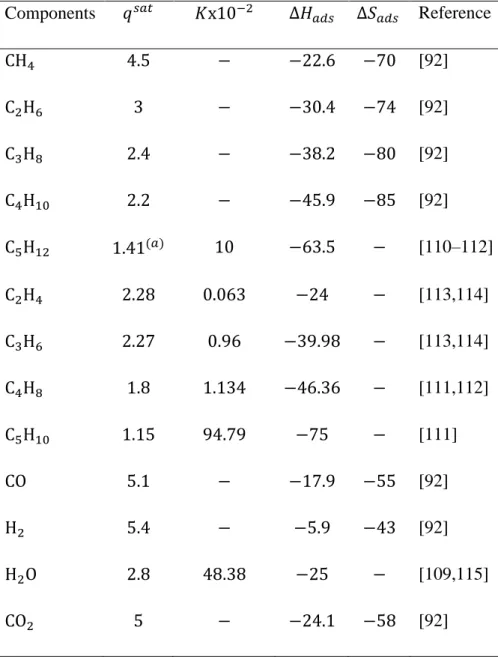
𝑞𝜉𝑠𝑎𝑡 Saturation amount adsorbed of component 𝜉(mol kg−1)
𝑞𝑖 Amount adsorbed of component 𝑖 (mol kg−1)
𝑞𝑖𝑠𝑎𝑡 Saturation amount adsorbed of component 𝑖 (mol kg−1)
𝑅 Universal gas constant (8.314 J mol−1K−1)
𝑅𝑗 Rate of reaction𝑗 (mol kg−1s−1)
viii
𝑅𝐶𝑛𝐻2𝑛 Olefin reaction rate (mol kg−1s−1)
𝑅𝑊𝐺𝑆 Water-gas shift reaction rate (mol kg−1s−1)
𝑆𝑖 Hydrocarbonsselectivity (%)
𝑇 Temperature (K)
𝑇𝑠ℎ Shell temperature (K)
𝑇𝑟𝑒𝑓 Reference temperature (K)
𝑈𝑠ℎ Heat transfer coefficient shell-gases (W m−2 K−1)
𝜈 Gas linear velocity (m s−1)
𝑥 Membrane coordinate
𝑦 Molar fraction
𝑧 Axial reactor coordinate
𝑐 Probability of diffusion in the right direction
Greek letters
𝜀 Porosity of catalytic bed
𝜀𝑚 Porosity of membrane-support layer
𝜌 Catalyst density(kg m−3)
𝜌𝑔 Gas density (kg m−3)
𝜌𝑚 Membrane density (kg m−3)
𝜐𝑖𝑗 Stoichiometric coefficient of hydrocarbon 𝑖 in reaction 𝑗
𝜇 Gas dynamic viscosity (bar s)
𝛿 Membrane thickness (m)
𝜆 Diffusional length (m)
𝜃𝜉 Fractional sites occupancy for component 𝜉
𝜃𝑖 Fractional sites occupancy for component 𝑖
ix ∆𝐻𝑎𝑑𝑠,𝜉 Adsorption enthalpy of component 𝜉 (J mol−1)
∆𝐻𝑎𝑑𝑠,𝑖 Adsorption enthalpy of component 𝑖 (𝑘J mol−1)
∆𝑆𝑎𝑑𝑠,𝑖 Adsorption entropy of component 𝑖 (𝑘J mol−1)
Subscripts
𝑔 Gas-phase
𝑖 Index indicating FT components
𝐼𝑁 Inert gases
𝑗 Index indicating reactions
𝑚 Membrane
𝑛 Chain length of hydrocarbons
0 Inlet reactor Abbreviations 𝐵𝑇𝐿 Biomass To Liquid 𝐶𝑇𝐿 Coal To Liquid 𝐶𝑅 Conventional reactor 𝐹𝑇 Fischer-Tropsch 𝐺𝑇𝐿 Gas To Liquid 𝐺𝐷 Gaseous diffusion 𝐻𝐶 Hydrocarbons
𝑀𝑅𝐶 Membrane reactor for carbon dioxide removal
𝑀𝑅𝑊 Membrane reactor for water removal
𝑃𝐹 Permeation factor
𝑆𝐷 Surface diffusion
𝑆𝑃 Selective permeation
x
Table of Contents
Abstract ... i
Acknowledgments ... iii
List of Papers ... iv
Nomenclature ... v
Lites of Figures ... xii
Liste of Tables ... xiv
General Introduction ...
1CHAPTER I: General Concept of Fischer-Tropsch Synthesis
I.1. General considerations on Fischer-Tropsch synthesis ... 4I.2. Fischer-Tropsch reaction kinetics and micro-kinetics ... 8
I.2.1. Iron catalysts ... 12
I.2.2. Cobalt catalysts ... 17
I.3. Reactors used in FT ... 21
I.3.1. Fixed bed reactor... 21
I.3.2. Fluidized bed reactor... 26
I.3.3. Slurry bubble column reactor... 28
I.3.4. Membrane reactor ... 32
xi
CHAPTER II: Membrane Reactor Simulation Model
II.1. Concept of membrane reactor for ideal permeselectivity ... 36
II.1.1. Simulation concept ... 36
II.1.2. Membrane reactor description ... 38
II.1.3. Reactor model ... 41
II.1.4. Kinetic model ... 44
II.1.5. Permeation model ... 46
II.2. Concept of membrane reactor for non-ideal CO2 permeselectivity ... 50
CHAPTER III: Control of Hydrocarbons Distribution Using Membrane Reactor III.1. In-situ H2O and CO2 removal ... 56
III.2. Effect of permeation on hydrocarbons distribution ... 56
III.2.1. Inlet H2/CO ratio alternation ... 57
III.2.2. Inert gas fraction alternation ... 65
CHAPTER IV: Effect of Non-ideal Permeselectivity on Hydrocarbons
Distribution
IV.1. Diffusion process ... 70VI.2. Predominant mechanism under FT reaction conditions ... 71
IV.3. Pressure effect on CO2 permeselectivity ... 73
xii
Lites of Figures
Figure I.1: reactions scheme for FT synthesis ... 4
Figure I.2: Mechanisms of FT synthesis: (a) CH2 insertion, (b) CO2 insertion, (c) enol ... 11
Figure I.3: Concentration and temperature profile in multi-tubular Fischer-Tropsch reactor ... 24
Figure I.4: multitubular fixed bed reactor ... 25
Figure I.5: (a) Circulating fluidized bed reactor, (b) fixed Fluidized bed reactor ... 27
Figure I.6: FT slurry bubble column reactor ... 29
Figure I.7: Homogeneous and churn-turbulent regime in a slurry bubble column reactor . ... 31
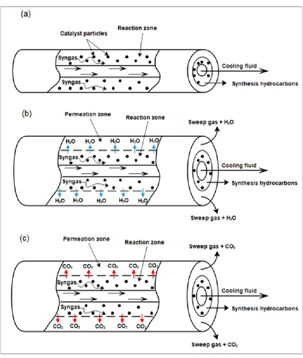
Figure II.1: Schematic diagram of FT membrane reactor, (a): Conventional reactor (CR), (b): Membrane reactor for water removal (MRW), (c): Membrane reactor for CO2 removal (MRC). ... 40
Figure II.2: Scheme of the FT membrane reactor ... 52
Figure III.1: Effect of the inlet H2/CO ratio on hydrocarbons selectivity a: (H2/CO)0=1, b: (H2/CO)0=1.5, c: (H2/CO)0=2 and d: (H2/CO)0=2.5. Conditions: T= 533K, P=20bar and GHSV= 4000h-1 ... 61
Figure III.2: WGS reaction rates evolution in the reactors configurations a:(H2/CO)0=1, b:(H2/CO)0=2.5. Conditions: T= 533K, P=20bar and GHSV= 4000h-1 ... 62
Figure III.3: Evolution of H2/CO ratio along the reactor at different initial values a: (H2/CO)0=1, b: (H2/CO)0=1.5, c: (H2/CO)0=2 and d: (H2/CO)0=2.5 Conditions: T= 533K, P=20bar and GHSV= 4000h-1 ... 64
xiii Figure III.4: Effect of the inert gas fraction in the permeate side on hydrocarbons selectivity for different 𝐼𝑖𝑛𝑑𝑒𝑥. a: 𝐼𝑖𝑛𝑑𝑒𝑥 = 3, b: 𝐼𝑖𝑛𝑑𝑒𝑥 = 6, c: 𝐼𝑖𝑛𝑑𝑒𝑥 = 9, d:
𝐼𝑖𝑛𝑑𝑒𝑥 = 12. Conditions: (H2/CO)0=2.5, T=533 K, P= 20bar, GHSV=4000h-1 ... 66
Figure III.5: Effect of the inert gas fraction on the permeation flux of carbon dioxide
(a) and water (b). Conditions: T= 533K, P=20bar and GHSV= 4000h-1. ... 68
Figure III.6: Evolution of H2/CO ratio along the reactor for different 𝐼𝑖𝑛𝑑𝑒𝑥 a:
𝐼𝑖𝑛𝑑𝑒𝑥 = 3, b: 𝐼𝑖𝑛𝑑𝑒𝑥 = 6, c: 𝐼𝑖𝑛𝑑𝑒𝑥 = 9 and d: 𝐼𝑖𝑛𝑑𝑒𝑥 = 12 Conditions: T= 533K,
P=20bar and GHSV= 4000h-1. ... 68
Figure IV.1: Contribution of surface diffusion (SD) and gaseous diffusion (GD) on the total permeation under simultaneous variation of initial temperature and total pressure. ... 73 Figure IV.2: Evolution of reaction flux (solid), permeate flux (dash) and residual flux (dot) along the reactor at an initial pressure of 11bar. ... 75 Figure IV.3: Evolution of reaction flux (solid), permeate flux (dash) and residual flux (dot) along the reactor at an initial pressure of 14bar. ... 79 Figure IV.4: Evolution of reaction flux (solid), permeate flux (dash) and residual flux (dot) along the reactor at an initial pressure of 17bar. ... 80 Figure IV.5: Evolution of reaction flux (solid), permeate flux (dash) and residual flux (dot) along the reactor at an initial pressure of 20bar. ... 82 Figure IV.6: Variation of the permeation factor as a function of initial pressure. ... 84
Figure IV.7: Variation of the CO2 selective permeation as a function of initial pressure.
xiv
Liste of Tables
Table I.1: Micro-kinetic expression For methane on iron and cobalt catalysts. ... 20
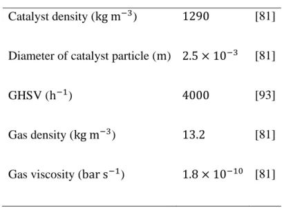
Table II.1: Catalyst and gas proprieties. ... 37
Table II.2: Reactor dimensions and operating conditions. ... 38
Table II.3: Kinetic constants and activation energy for FT and WGS reactions. ... 45
Table II.4: Water and carbon dioxide adsorption and diffusion parameters. ... 50
Table II.5: Adsorption parameters for the permeates. ... 54
Table II.6: Diffusion parameters of permeate species... 55
Table III.1: Measured O/P ratios in the reactor exit for different (H2/CO)0 ratios. ... 65
Table III.2: Measured O/P ratios in the reactor exit for different fractions of inert gas (𝐼𝑖𝑛𝑑𝑒𝑥). ... 69
1 Currently, a promising topic in the energy industry is the obtention of environmentally clean fuels from the transformation of remote abundant sources. The Fischer-Tropsch (FT) synthesis can convert synthesis gas into a multicomponent mixture of predominantly
hydrocarbons. Synthesis gas, a mixture of predominantly CO and H2, obtained from either
coal, biomass or natural gas. Fuels produced with the FT process are of a high quality due to very low aromaticity and absence of sulfur. These fuels are valuable for further industrial transformation such as blending stocks for transportation fuels derived from crude oil or directly used as an upgraded combination of low cost and effective source of energy that respond to the environmental policies. This technology can deliver a direct control of hydrocarbons composition, which constitutes another benefit to achieve the desired distribution of paraffin and olefins. This involves a deep optimization of reactor
parameters such as the inlet H2/CO molar ratio, the nature of the used catalyst, and the
running temperature. In this context, the increase in the H2/CO ratio will favor the
production of paraffin. The partial pressure of carbon monoxide and hydrogen can be managed by water elimination, whereas the equilibrium of the secondary water gas shift
(WGS) reaction shifted toward the formation of reactants (CO+H2O) or products
(H2+CO2).
A critical literature review on the general concept of FT synthesis, the kinetic mechanisms and models and the applied industrial configuration of reactors is given in Chapter I. The kinetic mechanisms for CO consumption to hydrocarbons present some uncertainties and do not fully provide a uniform picture of hydrocarbons distribution. Most of the devoted works on FT kinetic are aiming to better understand the reaction mechanism under a restricted range of conditions. Many authors derived Langmuir-Hinshelwood-Hougen-Watson (LHHW) or Eley-Rideal type of rate expressions for
2 reactant consumption. In most cases, the formation of the building block or monomer, methylene, is assumed to be the rate-determining step. Due to now, none of the available literature models can fully describe the reaction pathway and obtains enough details to predict the product spectrum as a function of operating conditions.
For performing the theoretical investigation of ideal and non-ideal permeation effect on hydrocarbons distribution, a new membrane reactor configuration that deals with water separation or carbon dioxide separation from the reaction zone is proposed in Chapter II. The procedure of analysis is based on building a mathematical model with MATLAB software that can describe the variation of hydrocarbons selectivities at the reactor outlet associated with separate integration of permeselctive membranes to carbon dioxide and water.
Chapter III discusses the proven possibility of applying a new concept of the FT reactor to ensure a more flexible and readily way of controlling and managing the main distribution of hydrocarbons. The particular enhancement of the production yield of desirable product composition can be granted by integrating a tubular membrane to the conventional fixed-bed reactor. The developed configuration will give a big dash to the industry of FT synthesis as valuable production is needed to cover the additional cost of process installation and operation and thus achieving a higher profit rate. The findings were reviewed and compared to the case where the configuration of a conventional fixed bed reactor is applied. Further investigation is done by quantifying the effect of specific
operating parameters such as inlet molar ratio (H2/CO) and inert gas fraction on the
distribution of final products. The results of this study will help with structuring the orientation of hydrocarbons composition as a function of the corresponding equilibrium
3 of the water gas shift reaction. This includes the impact of in-situ water and carbon
dioxide separation on the evolution of the H2/CO ratio and water gas shift reaction rate.
In the previous chapter, the permeation through the silicalite-1 membrane is considered only to carbon dioxide, therefore, assuming other components diffusion is required for the generalization of the model. Non-ideal carbon dioxide permeselectivity is investigated in Chapter IV. Up to now, few works deal with the permeation of wide range hydrocarbons and syngas through silicalite-1 type membranes. Some literature works suggest that the permeation model of the investigated range of hydrocarbons and other gases can be described by a combination of surface diffusion and gaseous diffusion. At now day, the available information does not cover high processing pressures, at which is operated FT synthesis. To be able to predict the permeation effect of such components, a deep investigation of membrane permeselectivity is required. To do this, a variation of total permeation as a function of the initial pressure and temperature is studied for two separate models: surface diffusion and gaseous diffusion. The model which has a major attribution to the permeation process is used for a comparative investigation of different components permeance and pressure effect on the membrane efficiency and the selective
separation of CO2. Also, the consideration of the permeation process can deliver a
significant accuracy about reactor performance and the tendency of hydrocarbons composition. So, the outlet olefin to paraffin ratio is recommended to confirm the real magnitude of the assumption of negligible permeation of hydrocarbons, and its impact on the final distribution.
CHAPTER I
4 I.1. General considerations on Fischer-Tropsch synthesis
Fischer-Tropsch synthesis is defined as an alternative technology that can cover the sharp depletion in the reserve of traditional fossil fuels [1,2]. For the last decades, it is known as the most promising way to reduce the dependency of the industry on the uncontrollable and large fluctuation in the price of drilled oil. This may present a perfect representation of the economic situation worldwide and remote the production of a wide range of hydrocarbons with higher quality and minimal impact on the environment [3]. This configuration can deliver a selective formation of wax materials and even an accountable portion of oxygenates (Figure I.1). By using abundant resources such as coal and biomass, the benefit will be very higher and this may attract more companies to invest in the predominant production of syngas for further application as feedstock to the FT process. The main technologies used for converting natural gas, coal and biomass are known as gas to liquid (GTL), coal to liquid (CTL) and biomass to liquid (BTL), respectively [4].
Figure I.1: reactions scheme for FT synthesis [5].
The principle of transformation is based on the gasification of biomass to syngas or either partial oxidation and steam reforming of natural gas and coal [6]. The biomass feedstock fr gasification process is composed of different biomass heavy dry residues such as straw,
5 energy crops [7]. The main set of FT synthesis is classified as desirable and undesirable reactions, where the formation of paraffin and olefins is considered to be the selective interaction on the catalyst surface. It consists of CO hydrogenation to a wide range of hydrocarbons (HC) and water (Eq.I.1 and I.2).
For paraffin formation:
𝑛𝐶𝑂 + (2𝑛 + 1)𝐻2 → 𝐶𝑛𝐻2𝑛+2+ 𝑛𝐻2𝑂 (I.1)
For olefins formation:
𝑛𝐶𝑂 + 2𝑛𝐻2 → 𝐶𝑛𝐻2𝑛+ 𝑛𝐻2𝑂 (I.2)
As a side reaction, the formed water during the production of hydrocarbons will react with adsorbed carbon monoxide to generate carbon dioxide and hydrogen species. This will increase the molar ratio of syngas and consequently a change in the distribution of hydrocarbons. Also, this reaction is considered as a secondary parasite step, in which the formation of carbon dioxide will harm the environment and reduce the activity of the catalyst by noncontrollable occupancy of the active site. This can lead to competitive adsorption between the syngas and the carbon dioxide resulting in a sharp decline in the reaction rate of FT synthesis. After all, this process can claim the advantage of eliminating the produced water from the reaction area to avoid catalyst permanent deactivation. In fact, the iron catalyst is more sensitive to water than the cobalt catalyst and the high
activity of water gas shift reaction (Eq.I.3) on the Fe2O3 phase can prevent catalyst
poisoning through the oxidation process. Furthermore, the feed composition of syngas must be clan from any metallic effluents especially plomb that can change the catalyst structure by forming a bond with reducted iron sites Fe-Pb. On the other hand, cobalt
6 catalyst has a more stable form but this is not a full indication that is not exposed to the possible oxidation caused by the presence of water. However, there are some studies reported a positive effect of water formation on the reaction rate of FT reaction over cobalt catalysts. This abnormal trend is not completely understood and according to other studies, a nonactive spinal phase is formed on the surface of the cobalt catalyst due to the assisted oxidation by water. For this purpose, the partial pressure ratio of water over
hydrogen 𝑃𝐻2𝑂⁄𝑃𝐻2must be maintained lower than a specific threshold equal to 0,6. CoO
and Co3O4 are the general forms for cobalt deactivation under FT operating conditions.
The production of hydrocarbons is followed by side formation of oxygenates such as alcohol, ketones organic acids with minor quantity (Eq.I.4).
𝐶𝑂 + 𝐻2𝑂 ↔ 𝐻2+ 𝐶𝑂2 (I.3)
𝑛𝐶𝑂 + 2𝑛𝐻2 → 𝐶𝑛𝐻2𝑛𝑂 + (𝑛 − 1)𝐻2𝑂 (I.4)
FT process involves three main units including syngas production through usual resources conversion, feedstock pretreatment and FT synthesis. The FT section constitutes higher interest and it is basically composed of a large-scale reactor, syngas purification from carbon monoxide and a compression unit for recycling the unconverted part of the final products. However, operating at high selective distribution requires additional parametrization of the gasification unit, in which the syngas molar ratio is adjusted according to the drawn plans for FT cuts. In general, the syngas produced from biomass has much higher carbon monoxide content compared to hydrogen. This is not seen for natural gas transformation because of the low molecular weight of reactants. A predefinition of syngas composition is also important to determine the appropriate catalyst for the conversion. In contrast to iron, cobalt catalyst activity is restricted to a
7
narrow range of variation in the molar ratio of the syngas H2/CO [8,9]. As we discussed
above, the water gas shift reaction can alter the composition of syngas towards an increase in the molar ratio. This is can be beneficial for both industrial types of catalysts, but with a higher specification to cobalt, in which more hydrogen content is required. Chemical and physical promoters are usually blended to the iron catalyst in order to increase its activity to FT reaction and enhance the selectivity towards the production of heavier hydrocarbons [10–12]. For cobalt the addition of promoters can elevate more the cost of the catalyst and thus increasing the exposition of the active phase on the surface of the catalyst will generate a large area of contact with just using support materials either than promoters [13,14]. After hydrocarbons production, a large set of the conventional refining process is used to enhance the quality of products and gaining some advantages through multiple transformations of crude oil to more valuable cuts that can be sold directly for further treatment or delivered to associated units for general purposes. From a general perspective, the fuels produced by FT synthesis are clean of nocive material to the environment such as benzene and sulfur [15,16]. In fact, the emission of carbon dioxide can also be reduced to a factor of 15% through the combustion of synthesis fuels [17]. This will reduce the need for treatment steps and address any problem related to the presence of these undesirable components in the conventional type of fuels. Actually, the produced diesel by FT synthesis has a high cetane number resulting in better ignition properties. In general, the acceptable cetane number for commercial diesel is about 55 which is much less than the offered number by synthesis diesel (70). The diesel obtained from BTL can be borderline competitive to the derived diesel from crude oil at a large scale of comparison including the price and the quality [18]. Also, BTL can offer
high-8 quality jet fuel compared to the conventional one which requires additional treatment for certified use.
I.2. Fischer-Tropsch reaction kinetics and micro-kinetics
Considerable researches were devoted to developing a more comprehensive mechanistic scheme for describing the reaction at the microscopic level [19–21]. The kinetic of FT is referred to be general when the representative model does not scoop the variation of product distribution. This kind of kinetic can be used only to oversimplify the evolution of syngas conversion and it is based on empirical correlations that describe the total variation in reaction rate related to syngas consumption [22]. The reaction rate of FT synthesis is expressed by power-law kinetics derived from Langmuir-Hieshelwood-Hougen-Watson (LHHW) and Rideal mechanisms [23,24]. Different theoretical sets of elementary reactions were builts to predict the reaction pathway on the catalyst surface. Most of these kinetics expressions fit with the experimental investigations at a narrow range of reaction conditions [25]. However, the weak interaction between the syngas and the catalyst surface will result in lower occupancy. This behavior constitutes a major concept of the applied Eley-Redial model. The LHHW kinetic expression is mainly taken for describing the whole process by only one rate-determining step via either the monomer formation or reaction termination [26]. The elementary reactions are defined by bonding formation with active sites or other molecules [27]. Anywhere, the contribution of a large number of products that are engaged in the FT reaction to the reaction rate must not be neglected for the sake of reducing the size of the investigation. This may create a non based explanation of observed alteration in the final distribution of products. Anderson Schulz Flory (ASF) model is well known as a complete model that can predict the distribution of hydrocarbons. According to the ASF model, the final
9 composition of hydrocarbons is determined by the spatial architecture that surrounds the active site of chain growth [28]. The change in the selectivity of hydrocarbons is related to the rate of desorption at which methyl addition can be substituted by hydrogen or double bond formation for producing paraffin or olefins, respectively. In general, the desorption probability of olefins is quite higher than that of paraffin because the desorption of paraffin is more likely to be inhibited by the propagation process. But for
instance, any change in the spatial constraints by raising the feed molar ratio H2/CO can
provoke competitive adsorption on the surface of the catalyst and thus unexpected tendency towards the formation of saturated hydrocarbons will take place. But this model assumes a linear distribution of hydrocarbons along the chain length, for instance, the production yield of ethane is regressive to the production yield methane. This model is weak for predicting the real distribution, which lies in the changes that can be generated through the variation in the surface coverage or the catalyst activity. However, the ASF model implies that less selective production is obtained for long hydrocarbons chains. In other words, the desorption rate of hydrocarbons decreases along with the carbon number. By assuming constant chain growth probability, the ASF model does not predict the influence of products on final distribution [22]. For this purpose, a detailed kinetic model came to the surface to deal with integrating a logical construction that can describe all possible deviation through a separate prediction of hydrocarbons distribution. In general, the micro-kinetic model of the FT reaction is essential for the prediction of the real reaction pathway that can be executed consistently to match the obtained conversion of syngas and hydrocarbons selectivity. However, These detailed kinetic models were developed by applying different mechanisms that were proposed to present an accurate evolution of product distribution. Far away, three mechanisms have been widely
10
accepted. This includes CH2 insertion, CO insertion and enol mechanisms (Figure I.2).
There is a sequence in the intermediate reactions that lie mainly on hydrogen dissociative adsorption followed by a combination with the adsorbed molecules of carbon monoxide. Based on the way of which hydrogen will react with carbon monoxide, two plausible interactions can be wrapped up including hydrogen bonding with carbon after carbon monoxide dissociation or direct insertion of hydrogen on the nondissociated carbon
monoxide. The first approach conducts to the direct formation of CH2 intermediates as
known by the carbide mechanism, where hydrocarbons are built through the successive
insertion of hydrogen on the formed phase with carbon atom (Fe3C5) [27]. The originality
of this proposed mechanism back to Fischer and Tropsch, in which they have implied that
hydrocarbons chains growth is granted through the successive addition of CH2 formed on
the catalyst surface to the adsorbed R-C radicals [22,28]. This mechanism can generate linear alkanes, linear alkenes and branched 1-alkenes through three estimated reaction pathways [22]. This theory was primarily discarded due to the nonexistence of the carbide phase on the surface of cobalt and nickel catalysts [28]. Anywhere, updated researches on the predicted model have proven through the utilization of spectroscopic methods the reactivity of carbon with hydrogen for the formation of methyl intermediates [22]. Isotropic-tracer techniques are used to identify the presence of methyl on the surface of
the Fe/Al2O3 catalyst [29]. Also, the activation of CO dissociation by hydrogen assistance
has prevailed CH2 insertion mechanism to be valid on cobalt [22]. A recent study has
shown that the direct carbon monoxide dissociation is expected to be more difficult than H-assisted carbon monoxide dissociation [30]. Storch and his team are the first who proposed a mechanism that is based on this approach for the apparent explanation of oxygenates formation during FT synthesis [28]. However, even there are fewer shreds of
11 evidence on the formation of a carbonic surface on cobalt its seems that the reaction pathways follow the carbide mechanism. The carbide mechanism is more appropriate for describing the micro-kinetic of FT synthesis.
Figure I.2: Mechanisms of FT synthesis: (a) CH2 insertion, (b) CO2 insertion, (c) enol
12 The CO insertion mechanism is also used to describe the formation of oxymethylene on the catalyst surface. The enol mechanism is still not ruled because of the contradiction that was found during the experiment of injecting alcohol with syngas as a feed mixture. The results indicate that the alcohol was clung to the propagated hydrocarbons chain by the liberation of oxygen molecules instead of reacting with adsorbed carbon monoxide [28]. Thus, the postulated carbon monoxide insertion is not supported to describe the pathway of the FT reaction. A wide range of transition metals was tested on the FT reaction. But only cobalt and iron catalysts were commercialized since Rh, Ir, and Pt metals have poor catalytic activity, Ni generates excessive production of methane and Ru is too expensive [13,18,22,31]. Ideally, reaction conditions, as well as catalyst type, determine the convenient combination of the reaction rate. Kinetic models of iron and cobalt catalysts will be be reviewed in more detail. The rate-determining step can be attached to carbon monoxide consumption or reaction termination through hydrocarbon desorption.
I.2.1. Iron catalysts
The iron catalyst was the first material tested on FT synthesis [28]. The cost of iron-based FT catalyst is lower than that of cobalt and it was estimated at the range of 10-40$/bbl [2]. In contract to cobalt, the activity of iron catalysts towards the production of light hydrocarbons is less influenced by temperature gradient. Even at high operating temperatures the selective synthesis of heavy hydrocarbons still favored [28]. In most cases, the alkali promoters are added to the active phase to enrich the acidic character of the catalytic surface by chemical structuration or physical dispersion of the phase on the support. In reality, the production of light or heavy hydrocarbons can be directed through the applied method for iron preparation [28]. We can distinguish that the reduction of
13 natural magnetite can result in high production of gases while a synthetic method using precipitation of iron sales leads to a more accurate selection of the liquid phase. Along with that, it can be said that the second method is favored regarding the goals of FT synthesis for large production of useful petroleum cuts such as gasoline and diesel. A set of reaction rates for iron catalyst were reviewed by Lox and Froment [27] and Van der Laan and Bennackers [26]. At low conversions, the reaction rate is reported to be expressed in terms of the first-order power-law expression dependency where carbon monoxide partial pressure has no contribution to the reaction rate [6,7]. In his study, Anderson found that the inhibition effect of formed water must be included for higher operating temperatures and syngas conversion (60%). Here, site occupancy is considered and assumed to be strongly defined by carbon monoxide and water adsorption [32]:
𝑅𝐹𝑇 = 𝑘0𝑃𝐶𝑂𝑃𝐻2
𝑃𝐶𝑂+𝑎𝑃𝐻2𝑂 (I.5)
Dry has explored this effect by using the carbonyl mechanism as a derivative source beyond the strong formation of water molecules [33]. His incorporation of the Langmuir-Hinshelhood-Hougen-Waston (LHHW) approach was conducted to the formulation of Anderson’s equation. Huff and Satterfield indicate that the adsorption term 𝑎 depends on syngas composition as it decrease with increasing the partial pressure of hydrogen [34]. Based on this observation he derived another reaction rate equation that describes more accurately the relative variation of adsorption to the presence of hydrogen, where the constant a is substituted by:
𝑎 = 𝑏
14 Several studies reported that the utilization of Huff and Satterfield equation for approaching the experimental results has got a reasonable matching. The calculated activation energy of the FT reaction rate corresponds to the range of expectation (between
71 kJ/mol and 105 kJ/mol) [34–39]. Inhibition by CO2 is generally not considered to be
applied to the general law because of its low adsorption on the catalyst surface [36,40]. But the effect may become remarkable when the water gas shift reaction is highly activated by increasing the operating temperature [41]. This reaction will produce a large
amount of CO2 that provokes a reduction in the number of active sites through the
adsorption process. Consequently, a decline in the FT reaction rate is expected to happen. A similar equation to that used on water inhibition was proposed for incorporating the
CO2 effect:
𝑅𝐹𝑇 = 𝑘0𝑃𝐶𝑂𝑃𝐻2
𝑃𝐶𝑂+𝑎𝑃𝐶𝑂2 (I.7)
A general kinetic model was developed to consider the difference in generated effect by water gas shift reaction activity [41]:
𝑅𝐹𝑇 = 𝑘0𝑃𝐶𝑂𝑃𝐻2
𝑃𝐶𝑂+𝑎𝑃𝐻2+𝑏𝑃𝐶𝑂2 (I.8)
All the discussed kinetics were assumed to be valid only if we define the elementary reaction of hydrogen with carbon atoms as a rate-determining step, while all other steps are considered to be at a quasi-equilibrium state [26,42]. As we mentioned in the above section, this kind of kinetic model can not fully characterize the evolution of product formations along the reactor section and does not reply to the intense needs of constructing a deep knowledge about FT kinetic for sharp prediction of selectivities. Some works reported the successful application of power-law expressions in describing
15 the production rate of hydrocarbons as a function of the partial pressure of carbon monoxide and hydrogen [1,25]:
𝑅𝐻𝐶 = 𝑘𝐻𝐶𝑃𝐶𝑂𝑚𝑃
𝐻2
𝑛 (I.9)
The model was applied on a specific range of hydrocarbons including CH4, C2H4, C2H6,
C3H8, n-C4H10, i-C4H10 and C5+ paraffin. According to Rahmati's findings, the power of
partial pressure of CO is negative for methane and ethane which indicates the low formation of light paraffin at a higher injection flow rate of carbon monoxide [25]. This is in agreement with what was reported by other studies using a distinct form of kinetics. The estimation rate of hydrocarbons by applying empirical correlations of power-aw kinetic has let to good results [43]. For higher chain length the power of carbon monoxide partial pressure increases and thus resulting in less dependency of hydrocarbons formation on hydrogen partial pressure. Mazzone and Fernandes used a polymerization model to define the mass balance for the formed hydrocarbons by assuming that alkyl and alkenyl mechanisms are both acting in FT synthesis [44,45]. A reaction path based on CO consumption to the formation of methyl on the surface of the precipitated iron catalyst
(Fe-Cu-K-SiO2) was used to develop a distinct set of kinetic models [26]. Carbide and
enol mechanisms can be perfectly applied to represent the experimental results, where the best model showed that the hydrogen association to nondissociative carbon monoxide is highly recommended to be the rate-determining step. Even old investigation has proven the dissociative adsorption of CO on the iron catalyst through the application of spectroscopic techniques, there is still no clear evidence for the relative rate of carbide formation [46,47]. This can be explained by the diversity in the structure of carbide along with the surface plan of iron [48]. Theoretical investigation of the iron model carried out using DFT calculations has shown that the minimum energy paths are consistent with
H-16 assisted CO dissociation [49]. Furthermore, Lox and Froment reported that the variation in the partial pressure of hydrogen and carbon monoxide affect similarly the initial pressure of paraffins and olefins. This implicit the formation of paraffin and olefins chains along parallel reaction paths [27]. The formation of hydrocarbons on iron catalysts using carbide mechanisms can be summarized in five essential steps [27]:
• The molecular adsorption of carbon monoxide • Dissociative adsorption of hydrogen
• Methyl intermediate formation
• Propagation of hydrocarbons building block • Desorption of hydrocarbons products
The rate equation is developed by applying some assumptions related to the adsorption mechanism. The accuracy of the Langmuir-Freundlich-Hinshelwood model in describing FT synthesis was investigated in a slurry phase bubble column reactor over a wide range of conditions, the results are in very good matching with the experiment [50]. ASF model with two chain growth probability was first proposed by Donnelyet al [51] and it is widely used to describe the observed deviation in the basic model. A study has reported the higher accuracy of the model compared to the experimental results. Also, this model can provide a good interpretation of the non-linear distribution of hydrocarbons. As indicated by the theoretical model, the low apparition of heavy olefins on the FTS hydrocarbons spectrum is a result of the high activation energy [52]. Also, the production rate of hydrocarbons can be described by using fundamental assumptions such as steady-state kinetic [53,54]. By assuming a detailed scheme for the elementary reactions, many researchers were able to derive a complete mechanistic model from polymerization kinetic. Here, the rate of paraffin desorption by hydrogenation is equal to the rate of
17 methyl intermediate formation [55]. Also, the rate constant is dependent on the chain length at lower molecular weight including the desorption reaction for methane, propane. In general, the formation of hydrocarbons is related to the distribution of adsorbed species on active sites, for instance, paraffin is produced through the reactivity of alkyl chain with the nearby site that carries the monomer and another contains the hydrogen atom for termination reaction. Only limited number of kinetics predict the formation of oxygenates, a study done by Christophe [56] that considers two assumptions where non-dissociative adsorption of carbon monoxide is used for describing the formation of hydrocarbons and global stoichiometric reaction model is applied for defining the formation of alcohol over a precipitated iron catalyst in slurry bubble column reactor [56]. However, secondary reactions such as olefins readsorption were proven to have a higher tendency to occur during FT synthesis. The possibility of getting a secondary reaction of olefins is proposed to be held on a separate hydrogenation site [36]. The developed models show a decrease in olefins to paraffin ratio upon the increase in chain growth. This decrease in olefins content was explained by the excessive readsorption of olefins. However, FTS and WGS reactions are generated on different kinds of active sites and the interaction between these two reactions is ensured via the gas phase [52]. Separate expressions are used to describe the mechanism of the WGS reaction.
I.2.2. Cobalt catalysts
Cobalt has low selectivity towards the formation of oxygenates [22]. This property represents a benefit to the FT industry where a low generation of oxygenic compounds is needed to be established for achieving high production profit. ASF approach for FT reaction rates has shown a linear tendency, except for methane where positive deviation in the chain length probability has been remarked due to the methanation reactions that
18 are favored over the cobalt catalyst [57]. The readsorption reactions of olefins are also considered by many kinetic approaching types of research [28]. FT synthesis aims to ensure a large production of long hydrocarbons chain length [28]. As a solution for
maintaining the formation of methane, a low H2/CO molar ratio must be put to avoid the
valueless light distribution of fuel while heavier compounds are desirable for commercial and energetic benefits [9,28]. In fact, the large diffusion of hydrogen through the cobalt pores will constitute a barrier or as it is called ‘egg-shell’ that prevents the insertion of methyl intermediates [28]. Also, methane selectivity is highly sensitive to the operational parameters, since the increase in FT temperature can boost its formation. In general, a narrow range of pressure and temperature variation was applied to FT reaction over the cobalt catalyst for limiting the production of light hydrocarbons [13]. Only a few kinetic studies on cobalt catalysts are reported in the literature. The developed kinetics are quite different from that of iron catalyst. It can be noted that theses kinetic expressions include a dual-site surface reaction of the rate-determining step [26]. The inhibition of water is
not expressed for cobalt catalysts as well as the inhibition of CO2 due to less activity of
water gas shift reaction [26]. A study shows that methyl formation via the H-assisted CO dissociation is more consistent for describing the FT mechanism on cobalt [49]. Several developed models for expressing the general reaction rate are based on carbide mechanisms and enol/carbide combination mechanism [54]. This involves two rate-determining steps including dissociative adsorption of hydrogen on cobalt surface and carbon intermediate formation. Assuming other elementary reactions as a determining step has conducted to new forms of kinetic models. However, the generated models by considering carbon monoxide hydrogenation resulted in large variance with respect to the experiments. An experiment was carried out in a slurry reactor has delivered a well fitting
19 of kinetic measurements with Langmuir-Hinshlwood model for the bimolecular surface reaction [58]:
𝑅𝐹𝑇 = 𝑘𝑃𝐶𝑂𝑃𝐻2
(1+𝐾1𝑃𝐶𝑂)2 (I.10)
Literature investigations have correlated the rate of syngas consumption to the kinetics used on the iron catalyst and the best fit was achieved [59]. In comparison to iron, FT kinetic over cobalt is not associated with the formation of water and carbon dioxide and is controlled through one type of catalytic site. Detailed LHHW equations that describe the reaction rate are widely accepted models for approaching a good representation of the production rate of hydrocarbons. Similarly to the iron catalyst, the secondary reaction was also considered as a basis for building the kinetic model. The increase in the reabsorption rate was due to the higher physisorption of longer olefins chains. Besides, the readsorption coefficient of ethene is larger than that of olefins. Lox and Froment developed kinetic models for multiple rate-determining steps including the desorption of products and the adsorption of carbon monoxide [27]. Their prediction for constant olefins to paraffin ratio does not cover the observed deviation in product distribution.
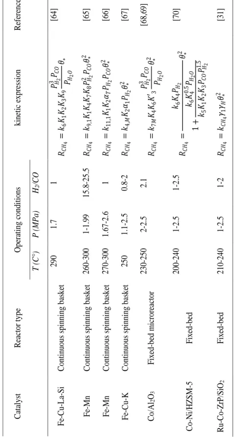
20 C atalyst R ea ctor type Ope ra ti ng c ondit ions kinetic e xpre ssi on R efe re nc e T (C°) P ( M Pa) H2 /C O Fe -Cu -La -Si C onti nuous spi nning ba ske t 290 1.7 1 𝑅𝐶𝐻 4 = 𝑘6 𝐾1 𝐾2 𝐾3 𝐾9 𝑃𝐻2 3 𝑃 𝐶 𝑂 𝑃𝐻2 𝑂 𝜃∗ [64] Fe -Mn C onti nuous spi nning ba ske t 260 -300 1-1.99 15.8 -25.5 𝑅𝐶𝐻 4 = 𝑘9,1 𝐾1 𝐾4 𝐾7 𝐾8 𝑃𝐻2 2 𝑃 𝐶 𝑂 𝜃∗ 2 [65] Fe -Mn C onti nuous sp inni ng ba ske t 270 -300 1.67 -2.6 1 𝑅𝐶𝐻 4 = 𝑘11 ,1 𝐾1 𝐾2 𝛼𝑇 𝑃𝐻2 𝑃𝐶𝑂 𝜃∗ 2 [66] F e-Cu -K C onti nuous spi nning bas ke t 250 1.1 -2.5 0.8 -2 𝑅𝐶𝐻 4 = 𝑘4,𝑀 𝐾2 𝛼1 𝑃𝐻2 𝜃∗ 2 [67] C o/Al 2 O3 F ixed -be d mi cror ea ctor 230 -250 2-2.5 2.1 𝑅𝐶𝐻 4 = 𝑘7𝑀 𝐾4 𝐾6 𝐾 ′3 𝑃𝐻2 3 𝑃 𝐶 𝑂 𝑃𝐻2 𝑂 𝜃∗ 2 [68,6 9] Co -Ni /HZ S M -5 F ixed -b ed 200 -240 1-2.5 1-2.5 𝑅𝐶𝐻 4 = 𝑘6 𝐾4 𝑃𝐻2 1 + 𝑘6 𝐾4 0 .5 𝑃 𝐻2 𝑂 𝑘5 𝐾1 𝐾2 𝐾3 𝑃𝐶𝑂 𝑃𝐻2 1 .5 𝜃∗ 2 [70] Ru -Co -Zr P /S iO 2 F ixed -be d 210 -240 1-2.5 1-2 𝑅𝐶𝐻 4 = 𝑘𝐶𝐻 4 𝛾1 𝛾𝐻 𝜃∗ 2 [31] T ab le I.1: Micr o -k inetic expre ssi on F o r me thane on iron a nd c oba lt c ataly sts .
21 I.3. Reactors used in FT
Commercial FT reactors were developed before and during World War II for increasing the potential production of fuels at large scale. After passing this period, the interest in FT synthesis has declined due to the high cost of process installation and operation. Recently, the conversion of remote natural gas to hydrocarbons has revived the interest in implanting more advanced technologies in the commercialized reactors. This has been conducted to large production capacities with economical benefit. The main type of reactors that are mostly used by the industry of FT synthesis described in the following section. More advanced concepts of reactors belong to the classes of a fixed bed, fluidized bed and slurry reactors.
I.3.1. Fixed bed reactor
A fixed bed reactor is mostly the preferred conception for large scale production of hydrocarbons, where finite specification on the composition purity is not required [67]. For minimizing the pressure drop along the catalytic bed, a large diameter of particles is used for packing the reaction section. This will mainly conduct intraparticle diffusion issues and consequently a sharp reduction in the reaction rate is expected. Considering the low inclusion of the external mass transfer effect, it is proven through the experiment that the deposit of hydrocarbons interior the porous media of particles creates a liquid-film or interface that has resistance to the diffusion of reactants molecules through the active sites. This represents a determining factor in the diffusivity process of hydrogen into filled pores of heavy hydrocarbons [68]. In fact, the intraparticle diffusion starts to take place if the diameter of the catalyst is superior to 0.5 mm. So, this factor plays an impediment role in the modest integration of a fixed bed reactor in the FT industry. The nature of the FT reaction is exothermic isothermal conception is needed for maintaining
22 the initial temperature. By considering these thermic restrictions multi tubes are implanted inside the reactor shell for ensuring desirable convection and therefore flexible control of exothermic FT reactions. Many reactor configurations were put in use for industrial applications. The radial transport of heat can also cause bad distribution problems and poor conductivity of tubes walls can generate some rise in the temperature profile along with the radial dispersion. The presence of temperature fluctuations is hardly seen in the sable operating regions and must be avoided as it can cause a decline in the catalyst performances including selectivity shifting and activity decrease. Besides the choice of reactor diameter, the catalyst particle size and the gas velocity can determine the trend of heat transfer inside the catalytic bed. Research has investigated the relation between heat transport and bulk flow regime, the results indicate that the heat conductivity and the transfer coefficient tends to increase upon Reynolds number raise. This confirms the assumption that higher particle size generates less flow resistance or pressure drop and thus higher fluid velocity is resulted in conducting the heat transfer in both radial and axial directions of reactant flow [68]. This proportionality can be inversed by applying a larger catalyst size. The implantation of a single tubular reactor, in which the cooling fluid circulates inside the catalytic section can guarantee high heat elimination through overall convection of the bulk and thus better control of the reaction conditions [28,69]. A spray of oil is fed to the upper section of the reactor to remove the heat generated by the catalytic reaction and thus achieving better control of temperature [70]. A variety of fixed bed tubular reactors are widely used in the industry of FT, the reactor may constitute of a large-sized tube filled with a set of parallel fine tubes that carry the catalytic bed. The heat transfer is ensured through injecting a cooling fluid water/steam in the outer section of the reaction tubes. Other reactor designs include the arrangement
23 of catalyst particles in a shell system, where the cooling fluid flows in the area inside the tube. This type of reactor is used by the Sasol oil company [70]. Since the heat transfer in the axial direction is relatively low in the case of long tubes are installed, temperature profiles present nonequal distribution of temperature along with the reactor length. The difference in temperature between the bulk region and the walls of the tubes is huge at a large scale of measurement. Figure I.3 shows a strong dependency of temperature on the radial distance at the reactor inlet. This was explained by the high reaction rate due to the important partial pressure of reactants. For longer distances, the radial profile becomes less observable due to the decrease in reaction rates as the reactants are more consumed. It is also relevant that the reactor was designed with an extended variation in the diameter. This is not responding to the suggested requirement for reducing the temperature gradient. To maintain the operating temperature unconverted portion of the feed gas is recycled [70]. Building a higher number of concentric catalytic tubes is beneficial in terms of reducing FT exothermicity but this implies a longer period to operate a replacement of the deactivated catalysts [56]. An adiabatic fixed bed with a single bed is based on circulating the hot fluid in the external cooling system [68]. This type of reactor has a limited scale of conversion with a capacity of 15bbl/day. Also, heat transfer requires large recycling steams and this will result in a higher drop in pressure and intense consumption of energy. These limiting factors let the adiabatic fixed-bed reactor not be considered in further applications for syngas conversion [68]. Multitubular fixed bed reactor with gas recycling has got increasingly interested utilization due to its large scale of treatment of 400bbl/day (Figure I.4). The reaction rate profile along with the reactor length is incredibly higher than that of the nonrecycled reactor and the enhanced flow rate conducts to greater elimination of heat from the circulating fluid.
24 Figure I.3: Concentration and temperature profile in multi-tubular Fischer-Tropsch
reactor [68].
This process was installed by Sasol company at Sasolburg in South Africa [68]. Moreover, the concentration profile is affected by flow resistance in the axial direction, strictly speaking, a small value of conversion can be achieved at the reactor outlet. This is way unconverted fluid is highly recommended to be recycled. To gain some heat transfer in one hand and increase the linear velocity of reactants in the other hand. This combination of temperature control and through gas recycling will lead to higher production capacity, lower cooling area and reasonable reduction in packed catalyst quantity. A multitubular reactor has been applied for the transformation of syngas in heavy and waxy FT hydrocarbons with a special design of catalyst structure and reactor capacity [71]. This has improved the production rate compared to the conventional one with 3000bbl of daily conversion capacity. The high packed amount of catalysts in the
25 multitubular reactor makes it not an attractive process due to the repetitive loading and unloading operations, which require a shut-in production for long period. In contrast to the fluidized bed reactor and slurry bubble column reactor, the multitubular reactor does not need an integrated unit that works on the separation of catalyst from the reaction phase. This part of the process may require advanced technology for ensuring effective filtration of the small part of the catalyst particles that can be generated from the attrition problem. This will affect the estimated benefit and can introduce additional costs to the operating plant. The scaling up for multi-tubular rig is done in an easy manner where the principal in laboratory application is identical to the industrial field.
26 I.3.2. Fluidized bed reactor
FT synthesis is characterized by high exothermicity, which can provoke bad distribution of reaction rate and syngas conversion due to the apparition of hot spots along the catalytic bed. Fluidized bed reactors are known for their smooth elimination of the generated excess in heat through phases mixing. This characteristic has attracted many industries to apply such kinds of reactors. As we discussed above, the fixed bed reactor is performed over large-sized catalysts which results in intraparticle diffusion limitations. By using a Fluidized-bed catalyst lower diffusion limitation is expected because of the small size of catalyst particles (100𝜇𝑚 ). However, the small size of particles can cause a serious problem by creating a possible agglomeration and thus inhibit the flow of fluids. The commercialized fluidized bed reactor is operated at relatively high temperature and moderate pressure, which leads to the large production of light hydrocarbons [68]. In fact, the conditions must be kept as it is otherwise the heavier chain of hydrocarbons will inevitably condensate on the surface of the catalyst and ruling out the possibility of having chain growth probability higher than 0.71. The only chance to have a heavier composition of products is to add a liquid phase to the gas and solid phase in the reaction area. By this attempt, when the temperature reaches the dew point, the hydrocarbons will condensate in the liquid phase rather than coating the catalyst particles. Several studies are devoted to developing the existing versions of circulating fluidized bed reactors [70]. The major problems of fixed fluid bed reactors are inspected to cover the degradation of the catalyst due to attrition as well as the readily decline in the amount of catalyst in the reaction zone [70]. Sasol company was able to adapt the circulating fluid bed reactor to its high-temperature FT plant [70]. A three-phase fluidized bed reactor is referred to as a fluid circulation process in which the catalyst bed is expanded by a concurrent flow of oil and
27 gas [68]. The configured reactor has not been commercialized and the only lab-scale reactor was built and tested [73].
Figure I.5: (a) Circulating fluidized bed reactor, (b) fixed Fluidized bed reactor [5].
A bubbling regime was performed on a fluidized bed reactor for producing gasoline, where the reaction heat is eliminated using immersed bindles of pipings [74]. This process has been constructed in Brownsville but it was abandoned later on due to technical problems [68]. The first commercial version of a fixed fluidized bed reactor has been implemented in Sasolburg [75]. This has got a successful application with regards to the circulating fluid bed scale due to its compact form, less catalytic attrition and readily maintenance. These advantages reduced the operating cost of the process and thus resulting in higher utilization of a fixed fluidized bed reactor was achieved. The reaction rate of FT synthesis is related to catalyst density, for more compact reactors, syngas
![Figure I.1: reactions scheme for FT synthesis [5].](https://thumb-eu.123doks.com/thumbv2/123doknet/3463844.101189/21.892.268.631.691.898/figure-i-reactions-scheme-ft-synthesis.webp)
![Figure I.2: Mechanisms of FT synthesis: (a) CH 2 insertion, (b) CO 2 insertion, (c) enol [22]](https://thumb-eu.123doks.com/thumbv2/123doknet/3463844.101189/28.892.132.744.277.1048/figure-mechanisms-ft-synthesis-ch-insertion-insertion-enol.webp)
![Figure I.4: multitubular fixed bed reactor [72].](https://thumb-eu.123doks.com/thumbv2/123doknet/3463844.101189/42.892.209.694.529.1036/figure-i-multitubular-fixed-bed-reactor.webp)
![Figure I.6: FT slurry bubble column reactor [77].](https://thumb-eu.123doks.com/thumbv2/123doknet/3463844.101189/46.892.195.671.242.709/figure-i-ft-slurry-bubble-column-reactor.webp)
![Figure I.7: Homogeneous and churn-turbulent regime in a slurry bubble column reactor [68]](https://thumb-eu.123doks.com/thumbv2/123doknet/3463844.101189/48.892.226.641.400.925/figure-homogeneous-turbulent-regime-slurry-bubble-column-reactor.webp)
![Table II.3: Kinetic constants and activation energy for FT and WGS reactions [93].](https://thumb-eu.123doks.com/thumbv2/123doknet/3463844.101189/63.892.173.769.119.495/table-ii-kinetic-constants-activation-energy-wgs-reactions.webp)