Pépite | Modélisation du canal de propagation GNSS en milieu contraint : contribution à l’amélioration de la qualité de service de géolocalisation
220
0
0
Texte intégral
(2) Thèse de Ni Zhu, Université de Lille, 2018. © 2018 Tous droits réservés.. lilliad.univ-lille.fr.
(3) Thèse de Ni Zhu, Université de Lille, 2018. GNSS Propagation Channel Modeling in constrained environments: Contribution to the improvement of the geolocation service quality Abstract : From user guidance applications to trains or road vehicles fleet management, Global Navigation Satellite System (GNSS)-based positioning systems are more and more spread and used in urban environments. However, urban environments present great challenges for GNSS positioning since numbers of obstacles result in signal attenuations and blockages, which can cause large errors. Yet, for new GNSS land applications, knowing the certainty of one’s localization is of great importance especially for the liability/safety critical applications such as automated driving, electronic road tolling or railway signaling. The concept of GNSS integrity, which is defined as a measure of trust to be placed in the correctness of the information supplied by the total system, can help to meet this requirement. Although GNSS integrity has been firstly developed and formalized in the aviation field, the algorithms developed for the aerospace domain cannot be introduced directly to the GNSS land applications. This is because a high data redundancy exists in the aviation domain and a basic hypothesis that only one failure occurs at a time is made for aviation schemes, which are not the case for the urban users. It is a great challenge to extend the integrity monitoring algorithms to GNSS urban applications. The main objective of this PhD research work is to improve the performance of GNSS positioning in urban environment, especially the performance of accuracy and integrity. Under this framework, two research directions were investigated: - The first direction of this PhD research mainly consists of GNSS measurement error characterization in order to improve the positioning accuracy in stringent environments. Several error models existed in the literature are investigated and evaluated, for instance the signal carrier-power-to-noise-density ratio (C/N0) dependent variance model, the satellite elevation dependent variance model as well as the Dirichlet Process Mixture (DPM) model. A new hybrid model is proposed while involving the contribution of the digital map to distinguish the signal reception state LOS/NLOS. - The second direction contributes to the Fault Detection and Exclusion (FDE) techniques so as to improve the GNSS integrity performance in urban environments. Different FDE methods, which can be potentially applied on the land GNSS-based applications, are investigated and compared with real GPS data collected in urban canyon. Two classes of FDE strategies are involved: the snapshot Least-Square-Residual (LSR)-based one and the sequential ExtendedKalman-Filter (EKF) innovation-based one. A new method of HPL computation by taking into consideration of the potential prior fault is proposed. Then, these two research directions are combined together and the computation of Horizontal Protection Level (HPL) is added at the next step so that a complete integrity monitoring scheme is constructed. The results with real GPS data collected in urban canyon show that the accuracy and integrity performance of positioning can be improved with the proposed scheme compared to the traditional approaches. The proposed integrity monitoring scheme is promising to be implemented in the lowcost GNSS commercial receivers for urban transport applications. Keywords : GNSS, Integrity monitoring, Fault Detection and Exclusion (FDE), Urban environments.. © 2018 Tous droits réservés.. lilliad.univ-lille.fr.
(4) Thèse de Ni Zhu, Université de Lille, 2018. Modélisation du canal de propagation GNSS en milieu contraint: Contribution à l’amélioration de la qualité de service de géolocalisation Résumé : Au cours des dernières décennies, de plus en plus d’applications de transport urbain basées sur les systèmes de positionnement par satellites (GNSS) ont vu le jour. Des applications exigent une fiabilité critique comme le télépéage basé sur l’utilisation du GNSS, pour lesquelles des erreurs de positionnement peuvent entraîner de graves conséquences. Pourtant, les environnements urbains présentent de grands défis pour le positionnement GNSS en raison de l’existence des trajets multiples et des signaux NLOS (None-Line-of-Sight). Le concept d’intégrité GNSS, qui est défini comme une mesure de confiance qui peut être placée dans l’exactitude des informations fournies par le système de navigation, peut aider à répondre à cette exigence. Bien que l’intégrité GNSS ait d’abord été développée et formalisée dans le domaine de l’aviation, les algorithmes développés pour l’aérospatial ne peuvent pas être introduits directement dans les applications terrestres. Parce qu’il existe une forte redondance des données en ciel dégagé et que l’hypothèse d’une seule défaillance à la fois est faite pour les applications aéronautiques. C’est un grand défi d’étendre les algorithmes de surveillance de l’intégrité GNSS aux applications terrestres et notamment urbaines. L’objectif principal de cette recherche est d’améliorer la performance du positionnement GNSS en milieu urbain, en particulier les performances de précision et d’intégrité. Dans ce cadre, deux directions de travail ont été prises: - La première direction consiste principalement en la caractérisation d’erreurs de mesure GNSS afin d’améliorer la précision de positionnement dans les environnements contraints. Plusieurs modèles d’erreur existant dans la littérature sont étudiés et évalués. Un nouveau modèle hybride est proposé qui implique la contribution de la carte numérique pour distinguer l’état de réception du signal LOS/NLOS ainsi que les corrections des erreurs de pseudorange. - La seconde direction contribue aux techniques de détection et d’exclusion des défauts (FDE) afin d’améliorer les performances de l’intégrité GNSS dans les environnements urbains. Différentes méthodes FDE, qui peuvent être potentiellement appliquées en navigation GNSS terrestre, sont étudiées et comparées avec des données GPS collectées dans des canyons urbains. Deux classes de stratégies FDE sont examinés: l’une fondée sur l’instantané LSR (Least-Squares-Residual) et l’autre basée sur l’innovation séquentielle Extended-Kalman-Filter (EKF). Et le calcul du niveau de protection horizontal (HPL) est ajouté à la prochaine étape. Une nouvelle méthode de calcul HPL prenant en compte un potentiel défaut immédiatement antérieur est proposée. Ensuite, ces deux directions de travail sont combinées de sorte qu’un système complet de surveillance de l’intégrité est construit. Les résultats avec les données réelles montrent que la précision et l’intégrité du positionnement peuvent être améliorées avec le système proposé par rapport aux approches traditionnelles. Le système de surveillance de l’intégrité proposé est prometteur dans les récepteurs commerciaux GNSS à faible coût pour les applications de transport urbain. Mots clés : GNSS, la surveillance de l’intégrité, la détection et l’exclusion des défauts (FDE), l’environnement urbain. © 2018 Tous droits réservés.. lilliad.univ-lille.fr.
(5) Thèse de Ni Zhu, Université de Lille, 2018. Acknowledgment This PhD research work was carried out in the IFSTTAR (French Institute of Science and Technology for Transport, Development and Networks) with the financial support of the CNES (Centre National d’Études Spatiales) and the Region Hauts-de-France. J’adresse mes premiers remerciements et ma reconnaissance à mes directeurs de thèse: Marion Berbineau et David Bétaille, Directeurs de Recherche (DR) à l’IFSTTAR. Je tiens à remercier également mon encadrante de thèse Juliette Marais, Chargée de Recherche (CR) à l’IFSTTAR. Je vous remercie pour avoir dirigé et de m’avoir aidée à construire mon projet de thèse au cours de ces trois dernières années avec votre sens pédagogique. Merci pour la confiance que vous m’avez accordée, la patience et les encouragements que vous m’avez donnés. J’ai beaucoup apprécié travailler avec vous. En particulier, merci à Marion et Juliette de m’avoir accueillie au sein du laboratoire LEOST (Laboratoire Électronique Ondes et Signaux pour les Transports) à Villeneuve d’Ascq pendant les deux premières années de thèse. Merci à David de m’avoir accueillie au sein du laboratoire SII (Structures et Instrumentation Intégrée) pendant la troisième année de thèse à Nantes. I would like to express my thanks to the jury of this thesis for attending my defense in particular Prof. Heidi Kuusniemi and Prof. Alessandro Neri, who kindly accepted to review my dissertation during their vacation. Many thanks for your constructive comments and remarks which help me to improve the quality of the thesis. Mes remerciements iront également à l’endroit de mes chers collègues de l’IFSTTAR, avec qui j’ai pu travaller dans une très bonne ambiance. Merci à mes amis doctorants (docteurs) à l’IFSTTAR de Villeneuve d’Ascq: Lucas, Hussein, Pierre, Ci, Baisi, Zeting... J’oublie pas le "bowling" de départ que vous avez organisé pour moi. Merci également mes collègues de l’IFSTTAR Nantes, en particulier Vincent et Jean d’avoir accepté de m’accueillir pendant la troisième année de thèse au sein du laboratoire SII. Je remercie Mr. Bernard Bonhoure, mon responsable de CNES, de suivre ma thèse et de participer à des réunions d’avancement de ma thèse. Finally, I would like to express my gratitude to my family. I want to thank my parents Zhiwei, Linchun and my brother Yichao for their love and encouragement. I would like to thank my husband, Zhiqiang, for his endless support and the sacrifice he made. Of course, I don’t forget to thank my dearest daughter, Fabienne, who is my sweetest burden and brightens my life. N. ZHU Nantes - September 18th 2018.. © 2018 Tous droits réservés.. lilliad.univ-lille.fr.
(6) Thèse de Ni Zhu, Université de Lille, 2018. Contents 1 Introduction 1.1. General Context . . . . . . . . . . . . . . . . . . . . . . . . . . . . . . . . . .. 2. 1.2. Research Objectives . . . . . . . . . . . . . . . . . . . . . . . . . . . . . . . .. 5. 1.3. Main Contributions and Publications . . . . . . . . . . . . . . . . . . . . . . .. 6. 1.3.1. Main Contributions. . . . . . . . . . . . . . . . . . . . . . . . . . . . .. 6. 1.3.2. List of Publications . . . . . . . . . . . . . . . . . . . . . . . . . . . . .. 7. Organization and Structure of the Dissertation . . . . . . . . . . . . . . . . .. 8. 1.4. I. 1. LITERATURE REVIEW. 11. 2 Global Navigation Satellite Systems (GNSS) 2.1. Introduction of the Global Navigation Satellite Systems (GNSS) . . . . . . . .. 14. 2.1.1. An Overview of GNSS . . . . . . . . . . . . . . . . . . . . . . . . . . .. 14. 2.1.2. GNSS augmentation systems . . . . . . . . . . . . . . . . . . . . . . .. 16. 2.2. Measurement Models . . . . . . . . . . . . . . . . . . . . . . . . . . . . . . . .. 17. 2.3. Error Sources . . . . . . . . . . . . . . . . . . . . . . . . . . . . . . . . . . . .. 19. 2.3.1. Nominal Error Sources . . . . . . . . . . . . . . . . . . . . . . . . . . .. 19. 2.3.2. Error Sources in Fault Cases. . . . . . . . . . . . . . . . . . . . . . . .. 23. GNSS Position Estimators . . . . . . . . . . . . . . . . . . . . . . . . . . . . .. 24. 2.4.1. Least Square Estimator and Weighted Least Square Estimator . . . .. 25. 2.4.2. Kalman Filter (KF) Position Estimator . . . . . . . . . . . . . . . . .. 28. 2.4.2.1. Standard Kalman Filter . . . . . . . . . . . . . . . . . . . . .. 29. 2.4.2.2. Extended Kalman Filter (EKF) . . . . . . . . . . . . . . . .. 31. Performance Improvement with Other Aiding Approaches . . . . . . .. 32. 2.4. 2.4.3. © 2018 Tous droits réservés.. 13. lilliad.univ-lille.fr.
(7) Thèse de Ni Zhu, Université de Lille, 2018. vi. Contents. 3 GNSS Position Integrity Theory. 35. 3.1. Introduction . . . . . . . . . . . . . . . . . . . . . . . . . . . . . . . . . . . . .. 37. 3.2. Terminology and Definitions . . . . . . . . . . . . . . . . . . . . . . . . . . . .. 38. 3.2.1. GNSS Navigation Performance Criteria . . . . . . . . . . . . . . . . .. 38. 3.2.2. Basic Definitions of Integrity Parameters . . . . . . . . . . . . . . . . .. 41. 3.2.3. Integrity Events . . . . . . . . . . . . . . . . . . . . . . . . . . . . . . .. 42. Classic Integrity Monitoring Approaches for Aviation Applications . . . . . .. 44. 3.3. 3.3.1. 3.4. 3.5. niques . . . . . . . . . . . . . . . . . . . . . . . . . . . . . . . . . . . .. 45. GNSS Integrity Monitoring In Urban Environments . . . . . . . . . . . . . . .. 47. 3.4.1. Limitations of the Classic Integrity Concepts in Urban Context . . . .. 47. 3.4.2. Existing Approaches of Integrity Monitoring in Urban Environments .. 49. 3.4.2.1. Measurement Rejection Approach (MRA) . . . . . . . . . . .. 49. 3.4.2.2. Error Characterization Approach (ECA) . . . . . . . . . . . .. 51. Fault Detection and Exclusion (FDE) . . . . . . . . . . . . . . . . . . . . . .. 52. 3.5.1. Different Test Approaches . . . . . . . . . . . . . . . . . . . . . . . . .. 53. 3.5.1.1. Global Test (GT) . . . . . . . . . . . . . . . . . . . . . . . .. 54. 3.5.1.2. Local Test (LT) . . . . . . . . . . . . . . . . . . . . . . . . .. 57. Different Fault Detection and Exclusion (FDE) Methods . . . . . . . .. 59. 3.5.2.1. Classic Test (CT) . . . . . . . . . . . . . . . . . . . . . . . .. 59. 3.5.2.2. Subset Test (ST) . . . . . . . . . . . . . . . . . . . . . . . . .. 60. 3.5.2.3. Iterative Local Test . . . . . . . . . . . . . . . . . . . . . . .. 61. 3.5.2.4. Forward-Backward (FB) Test . . . . . . . . . . . . . . . . . .. 62. 3.5.2.5. Danish Method . . . . . . . . . . . . . . . . . . . . . . . . . .. 63. Conclusions and Discussions . . . . . . . . . . . . . . . . . . . . . . . . . . . .. 64. 3.5.2. 3.6. © 2018 Tous droits réservés.. Overview of Receiver Autonomous Integrity Monitoring (RAIM) Tech-. lilliad.univ-lille.fr.
(8) Thèse de Ni Zhu, Université de Lille, 2018. Contents. vii. II CONTRIBUTIONS REGARDING THE ERROR CHARACTERIZATION: ACCURACY IMPROVEMENT 67 4 GNSS Local Error Characterization and Mitigation 4.1. Local Effects in Urban Environments and the Approaches of Mitigation . . .. 70. 4.2. Characterization of the Pseudorange Errors . . . . . . . . . . . . . . . . . . .. 73. 4.2.1. Estimation of the Pseudorange Errors . . . . . . . . . . . . . . . . . .. 73. 4.2.2. Existing Pseudorange Error Models . . . . . . . . . . . . . . . . . . . .. 76. 4.2.2.1. 4.2.3. 4.3. Carrier-Power-to-Noise-Density Ratio (C/N0 ) Based Variance Model . . . . . . . . . . . . . . . . . . . . . . . . . . . . . . .. 76. 4.2.2.2. Satellite Elevation-Based Variance Model . . . . . . . . . . .. 78. 4.2.2.3. Dirichlet Process Mixture (DPM) Model . . . . . . . . . . . .. 79. A Proposed Hybrid Model: Contribution of the Urban Multipath Model (UMM) . . . . . . . . . . . . . . . . . . . . . . . . . . . . . . . . . . .. 83. 4.2.3.1. Starting from the Urban Trench Model (UTM) . . . . . . . .. 83. 4.2.3.2. From Urban Trench Model (UTM) to Urban Multipath Model (UMM) . . . . . . . . . . . . . . . . . . . . . . . . . . . . . .. 86. A Proposed Hybrid Error Model . . . . . . . . . . . . . . . .. 89. Conclusions and Discussions . . . . . . . . . . . . . . . . . . . . . . . . . . . .. 90. 4.2.3.3. 5 Accuracy Performance Comparison and Evaluation. 91. 5.1. Introduction of the GPS Dataset . . . . . . . . . . . . . . . . . . . . . . . . .. 92. 5.2. Calibration and Test with Real GPS Data . . . . . . . . . . . . . . . . . . . .. 94. 5.2.1. 94. Model Calibration . . . . . . . . . . . . . . . . . . . . . . . . . . . . . 5.2.1.1. The carrier-power-to-noise-density ratio (C/N0 )-based variance model . . . . . . . . . . . . . . . . . . . . . . . . . . . .. 5.2.2. © 2018 Tous droits réservés.. 69. 97. 5.2.1.2. The elevation-based variance model . . . . . . . . . . . . . . 100. 5.2.1.3. The Dirichlet Process Mixture (DPM) . . . . . . . . . . . . . 102. 5.2.1.4. The Hybrid Model . . . . . . . . . . . . . . . . . . . . . . . . 102. Analysis of Accuracy Performance . . . . . . . . . . . . . . . . . . . . 105. lilliad.univ-lille.fr.
(9) Thèse de Ni Zhu, Université de Lille, 2018. viii. Contents. 5.2.2.1. The Improvement of Urban Multipath Model (UMM) Compared to Urban Trench Model (UTM) . . . . . . . . . . . . . 106. 5.3. 5.2.2.2. Accuracy Comparison of Error Models . . . . . . . . . . . . . 108. 5.2.2.3. Concerning the Dirichlet Process Mixture (DPM). . . . . . . 112. Conclusion and Discussion . . . . . . . . . . . . . . . . . . . . . . . . . . . . . 117. III CONTRIBUTIONS REGARDING THE INTEGRITY MONITORING IN URBAN ENVIRONMENTS 119 6 Snapshot Residual-Based Integrity Monitoring. 121. 6.1. Introduction . . . . . . . . . . . . . . . . . . . . . . . . . . . . . . . . . . . . . 122. 6.2. Overview of the System Design . . . . . . . . . . . . . . . . . . . . . . . . . . 123. 6.3. Horizontal Protection Level (HPL) Discussion and Computation . . . . . . . . 124. 6.4. 6.5. 6.3.1. Derivation of the HPL Computation . . . . . . . . . . . . . . . . . . . 124. 6.3.2. HPL evaluation with the total dataset . . . . . . . . . . . . . . . . . . 132. Analysis of the Integrity Performance of the Complete Scheme . . . . . . . . . 135 6.4.1. Results with Nantes center Dataset . . . . . . . . . . . . . . . . . . . . 136. 6.4.2. Results with the total Dataset . . . . . . . . . . . . . . . . . . . . . . . 140. Conclusion and Discussion . . . . . . . . . . . . . . . . . . . . . . . . . . . . . 145. 7 Extended Kalman Filter (EKF) Innovation-Based Integrity Monitoring 7.1. 147. Extended Kalman Filter (EKF) Innovation-Based Integrity Monitoring System Design . . . . . . . . . . . . . . . . . . . . . . . . . . . . . . . . . . . . . . . . 149 7.1.1. Introduction . . . . . . . . . . . . . . . . . . . . . . . . . . . . . . . . . 149. 7.1.2. Extended Kalman Filter (EKF) Implementation . . . . . . . . . . . . 150 7.1.2.1. Basic Implementation . . . . . . . . . . . . . . . . . . . . . . 150. 7.1.2.2. EKF Measurement Error Covariance Matrix Design: Weighted EKF (WEKF) Scheme . . . . . . . . . . . . . . . . . . . . . . 152. 7.1.3. EKF Innovation-based Fault Detection and Exclusion (FDE) . . . . . 154 7.1.3.1. © 2018 Tous droits réservés.. Innovation-based Classic Test (IBCT) Scheme . . . . . . . . 156. lilliad.univ-lille.fr.
(10) Thèse de Ni Zhu, Université de Lille, 2018. Contents. ix. 7.1.3.2 7.1.4. 7.2. 7.3. IV. Innovation-based Danish (IBDAN) Re-weighting Scheme . . . 157. EKF Innovation-Based HPL . . . . . . . . . . . . . . . . . . . . . . . . 158 7.1.4.1. Derivation of the Innovation-based HPL . . . . . . . . . . . . 158. 7.1.4.2. Discussion about the Innovation-based Hslope . . . . . . . . 161. 7.1.4.3. A Proposed Innovation-based HPL Computation . . . . . . . 162. Test Results and Performance Analysis . . . . . . . . . . . . . . . . . . . . . . 163 7.2.1. Results with Nantes Center Dataset . . . . . . . . . . . . . . . . . . . 164. 7.2.2. Results with the Total Dataset . . . . . . . . . . . . . . . . . . . . . . 170. Conclusion and Discussion . . . . . . . . . . . . . . . . . . . . . . . . . . . . . 175. CONCLUSION. 8 Conclusions and Perspectives. 179. 8.1. Conclusions . . . . . . . . . . . . . . . . . . . . . . . . . . . . . . . . . . . . . 180. 8.2. Perspectives . . . . . . . . . . . . . . . . . . . . . . . . . . . . . . . . . . . . . 183. Bibliography. © 2018 Tous droits réservés.. 177. 185. lilliad.univ-lille.fr.
(11) Thèse de Ni Zhu, Université de Lille, 2018. © 2018 Tous droits réservés.. lilliad.univ-lille.fr.
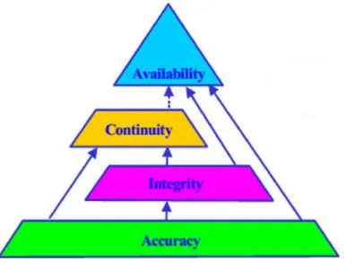
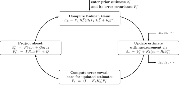
(12) Thèse de Ni Zhu, Université de Lille, 2018. List of Figures 1.1. GNSS Required Navigation Performance (RNP) Parameters for Aviation Navigation . . . . . . . . . . . . . . . . . . . . . . . . . . . . . . . . . . . . . . . .. 4. 1.2. Structure of the Dissertation . . . . . . . . . . . . . . . . . . . . . . . . . . . .. 9. 2.1. GNSS architecture . . . . . . . . . . . . . . . . . . . . . . . . . . . . . . . . .. 14. 2.2. GNSS-based Trilateration . . . . . . . . . . . . . . . . . . . . . . . . . . . . .. 15. 2.3. GNSS Measurement Error Sources . . . . . . . . . . . . . . . . . . . . . . . .. 19. 2.4. Architecture of a Classic GNSS digital receiver . . . . . . . . . . . . . . . . .. 24. 2.5. Kalman Filter Loop [30] . . . . . . . . . . . . . . . . . . . . . . . . . . . . . .. 31. 3.1. An example of impact of positioning for Road User Charge [51] . . . . . . . .. 37. 3.2. Navigation Performance Pyramid: Accuracy, Integrity, Continuity and Availability . . . . . . . . . . . . . . . . . . . . . . . . . . . . . . . . . . . . . . . .. 3.3. © 2018 Tous droits réservés.. 41. Illustration of relationship between integrity parameters and events: PL, AL, PE and MI, HMI. . . . . . . . . . . . . . . . . . . . . . . . . . . . . . . . . . .. 43. 3.4. Stanford Diagram (or Stanford plot) . . . . . . . . . . . . . . . . . . . . . . .. 44. 3.5. Flowchart of classic RAIM algorithms . . . . . . . . . . . . . . . . . . . . . .. 46. 3.6. Global Test . . . . . . . . . . . . . . . . . . . . . . . . . . . . . . . . . . . . .. 56. 3.7. Local Test . . . . . . . . . . . . . . . . . . . . . . . . . . . . . . . . . . . . . .. 57. 3.8. Flowchart of the Classic Test . . . . . . . . . . . . . . . . . . . . . . . . . . .. 60. 3.9. Flowchart of the Subset Test . . . . . . . . . . . . . . . . . . . . . . . . . . .. 60. 3.10 Flowchart of the Iterative Local Test . . . . . . . . . . . . . . . . . . . . . . .. 61. 3.11 Flowchart of the Forward-Backward Test . . . . . . . . . . . . . . . . . . . . .. 63. 3.12 Flowchart of the Danish Method . . . . . . . . . . . . . . . . . . . . . . . . .. 64. 4.1. (left)Multipath interference; (right)NLOS reception [128] . . . . . . . . . . . .. 70. 4.2. Principle of GNSS code delay tracking [129] . . . . . . . . . . . . . . . . . . .. 71. lilliad.univ-lille.fr.
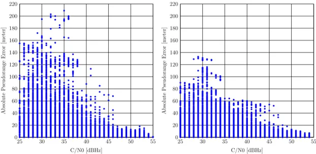
(13) Thèse de Ni Zhu, Université de Lille, 2018. xii. List of Figures. 4.3. Effect of constructive and destructive multipath interference on the correlation function [7] . . . . . . . . . . . . . . . . . . . . . . . . . . . . . . . . . . . . .. 72. 4.4. Histograms of the PR Errors (tails are due to Multipath). . . . . . . . . . . .. 75. 4.5. Absolute Pseudorange Errors as a function of C/N0 in different urban canyons. 77. 4.6. Absolute Pseudorange Errors as a function of Satellite Elevation in different urban canyons . . . . . . . . . . . . . . . . . . . . . . . . . . . . . . . . . . . .. 78. 4.7. Hierarchical representation of DPM models . . . . . . . . . . . . . . . . . . .. 81. 4.8. Urban Trench Model Illustration [35] . . . . . . . . . . . . . . . . . . . . . . .. 85. 4.9. Example of two kinds of streets . . . . . . . . . . . . . . . . . . . . . . . . . .. 86. 4.10 An illustration of the first step of the UMM . . . . . . . . . . . . . . . . . . .. 87. 4.11 An illustration of the second step of the UMM. . . . . . . . . . . . . . . . . .. 87. 5.1. VERT, the vehicle of IFSTTAR used to collect GPS data [155] . . . . . . . .. 92. 5.2. Reference trajectories of the six datasets . . . . . . . . . . . . . . . . . . . . .. 93. 5.3. An overview of the trajectory in the city center of Nantes, France . . . . . . .. 93. 5.4. PR Error Histogram of LOS/NLOS (La Défense) . . . . . . . . . . . . . . . .. 95. 5.5. PR Error Histogram of LOS/NLOS (Nantes) . . . . . . . . . . . . . . . . . .. 96. 5.6. PR Error Histogram of LOS/NLOS (Nantes Center) . . . . . . . . . . . . . .. 96. 5.7. PR Error Histogram of LOS/NLOS (Toulouse) . . . . . . . . . . . . . . . . .. 97. 5.8. Quantile-quantile plot of the PR errors with a normal distribution (Nantes) .. 97. 5.9. 1-σ and 3-σ error envelope of the calibrated model vs the absolute PR errors with respect to the C/N0 (Nantes Center) . . . . . . . . . . . . . . . . . . . .. 99. 5.10 1-σ and 3-σ error envelope of the calibrated model vs the absolute PR errors with respect to the satellite elevation (Nantes Center) . . . . . . . . . . . . . 101 5.11 Absolute PR error, C/N0 and Satellite elevation (LOS signals) . . . . . . . . 103 5.12 Absolute PR error, C/N0 and Satellite elevation (NLOS signals) . . . . . . . . 104 5.13 Hybrid model: LOS and NLOS . . . . . . . . . . . . . . . . . . . . . . . . . . 105 5.14 Cumulative Distribution Function (CDF) of the Horizontal Position Error (HPE) with the total dataset (163503 epochs) . . . . . . . . . . . . . . . . . . . . . . 107. © 2018 Tous droits réservés.. lilliad.univ-lille.fr.
(14) List of Figures. Thèse de Ni Zhu, Université de Lille, 2018. xiii. 5.15 Cumulative Distribution Function (CDF) of HPE (Total Dataset) . . . . . . . 109 5.16 Cumulative Distribution Function (CDF) of the HPE (Nantes Center dataset) 110 5.17 Trajectory and HPE Comparison (Nantes Center) . . . . . . . . . . . . . . . . 111 5.18 An overview Nantes dataset trajectory . . . . . . . . . . . . . . . . . . . . . . 112 5.19 Cumulative Distribution Function (CDF) of the Horizontal Position Error (HPE) with Nantes dataset . . . . . . . . . . . . . . . . . . . . . . . . . . . . . . . . 113 5.20 A skyplot of the initial epoch of Nantes dataset . . . . . . . . . . . . . . . . . 114 5.21 DPM Error Bound Availability for SAT 32, a typical LOS satellite . . . . . . 115 5.22 DPM Error Bound Availability for SAT 31, a typical NLOS satellite . . . . . 116 6.1. An overview of the complete integrity monitoring scheme . . . . . . . . . . . . 123. 6.2. An illustration of Position Error (PE), Alert Limit (AL), Protection Level (PL) in different domains [168] . . . . . . . . . . . . . . . . . . . . . . . . . . . . . 125. 6.3. Composition of the Estimated Position Error Bound . . . . . . . . . . . . . . 131. 6.4. Stanford Diagram for Four Different HPLs Obtained with C/N0 -based WLS estimator without FDE (161724 epochs) . . . . . . . . . . . . . . . . . . . . . 132. 6.5. Stanford Diagram for Four Different HPLs Obtained with Hybrid UMM WLS estimator without FDE (161724 epochs) . . . . . . . . . . . . . . . . . . . . . 133. 6.6. CDF of the Four Different HPLs with Two Weighting Models (161724 epochs) 134. 6.7. HSI of the Four Different HPLs with Two Weighting Models (Total Dataset) . 135. 6.8. Zoomed trajectories . . . . . . . . . . . . . . . . . . . . . . . . . . . . . . . . 137. 6.9. PDOP Increments After Subset Test (Nantes Center) . . . . . . . . . . . . . . 138. 6.10 HPL and HPE by Hybrid UMM without and with FDE techniques . . . . . . 139 6.11 Stanford Diagram by CN0 -based WLS estimator without and with FDE (Total Dataset) . . . . . . . . . . . . . . . . . . . . . . . . . . . . . . . . . . . . . . . 143 6.12 Stanford Diagram by Hybrid UMM WLS estimator without and with FDE (Total Dataset) . . . . . . . . . . . . . . . . . . . . . . . . . . . . . . . . . . . 144. © 2018 Tous droits réservés.. 7.1. A zoom of trajectories . . . . . . . . . . . . . . . . . . . . . . . . . . . . . . . 150. 7.2. A skyplot of the initial epoch of the Nantes Center dataset . . . . . . . . . . . 153. lilliad.univ-lille.fr.
(15) Thèse de Ni Zhu, Université de Lille, 2018. xiv. List of Figures. 7.3. Pseudorange Error and Doppler Error (Nantes Center dataset) . . . . . . . . 154. 7.4. Flowchart of the Innovation-based Classic Test (IBCT) . . . . . . . . . . . . . 157. 7.5. Flowchart of the Innovation-based Danish method. 7.6. A comparison of snapshot WLS residual-based Hslope and the EKF innovation-. . . . . . . . . . . . . . . . 158. based Hslope (Nantes Center Dataset) . . . . . . . . . . . . . . . . . . . . . . 161 7.7. HPE Comparison with the Six Solvers without FDE (Nantes Center Dataset). 165. 7.8. Smoother trajectory by the filtering effects (Nantes Center Dataset) . . . . . 166. 7.9. Receiver Clock Jump (Nantes Center Dataset) . . . . . . . . . . . . . . . . . . 167. 7.10 Horizontal Position Error (HPE) Comparison . . . . . . . . . . . . . . . . . . 168 7.11 Stanford Diagram of WEKF C/N0 + IBCT (Nantes Center Dataset) . . . . . 169 7.12 Stanford Diagram of WEKF Hybrid UMM + IBCT (Nantes Center Dataset). 170. 7.13 Number of Excluded Measurements (Nantes Center Dataset) . . . . . . . . . 171 7.14 Cumulative Distribution Function (CDF) of HPE with C/N0 -based WEKF (Total Dataset) . . . . . . . . . . . . . . . . . . . . . . . . . . . . . . . . . . . 172 7.15 Stanford Diagram of WEKF C/N0 with FDE (Total Dataset) . . . . . . . . . 173 7.16 Cumulative Distribution Function (CDF) of HPE with Hybrid UMM-based WEKF (Total Dataset). . . . . . . . . . . . . . . . . . . . . . . . . . . . . . . 174. 7.17 Stanford Diagram of WEKF Hybrid UMM with FDE (Total Dataset) . . . . 174. © 2018 Tous droits réservés.. lilliad.univ-lille.fr.
(16) Thèse de Ni Zhu, Université de Lille, 2018. List of Tables 2.1. A Summary of GPS Pseudorange Error Budget [7, 22] . . . . . . . . . . . . .. 22. 3.1. Classification of RAIM techniques . . . . . . . . . . . . . . . . . . . . . . . . .. 47. 3.2. Events of a Hypothesis Test . . . . . . . . . . . . . . . . . . . . . . . . . . . .. 54. 4.1. Classification of the GNSS Multipath Mitigation Approaches . . . . . . . . .. 73. 4.2. A Summary of Dataset . . . . . . . . . . . . . . . . . . . . . . . . . . . . . . .. 76. 5.1. C/N0 -based Error Model Coverage Ratio . . . . . . . . . . . . . . . . . . . . . 100. 5.2. Elevation-based Error Model Coverage Ratio . . . . . . . . . . . . . . . . . . 101. 5.3. DPM Parameters . . . . . . . . . . . . . . . . . . . . . . . . . . . . . . . . . . 102. 5.4. Accuracy Performances (Total Data) . . . . . . . . . . . . . . . . . . . . . . . 107. 5.5. Accuracy Performances Summary (Total Dataset) . . . . . . . . . . . . . . . . 108. 5.6. Accuracy Performances Summary (Nantes Center Dataset) . . . . . . . . . . . 109. 5.7. Accuracy Performances Summary (Nantes). 6.1. Statistics of the Four Different HPLs . . . . . . . . . . . . . . . . . . . . . . . 134. 6.2. Performances Summary for C/N0 -based WLS with FDE (Nantes Center) . . . 136. 6.3. Performances Summary for Hybrid UMM WLS with FDE (Nantes Center) . . 138. 6.4. Test Situation Summary (Total Dataset) . . . . . . . . . . . . . . . . . . . . . 140. 6.5. Performances Summary for C/N0 -based WLS with FDE (Total Dataset) . . . 141. 6.6. Refined Analysis on Reliable Positions: C/N0 -based WLS with FDE (Total. . . . . . . . . . . . . . . . . . . . 112. Dataset) . . . . . . . . . . . . . . . . . . . . . . . . . . . . . . . . . . . . . . . 141 6.7. Performances Summary for Hybrid UMM WLS with FDE (Total Dataset) . . 142. 6.8. Refined Analysis on Reliable Positions: Hybrid UMM WLS with FDE (Total Dataset) . . . . . . . . . . . . . . . . . . . . . . . . . . . . . . . . . . . . . . . 142. 7.1. © 2018 Tous droits réservés.. Summary of System DoF and Redundancy . . . . . . . . . . . . . . . . . . . . 150. lilliad.univ-lille.fr.
(17) xvi. Thèse de Ni Zhu, Université de Lille, 2018. List of Tables. 7.2. Spectral Density Parameter Values for Each Dataset . . . . . . . . . . . . . . 152. 7.3. Summary of Accuracy with Six Solvers no FDE Applied (Nantes Center) . . . 165. 7.4. Performances Summary for C/N0 -based WEKF with FDE (Nantes Center) . 166. 7.5. Performances Summary for Hybrid UMM WEKF with FDE (Nantes Center). 7.6. Test Situation Summary (Nantes Center Dataset) . . . . . . . . . . . . . . . . 170. 7.7. Test Situation Summary (Total Data) . . . . . . . . . . . . . . . . . . . . . . 170. 7.8. Performances Summary for C/N0 -based WEKF with FDE (Total Dataset) . . 171. 7.9. Performances Summary for Hybrid UMM WEKF with FDE (Total Dataset) . 173. © 2018 Tous droits réservés.. 167. lilliad.univ-lille.fr.
(18) Thèse de Ni Zhu, Université de Lille, 2018. Acronyms ABAS Airborne-Based Augmentation System. AL Alert Limit. ARAIM Advanced Receiver Autonomous Integrity Monitoring. ATM Air Traffic Management. BDS BeiDou Navigation Satellite System. CDF Cumulative Distribution Function. CS Cycle Slip. CT Classic Test. DLL Delay Lock Loop. DoF Degree of Freedom. DOP Dilution of Precision. DP Dirichlet Process. DPM Dirichlet Process Mixture. ECA Error Characterization Approach. ECEF Earth-Centered Earth-Fixed. EGNOS European Geostationary Navigation Overlay Service. EKF Extended Kalman Filter. ERTMS European Rail Traffic Management System. ESA European Space Agency. ETC Electronic Toll Collection. EU European Union. FB Forward-Backward. FDE Fault Detection and Exclusion.. © 2018 Tous droits réservés.. lilliad.univ-lille.fr.
(19) xviii. Thèse de Ni Zhu, Université de Lille, 2018. Acronyms. GAGAN GPS Aided Geo Augmented Navigation. GBAS Ground-Based Augmentation System. GDOP Geometric Dilution of Precision. GIVE Grid Ionosphere Vertical Error. GLONASS GLObal Navigation Satellite Systems. GNSS Global Navigation Satellite Systems. GPS Global Positioning Systems. GT Global Test. HAL Horizontal Alert Limit. HDOP Horizontal Dilution of Precision. HMI Hazardously Misleading Information. HPE Horizontal Position Error. HPL Horizontal Protection Level. HSI Horizontal Safety Index. HUL Horizontal Uncertainty Level. IBCT Innovation-based Classic Test. IBPL Isotropy-Based Protection Level. ICR Isotropic Confidence Ratio. IGP Ionospheric Grid Points. INS Inertial Navigation System. IR Integrity Risk. IW Inverse-Wishart. JMS Jump Markov System. KF Kalman Filter. LAAS Local Area Augmentation System. LBS Location-Based Service.. © 2018 Tous droits réservés.. lilliad.univ-lille.fr.
(20) Acronyms. Thèse de Ni Zhu, Université de Lille, 2018. xix. LHCP Left-Handed Circular Polarization. LOS Line-of-Sight. LS Least Squares. LT Local Test. MCMF Multi-Constellation Multi-Frequency. MDB Minimum Detectable Bias. MHSS Multiple Hypothesis Separation Solution. MI Misleading Information. MRA Measurement Rejection Approach. MSAS Multi-functional Satellite Augmentation System. MSF Major Satellite Failure. NIS Normalized Innovation Squared. NLOS Non-Line-of-Sight. NSSE Normalized Sum of Squared Error. OLS Ordinary Least Squares. PDF Probability Density Function. PDOP Position Dilution of Precision. PE Position Error. PL Protection Level. PLL Phase Lock Loop. PRN Pseudo Random Noise. PVT Position, Velocity and Timing. RAIM Receiver Autonomous Integrity Monitoring. RANSAC RANdom SAmple Consensus. RHCP Right-Handed Circular Polarization. RNP Required Navigation Performance.. © 2018 Tous droits réservés.. lilliad.univ-lille.fr.
(21) xx. Thèse de Ni Zhu, Université de Lille, 2018. Acronyms. RPM Random Probability Measure. RRP Ratio of Reliable Positions. RTCA Radio Technical Commission for Aeronautics. SBAS Satellite-Based Augmentation System. SISA Signal-In-Space Accuracy. SoL Safety-of-Life. ST Subset Test. TDOP Time Dilution of Precision. TOA Time of Arrival. TTA Time to Alert. UAV Unmanned Aerial Vehicle. UDRE User Differential Range Error. UERE User Equivalent Range Error. UIRE User Ionosphere Range Error. UIVE User Ionosphere Vertical Error. UMF Unobservable Multiple Fault. UMM Urban Multipath Model. URA User Range Accuracy. UTM Urban Trench Model. VAL Vertical Alert Limit. VDOP Vertical Dilution of Precision. VPL Vertical Protection Level. WAAS Wide Area Augmentation System. WEKF Weighted Extended Kalman Filter. WLS Weighted Least Squares.. © 2018 Tous droits réservés.. lilliad.univ-lille.fr.
(22) Thèse de Ni Zhu, Université de Lille, 2018. Chapter 1. Introduction. Contents 1.1. General Context . . . . . . . . . . . . . . . . . . . . . . . . . . . . . . .. 2. 1.2. Research Objectives . . . . . . . . . . . . . . . . . . . . . . . . . . . . .. 5. 1.3. Main Contributions and Publications . . . . . . . . . . . . . . . . . .. 6. 1.4. © 2018 Tous droits réservés.. 1.3.1. Main Contributions . . . . . . . . . . . . . . . . . . . . . . . . . . . . .. 6. 1.3.2. List of Publications. 7. . . . . . . . . . . . . . . . . . . . . . . . . . . . . .. Organization and Structure of the Dissertation . . . . . . . . . . . .. 8. lilliad.univ-lille.fr.
(23) Thèse de Ni Zhu, Université de Lille, 2018. 2. Chapter 1. Introduction. 1.1. General Context. Global Navigation Satellite Systems (GNSS) refers to the total constellations of satellites providing signals from space that transmit positioning and timing data to GNSS receivers. GNSS receivers are able to estimate their own positions with the help of its ranging measurements. Several GNSS constellations exist. Two of them are currently fully functional at a global level: the Global Positioning Systems (GPS) which is maintained by the United States Government, and the GLObal Navigation Satellite Systems (GLONASS) which is operated by the Russian Aerospace Defense Forces. Two additional systems are being planned and completed: the Galileo positioning system by the European Union (EU) and the European Space Agency (ESA), and the Chinese BEIDOU/Compass navigation system. They shall be fully functional by 2020 at the earliest. In the past decades, GNSS have continually evolved and the domains of GNSS-based applications have much extended. These GNSS applications cover a variety of market segments [1]: - Aviation: This segment continues to increasingly rely on GNSS, including the newly emerging Unmanned Aerial Vehicles (UAVs); - Road: More and more GNSS-based road transport applications appear recently, especially the liability critical applications (such as the autonomous vehicles, the Electronic Toll Collection (ETC), etc.). New challenges arise for GNSS since not only accuracy but also integrity are required by these applications; - Rail: Railways have already introduced satellite-based localization systems for nonsafety related applications. Driven by economic reasons, the use of these systems for new services and, in particular, their introduction in signaling system is seriously investigated today and tested all around the world (such as the European Rail Traffic Management System (ERTMS)). [2] - Location-Based Service (LBS): This segment covers lots of GNSS applications in daily life, such as the typical software applications for smartphones which require knowledge about where the user is located. According the user’s positions, the LBS could provide the user with the nearest sites of interest (restaurants, banks, post offices etc.); - Others: GNSS-based applications are not limited to the segments above. A wide range of GNSS-based applications exist such as maritime navigation, agriculture management, timing and synchronization for different sectors, etc. Among all the GNSS-based applications mentioned above, there is a high coverage of urban applications. The demand for cost-effective but highly capable GNSS navigation devices for urban utility is clearly growing at an exponential rate. GNSS-based urban applications. © 2018 Tous droits réservés.. lilliad.univ-lille.fr.
(24) Chapter 1. Introduction. Thèse de Ni Zhu, Université de Lille, 2018. 3. present challenging tasks for GNSS navigation since GNSS signals are distorted by multipath and attenuated by fading effects due to numerous obstacles in urban environments. For certain newly emerged urban GNSS-based applications, such as ETC or the ERTMS mentioned above, not only the positioning accuracy but also its reliability is required. And the latter has recently attracted more and more attention from urban GNSS users. If we reclassify all the GNSS-based applications based on the level of reliability, they can be divided into the following three categories: - Safety-critical: This refers to the applications, in which the occurrence of a positioning error can lead to death or physical injuries. We can also call them Safety-of-Life (SoL) services. A typical example of this category is the GNSS-based Air Traffic Management (ATM); - Liability-critical: For liability-critical applications, the computed Position, Velocity and/or Time (PVT) are used as the basis for legal decisions or economic transactions. Large positioning errors can lead to wrong legal decisions or wrong charge computations such as for ETC. - No liability: This category include all the other GNSS-based applications which don’t fit the two categories mentioned above. For instance, the LBS applications are no liability. In fact, the reliability defined here corresponds to one of the Required Navigation Performance (RNP) parameters for aviation navigation (Fig.1.1): integrity. Integrity is defined as a measure of trust which can be placed in the correctness of the information supplied by the total system [3]. Traditionally, integrity monitoring has focused on the safety-critical applications such as approach or landing phases of airplanes. The integrity monitoring algorithms for aviation utility are well designed (such as the Receiver Autonomous Integrity Monitoring (RAIM)) and the corresponding specifications are set in detail in [4]. And this research is still being progressing towards the use of Multi-Constellation Multi-Frequency (MCMF) GNSS, such as the Advanced Receiver Autonomous Integrity Monitoring (ARAIM). Meanwhile, several GNSS augmentation systems (such as the American Wide Area Augmentation System (WAAS) and the European Geostationary Navigation Overlay Service (EGNOS)) transmit integrity information, which can help guarantee the positioning integrity for civil aviation users. Nevertheless, the existing aviation integrity monitoring algorithms, their specifications as well as the integrity information provided by augmentation systems are not appropriate to be used directly for applications in urban environments. This is because urban environment is quite different from the open-sky. Urban environments present great challenges to common commercial GNSS receivers. The. © 2018 Tous droits réservés.. lilliad.univ-lille.fr.
(25) 4. Thèse de Ni Zhu, Université de Lille, 2018. Chapter 1. Introduction. Figure 1.1 – GNSS Required Navigation Performance (RNP) Parameters for Aviation Navigation main difficulty for GNSS positioning in urban environments is the existence of local effects due to the nearby obstacles. The most harmful ones are known as Non-Line-of-Sight (NLOS) reception and the multipath interference. These two phenomena are not exactly the same although sometimes they occur together. The multipath phenomenon refers to the case that the reflected signals are received together with the Line-of-Sight (LOS) signal while the NLOS reception occurs when the LOS signal is blocked and only the reflected signal is received. The latter one is particularly common in dense urban areas where tall buildings block lots of signals. The multipath phenomenon and the NLOS receptions strongly affect the positioning quality that can introduce large errors (up to several kilometers). Moreover, the satellite visibility is usually poor in urban canyon because of obstacles. However, the algorithms developed in aviation fields are under the assumption that only one failure occurs at a time and based on the fact that a high data redundancy exists. These are hardly true in urban environments due to the reasons mentioned above. No doubt, it is essential to guarantee the positioning performances, such as accuracy and integrity, for urban transport applications, especially the liability critical ones. How to improve positioning accuracy by eliminating the frequent measurement faults and how to correctly transfer the concept of integrity from civil aviation applications to the mass-market urban GNSS applications are currently hot topics since no well-developed integrity monitoring algorithm is ready to be implemented by the urban applications in real time.. © 2018 Tous droits réservés.. lilliad.univ-lille.fr.
(26) Chapter 1. Introduction. 1.2. Thèse de Ni Zhu, Université de Lille, 2018. 5. Research Objectives. As described in the previous paragraphs, GNSS positioning performances, especially accuracy and integrity, are usually poor in urban environments due to existing local effects. For personal navigation applications, especially liability-critical ones, knowing one’s positions as well as the certainty of the positioning information provided by navigation system are extremely important. The global objective of this research work is to improve the geolocation service quality of GNSS in constrained environments. The geolocation performances targeted here in this research work are mainly GNSS positioning accuracy and integrity with the presence of severe signal disturbances such as multipath and NLOS. Thus, more precisely, this overall objective can be divided into the following sub-objectives: 1. The first phase of this thesis is mainly to better characterize the GNSS measurement errors in stringent environments in order to improve GNSS positioning accuracy. So it is necessary to analyze the main sources of GNSS measurement errors especially the local effects induced by multipath and the NLOS receptions. This includes: - To review and to implement the existing measurement error models, which allow considering the real-time local effects. To evaluate and to compare their performance with real GNSS data collected in urban environments. - To propose new error models which can better characterize measurement errors in urban environments for low-cost commercial GNSS receivers. 2. The second main part of this research work is to guarantee the GNSS positioning integrity for urban personal navigation applications as well as the liability critical ones. That is to say, the erroneous measurements should be detected and further identified if possible. Ideally, if the detection, identification and exclusion of faulty measurements can be properly done, the GNSS positioning integrity can be well guaranteed and its accuracy can also be improved. But the challenges lie on the fact that, firstly, in urban environments, there is often not enough redundancy to realize the identification or even detection. Secondly, when the multiple simultaneous faults happen, the erroneous measurements can possibly correlate among them or even be "absorbed" by their geometry in such a way as to produce a large position error but very small residuals [5], which will make these faults unobservable by the integrity monitoring algorithms. All these challenges make this topic a hot issue in the current GNSS research society. Due to the complexity of the GNSS integrity monitoring in urban environments described above, the following sub-objectives will be studied in this thesis: - To review the state of the art of the existing integrity monitoring techniques for. © 2018 Tous droits réservés.. lilliad.univ-lille.fr.
(27) Thèse de Ni Zhu, Université de Lille, 2018. 6. Chapter 1. Introduction aviation and road transport utilities. To understand the difficulties and limitations of implementing the existing integrity monitoring algorithms for urban transport applications;. - To analyze and to evaluate the existing Fault Detection and Exclusion (FDE) algorithms allowing eliminating multiple faults in order to summarize their advantages and disadvantages. 3. Based on the first two phases of research work above, a complete integrity monitoring scheme for low cost urban navigation equipments will be proposed. More precisely, if the first part of this research work concerning the characterization of the measurement errors can be effectively done, it can already reduce or correct measurement errors from upstream of the system. Then, this can already contribute to improving the capability of FDE. Finally, a statistical position error bound, Horizontal Protection Level (HPL), can be calculated. Though the total processing adds complexity to the computation of navigation solution, this integrity monitoring system can enhance navigation accuracy or at least when the fault identification is not available, the system can provide warning to users in the case of unreliable positioning. Other sensor hybridizations can be involved afterwards in order to achieve a possibly sub-meter or lane-level accuracy but this is not included in the objective of this thesis.. 1.3. Main Contributions and Publications. 1.3.1. Main Contributions. The main contributions of this thesis are as follows: - Providing a complete review of the state of the art for the GNSS positioning integrity monitoring in urban environments while analyzing the limitations of the existing integrity algorithms established in aviation domain as well as the possible research directions around this issue; - Presenting and analyzing the existing GNSS measurement error models which allow taking into account the real-time local effects. These models are tested and evaluated with real GPS data collected in urban canyons using Weighted Least Squares (WLS) estimator; - Proposing a novel GNSS measurement error model which combines the information of C/N0 (carrier-power-to-noise-density ratio), satellite elevations, the signal reception state LOS/NLOS as well as the range corrections for NLOS signals. The signal reception. © 2018 Tous droits réservés.. lilliad.univ-lille.fr.
(28) Chapter 1. Introduction. Thèse de Ni Zhu, Université de Lille, 2018. 7. states and the range corrections are provided by error models established with the help of digital maps, i.e., the Urban Trench Model (UTM) and the Urban Multipath Model (UMM); - Optimizing the Urban Trench Model (UTM) model by developing a simplified ray tracing model called Urban Multipath Model (UMM) while getting rid of the infinite length street assumption; - Analyzing and evaluating several HPL computation methods for the snapshot residualbased Receiver Autonomous Integrity Monitoring (RAIM) existing in the literature while choosing the one adapted best for urban GNSS-based applications. - Evaluating the performance of several FDE techniques with real GPS data, including Classic Test (CT), Subset Test (ST), iterative Local Test (LT), Forward-Backward (FB) Test as well as the Danish Method; - Proposing the concept of Weighted Extended Kalman Filter (WEKF) by scaling the measurement covariance matrix with the help of more realistic error models; - Analyzing the differences located between the WLS residual-based snapshot FDE and the Extended Kalman Filter (EKF) innovation-based FDE. Their performances are evaluated with real GPS data collected in urban environments. - Proposing a complete GNSS integrity monitoring scheme for low cost urban transport navigation system by combining the accuracy enhancement module and the FDE techniques with two classes of estimators (WLS or EKF). The HPL are also calculated and evaluated. - Proposing a HPL computation method in the framework of EKF innovation-based integrity monitoring algorithm by taking into consideration the potential impact of the former fault on the current navigation solution. The proposed scheme can enhance GNSS navigation accuracy as well as integrity in stringent environments. This thesis evaluated both snapshot and sequential filtering integrity monitoring approaches. Further extensions, such as hybridizations with different sensors, are possible but not included in the framework of this thesis.. 1.3.2. List of Publications. In the framework of this PhD research work, the following publications are published in some international conferences or journals: * [P1]: Ni Zhu, Juliette Marais, David Bétaille, Marion Berbineau (2017). Evaluation and Comparison of GNSS Navigation Algorithms Including FDE for Urban Transport. © 2018 Tous droits réservés.. lilliad.univ-lille.fr.
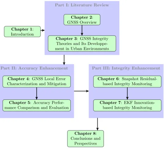
(29) Thèse de Ni Zhu, Université de Lille, 2018. 8. Chapter 1. Introduction Applications, Proceedings of the Institute of Navigation (ION) International Technical Meeting (ITM), January 30-February 2, 2017, Monterey, California, United States. * [P2]: Ni Zhu, Juliette Marais, David Bétaille, Marion Berbineau (2017). Evaluation and Comparison of GNSS Navigation Integrity Monitoring Algorithms for Urban Transport Applications, Young Research Seminar (YRS), May 16-18, 2017, Berlin, Germany. * [P3]: Ni Zhu, Juliette Marais, David Bétaille, Marion Berbineau (2018). GNSS Position Integrity in Urban Environments: A Review of Literature. IEEE Transactions on Intelligent Transportation Systems (ITS), Vol.19, Issue 9, pp2762-2778, 17p. DOI: 10.1109/TITS.2017.2766768. * [P4]: Ni Zhu, David Bétaille, Juliette Marais, Marion Berbineau (2018). GNSS Integrity. Enhancement for Urban Transport Applications by Error Characterization and Fault Detection and Exclusion (FDE), Les Journées Scientifiques 2018 d’URSI (Union RadioScientifique Internationale)-France, Géolocalisation et Navigation, March 28-29, 2018, Meudon, France. * [P5]: Ni Zhu, David Bétaille, Juliette Marais, Marion Berbineau (2018). Extended Kalman Filter (EKF) Innovation-based Integrity Monitoring Scheme with C/N0 Weighting, 2018 IEEE 4th International Forum on Research and Technology for Society and Industry (RTSI) (RTSI 2018), September 10-13, 2018, Palermo, Italy. * [P6]: Ni Zhu, David Bétaille, Juliette Marais, Marion Berbineau (2018). GNSS Integrity Enhancement for Urban Transport Applications by Error Characterization and Fault Detection and Exclusion (FDE), REE: Revue de l’électricité et de l’électronique after the conference of the URSI (International Union of Radio Science) 2018. * [P7]: Ni Zhu, David Bétaille, Juliette Marais, Marion Berbineau, GNSS Integrity Monitoring Schemes for Terrestrial Applications in Harsh Environments, submitted to IEEE Intelligent Transportation Systems Magazine (Special Issue on GNSS for ITS) the 1st September.. 1.4. Organization and Structure of the Dissertation. With the two main objectives defined above, i.e., to improve the GNSS positioning accuracy and to guarantee its integrity in urban environments, the main content of this dissertation is divided into three parts, in which, 8 chapters are included. Fig. 1.2 depicts the structure of this thesis, which is organized as follows: * Part I. The first part contains the literature review, inside which there are two chapters:. © 2018 Tous droits réservés.. lilliad.univ-lille.fr.
(30) Thèse de Ni Zhu, Université de Lille, 2018. Chapter 1. Introduction. 9. Part I: Literature Review Chapter 2: GNSS Overview Chapter 1: Introduction Chapter 3: GNSS Integrity Theories and Its Developpement in Urban Environments. Part II: Accuracy Enhancement. Part III: Integrity Enhancement. Chapter 4: GNSS Local Error Characterization and Mitigation. Chapter 6: Snapshot Residualbased Integrity Monitoring. Chapter 5: Accuracy Performance Comparison and Evaluation. Chapter 7: EKF Innovationbased Integrity Monitoring. Chapter 8: Conclusions and Perspectives. Figure 1.2 – Structure of the Dissertation – Chapter 2 provides an overview of GNSS system. This includes the introduction of GNSS measurement models, error sources as well as different GNSS position estimators; – Chapter 3 presents the current state of the art of the GNSS position integrity monitoring in urban environments. * Part II. The second part includes two chapters which mainly address the local effects in urban environments and the error characterizations: – Chapter 4 deals with the characterization of the errors due to local effects in constraint environments. Several error models existing in the literature are discussed. Moreover, a hybrid model, taking into consideration the the information of C/N0 (carrier-power-to-noise-density ratio), satellite elevations, the signal reception state LOS/NLOS as well as the range corrections provided by the geometry feature of the digital map, is proposed. – Chapter 5 firstly makes the calibration for the error models described in Chapter. © 2018 Tous droits réservés.. lilliad.univ-lille.fr.
(31) Thèse de Ni Zhu, Université de Lille, 2018. 10. Chapter 1. Introduction 4. Then these error models are evaluated and tested with real GPS data collected in urban canyons by Weighted Least Squares (WLS) estimators. The accuracy performance is compared.. * Part III. The third part includes also two chapters concerning the integrity monitoring with two classes of approaches: – Chapter 6 proposes a complete snapshot residual-based integrity monitoring scheme. Five FDE techniques and several HPL computation methods are discussed. Finally, the complete scheme is evaluated with real GPS data collected in urban canyons. – Chapter 7 aims at designing an Extended Kalman Filter (EKF) innovation-based integrity monitoring approach, which is a parallel class with the snapshot approach in Chapter 6. Firstly, the concept of Weighted Extended Kalman Filter (WEKF) is proposed by implementing several error models evaluated in Chapter 5 into the EKF. Then, the derivation of HPL computation in the framework of innovationbased approach is made and a new method of HPL computation is proposed. The complete scheme is evaluated with real data collected in urban canyons. * Chapter 8 draws the conclusions and addresses the possible perspectives for future work.. © 2018 Tous droits réservés.. lilliad.univ-lille.fr.
(32) Thèse de Ni Zhu, Université de Lille, 2018. Part I. LITERATURE REVIEW. © 2018 Tous droits réservés.. lilliad.univ-lille.fr.
(33) Thèse de Ni Zhu, Université de Lille, 2018. © 2018 Tous droits réservés.. lilliad.univ-lille.fr.
(34) Thèse de Ni Zhu, Université de Lille, 2018. Chapter 2. Global Navigation Satellite Systems (GNSS). Contents 2.1. Introduction of the Global Navigation Satellite Systems (GNSS). .. 14. 2.1.1. An Overview of GNSS . . . . . . . . . . . . . . . . . . . . . . . . . . . .. 14. 2.1.2. GNSS augmentation systems . . . . . . . . . . . . . . . . . . . . . . . .. 16. 2.2. Measurement Models . . . . . . . . . . . . . . . . . . . . . . . . . . . .. 17. 2.3. Error Sources . . . . . . . . . . . . . . . . . . . . . . . . . . . . . . . . .. 19. 2.4. 2.3.1. Nominal Error Sources . . . . . . . . . . . . . . . . . . . . . . . . . . . .. 19. 2.3.2. Error Sources in Fault Cases . . . . . . . . . . . . . . . . . . . . . . . .. 23. GNSS Position Estimators . . . . . . . . . . . . . . . . . . . . . . . . .. 24. 2.4.1. Least Square Estimator and Weighted Least Square Estimator . . . . .. 25. 2.4.2. Kalman Filter (KF) Position Estimator . . . . . . . . . . . . . . . . . .. 28. 2.4.3. Performance Improvement with Other Aiding Approaches . . . . . . . .. 32. Summary This chapter aims at introducing the fundamental theories and backgrouds of the Global Navigation Satellite Systems (GNSS). The review of GNSS principles in this section can facilitate the comprehension of the integrity monitoring theories in following chapters. The discussion of this chapter is mainly based on [6–8] and other references mentioned in the text. The structure of this chapter is as follows: it begins with an overview of GNSS positioning principles. This followed by an introduction of GNSS measurement models and their mathematical expressions. Then the measurement error sources will be detailed according to signal propagation channel. Finally, different GNSS position estimators will be briefly introduced.. © 2018 Tous droits réservés.. lilliad.univ-lille.fr.
(35) Thèse de Ni Zhu, Université de Lille, 2018. 14. Chapter 2. Global Navigation Satellite Systems (GNSS). 2.1. Introduction of the Global Navigation Satellite Systems (GNSS). 2.1.1. An Overview of GNSS. Global Navigation Satellite Systems (GNSS) is a generic term denoting the constellations of satellites providing signals from space that transmit positioning and timing data which enable users to determine their three-dimensional position with global coverage. Several GNSS constellations exist. The US Global Positioning System (GPS) is fully operational since 1995. The Russian GLObal NAvigation Satellite System (GLONASS) was restored to full operation in December 2011. The Chinese BeiDou Navigation Satellite System (BDS) and the European GALILEO system are currently under development although the BDS started an initial operating service (Phase II) in late December 2011 and Galileo has been declared operational in december 2016 for initial services. Generally speaking, a GNSS constellation can be divided into three major segments as shown in Fig.2.1:. Figure 2.1 – GNSS architecture - Space segment: This segment comprises the satellites from which users make ranging measurements. The main functions of the space segment are to generate and transmit code and carrier phase signals, and to store and broadcast the navigation messages uploaded by the control segment. The space segment of a GNSS constellation with global coverage must ensure at least four satellite in view simultaneously from any point on the Earth’s surface at any time. - Control segment: This segment is also referred to as the ground segment, which is responsible for the proper operation and functioning of the system. It is usually composed of a network of ground infrastructures, such as control stations, ground antennas, etc. They can help to control and maintain the satellite constellation status, to predict. © 2018 Tous droits réservés.. lilliad.univ-lille.fr.
(36) Chapter 2. Global Navigation Satellite Systems (GNSS). Thèse de Ni Zhu, Université de Lille, 2018. 15. ephemeris and satellite clock evolution as well as to update the navigation messages for all the satellites. - User segment: This segment refers to all kinds of user receiving equipments, typically referred to as "GNSS receivers". GNSS receivers are capable of receiving GNSS signals transmitted by satellites, determining the pseudo-distances (or other measurements), then providing Position, Velocity and Timing (PVT) solutions.. Figure 2.2 – GNSS-based Trilateration GNSS receivers utilize the concept of one-way Time of Arrival (TOA) ranging and trilateration mechanism to determine its position on the surface of the Earth. That is to say, the receiver will measure the time it takes for a signal transmitted by a satellite at a known location to reach the receiver itself. The signal propagation is multiplied by the speed of light to obtain the emitter-to-receiver distance, which is called pseudo-distance or pseudo-range. As a result of this measurement process, the user would be located on the surface of the sphere centered on the satellite with the corresponding measured pseudo-range as radius (shown in Fig.2.2). If several pseudo-range measurements can be simultaneously made by different satellites, the user will be located on the intersection of several spheres centered at each satellite. In order to determine user positions in three dimensions (xu , yu , zu ) as well as the receiver clock offset with respect to system time δtu , at least four pseudo-range measurements are needed.. © 2018 Tous droits réservés.. lilliad.univ-lille.fr.
(37) Thèse de Ni Zhu, Université de Lille, 2018. 16. Chapter 2. Global Navigation Satellite Systems (GNSS). 2.1.2. GNSS augmentation systems. For aviation utilities, the performances of the standalone GNSS cannot meet the signal-inspace requirements for certain flight modes, such as the accuracy for precision approaches and integrity monitoring for any operation. For this reason, different augmentation systems are developed in order to enhance the GNSS performance and allow its use in civil aviation to meet the ICAO specifications. The main augmentation systems can be classed into three categories according to the source of information from which the user receive the augmentation information: - Ground-Based Augmentation System (GBAS): The augmentation information of GBAS is provided by groud-based transmitters. Based on a network of ground station references, GBAS can provide estimates of common-mode errors and detect GNSS faults and anomalies. And integrity information can be obtained by comparing the true position of the ground reference and the estimated position obtained from the GNSS. This kind of augmentation system is mainly used at a local level, typically in airports. An example of the GBAS is the Local Area Augmentation System (LAAS), which is based on real-time differential correction of the GPS signal. - Satellite-Based Augmentation System (SBAS): The augmentation information of SBAS is provided by satellite-based transmitters. SBAS transmits differential corrections and integrity messages for navigation satellites that are within sight of a network of stations, typically deployed for an entire continent. All the SBAS satellites signals covering a given zone are monitored in order to update the error model at the raw range measurement level. Several famous example of SBAS: the US Wide Area Augmentation System (WAAS), the European European Geostationary Navigation Overlay Service (EGNOS), the Japanese Multi-functional Satellite Augmentation System (MSAS) and the Indian GPS Aided Geo Augmented Navigation (GAGAN). - Airborne-Based Augmentation System (ABAS): The augmentation information of ABAS is autonomously calculated within the aircraft equipment. It can provide integrity monitoring for the position solution using redundant information within the GNSS constellation. ABAS is usually referred to as Receiver Autonomous Integrity Monitoring (RAIM) when GNSS information (range measurements) is exclusively used and as Aircraft Autonomous Integrity Monitoring (AAIM) when information from additional on-board sensors (e.g. barometric altimeter, clock and Inertial Navigation System, INS) are also used.. © 2018 Tous droits réservés.. lilliad.univ-lille.fr.
(38) Chapter 2. Global Navigation Satellite Systems (GNSS). 2.2. Thèse de Ni Zhu, Université de Lille, 2018. 17. Measurement Models. The GNSS pseudorange measurement model is a key input for the design of integrity monitoring algorithms and the prediction of the statistical positioning error bounds since it summarizes measurement error budgets. In general, GNSS receivers provide two main types of pseudorange measurements from satellites: code and carrier phase measurements. A code peudorange measurement P is obtained as the time difference between the emission time and reception time of the signal. This time is then scaled by the speed of light c to obtain the pseudodistance. A carrier phase pseudorange measurement φ is obtained by estimating the phase shift of the local carrier. This phase can be expressed as a distance by converting radians into meters using the carrier wavelength. The code pseudorange measurement P and the carrier phase pseudorange measurement φ at the epoch k for the satellite i can be mathematically described with the following equations in units of length: i P i (k) = ρi (k) + c(δtu (k) − δti (k)) + diI (k) + diT (k) + Dmult (k) + nip (k). φi (k) = ρi (k) + c(δtu (k) − δti (k)) − diI (k) + diT (k) + φimult (k) + niφ (k) + N i λi. (2.1) (2.2). where, - ρi represents the true geometric distances between the receiver and the satellite i; - δtu represents the advance of the receiver clock with respect to system time; - δti represents the advance of the satellite clock with respect to system time; - diI represents the ionospheric propagation delay residual; - diT represents the tropospheric propagation delay residual; i and φimult represent the error due to multipath on the code and phase pseudo-ranges; - Dmult. - nip and niφ represent measurement noises on code and phase pseudo-ranges; - N i represents the carrier phase ambiguity; - λi represents the wavelength of the carrier. We can see from the expressions above that the differences between the code and phase pseudorange measurements are located mainly on the residual error due to ionospheric propagation and the presence of an unknown integer number of carrier phase cycles N i , which is called ambiguity: - The ionospheric effects on carrier phase pseudorange measurements is an advance while on code pseudorange measurements is a delay. This is due to the differences of the refractive index. The phase refractive index is less than the unity resulting in a phase velocity that is greater than the speed of light in vacuum (i.e., phase advance) while the group refractive index is greater than the unity resulting in a group velocity that is less than the speed of light in vacuum (i.e., group delay). [9]. © 2018 Tous droits réservés.. lilliad.univ-lille.fr.
(39) Thèse de Ni Zhu, Université de Lille, 2018. 18. Chapter 2. Global Navigation Satellite Systems (GNSS). - The carrier phase pseudorange measurements are ambiguous. The solution of the integer ambiguity N , the number of whole cycles on the path from satellite to receiver, is the key to fast and high precision GNSS positioning. But the ambiguity resolution is more difficult in urban environments since the existence of local effects can lead to frequent tracking loss and Cycle Slip (CS). Besides, the two kinds of pseudo-range measurements possess different characteristics: - The code pseudorange measurements are robust and not ambiguous. But they are more affected by tracking errors due to noise and multipath. They are the basic measurements generally used to estimate the position. - The carrier phase pseudorange measurements are less affected by tracking errors due to noise and multipath. But they are not robust due to frequent measurement losses (loss of carrier tracking) and Cycle Slip (CS). Moreover, the presence of ambiguity prevents carrier phase measurements from acting as absolute measurements to estimate the PVT. The process to fix these ambiguities is very sophisticated especially in adverse reception conditions such as urban canyons. As a result, we will only concentrate on the code pseudorange measurements during this research work. In order to determine the user position in three dimensions (x, y, z) and the receiver clock offset δtu , the code pseudorange measurements can be rewritten into following form by developing the true geometry distance as a function of user and satellite positions: q P i (k) = (x(k) − xi (k))2 + (y(k) − y i (k))2 + (z(k) − z i (k))2 + cδtu (k) + ei (k). (2.3). where: - x, y, z are the Cartesian coordinates of the receiver antenna at the time of signal reception expressed in an Earth-centered Earth-fixed (ECEF) reference frame; - xi , y i , z i are the Cartesian coordinates of the ith satellite antenna at the time of signal emission expressed in an ECEF reference frame; - ei (k) represents the sum of the code measurement errors mentioned in Eq. (2.1), i.e., i ei (k) = diI (k) + diT (k) + Dmult (k) + nip (k) − cδti (k).. The non-linear relationship in Eq. 2.3 can be expressed in the following vector form: Y (k) = h(X(k)) + E(k). (2.4). where, - Y (k) represents the pseudorange measurement vector at epoch k with size [m × 1]; - X represents the navigation solution vector at epoch k with size [n × 1];. © 2018 Tous droits réservés.. lilliad.univ-lille.fr.
(40) Chapter 2. Global Navigation Satellite Systems (GNSS). Thèse de Ni Zhu, Université de Lille, 2018. 19. - E(k) represent pseudorange measurement error vector at epoch k with size [m × n]; Pseudorange measurement errors are the addition of nominal errors and faults: E =ε+B. (2.5). where, - ε represents the nominal error vector with size [m × 1];. - B represents the fault vector with size [m × 1].. 2.3. Error Sources. Figure 2.3 – GNSS Measurement Error Sources. 2.3.1. Nominal Error Sources. The nominal error model characterizes the pseudorange measurement errors that are present when all GNSS segments are working according to their specifications and the magnitudes of other external error sources have typical values. GNSS measurements are affected by several error sources mainly including satellite clock and orbit error tropospheric residual error, ionospheric residual error, multipath error as well as the receiver noise error as shown in Fig. 2.3. All these nominal errors are modeled as zero-mean independent normal distributions in civil. © 2018 Tous droits réservés.. lilliad.univ-lille.fr.
Figure
![Figure 3.1 – An example of impact of positioning for Road User Charge [51]](https://thumb-eu.123doks.com/thumbv2/123doknet/3622430.106440/58.892.218.687.786.1033/figure-example-impact-positioning-road-user-charge.webp)
+7


![Figure 4.3 – Effect of constructive and destructive multipath interference on the correlation function [7]](https://thumb-eu.123doks.com/thumbv2/123doknet/3622430.106440/93.892.238.630.107.372/figure-effect-constructive-destructive-multipath-interference-correlation-function.webp)

Documents relatifs