This is an author-deposited version published in:
http://oatao.univ-toulouse.fr/
Eprints ID: 5432
To link to this article: DOI:
10.1007/s11235-013-9702-5
URL:
http://dx.doi.org/10.1007/s11235-013-9702-5
To cite this version:
Zhang, Lei and Sénac, Patrick and Lochin, Emmanuel
and Diaz, Michel A cross-layer architecture to improve mobile host rate
performance and to solve unfairness problem in WLANs. (2013)
Telecommunication Systems. ISSN 1018-4864
O
pen
A
rchive
T
oulouse
A
rchive
O
uverte (
OATAO
)
OATAO is an open access repository that collects the work of Toulouse researchers and
makes it freely available over the web where possible.
Any correspondence concerning this service should be sent to the repository
administrator:
[email protected]
A Cross-Layer Architecture to Improve Mobile Host Rate Performance
and to Solve Unfairness Problem in WLANs
Lei Zhang
1, Patrick S´enac
2, Emmanuel Lochin
2, Michel Diaz
21
INRIA Lille - Nord Europe, Univ Lille Nord de France, USTL, CNRS UMR 8022, LIFL, France
2
CNRS ; LAAS ; 7 avenue du colonel Roche, F-31077 Toulouse, France
Universit´e de Toulouse ; UPS, INSA, INP, ISAE ; LAAS ; F-31077 Toulouse, France
{patrick.senac, emmanuel.lochin}@isae.fr, [email protected]
Abstract
The evolution of the Internet has been mainly promoted in recent years by the emergence and proliferation of wireless access networks towards a global ambient and pervasive network accessed from mobile devices. These new access networks have introduced new MAC layers in-dependently of the legacy “wire-oriented” protocols that are still at the heart of the protocol stacks of the end systems. This principle of isolation and independence between layers advocated by the OSI model has its draw-backs of maladjustment between new access methods and higher-level protocols built on the assumption of a wired Internet. In this paper, we introduce and deliver solu-tions for several pathological communication behaviors resulting from the maladjustment between WLAN MAC and higher layer standard protocols such as TCP/IP and UDP/IP. Specially, based on an efficient analytical model for WLANs bandwidth estimation, we address in this paper the two following issues: 1) Performance degrada-tion due to the lack of flow control between the MAC and upper layer resulting in potential MAC buffer over-flow; 2) Unfair bandwidth share issues between various type of flows. We show how these syndromes can be efficiently solved from neutral “cross layer” interactions which entail no changes in the considered protocols and standards.
1
Introduction
The rapid spreading of Wireless Local Area Networks (WLAN) access networks makes it possible to offer perva-sive broadband communications capabilities. Specially, the next generation of the IEEE 802.11n standard for
Wireless Local Area Networks is being standardized by integrating several powerful techniques like Multiple-Input Multiple-Output (MIMO) [1] and 40MHz opera-tion [2] to the physical layer which deliver higher trans-mission rates and offer wider signal coverage. Such evolu-tion is part of the emerging heterogeneous 4G infrastruc-ture made up of different promising technologies. Nowa-days, most researches about WLAN focus either on the wireless communication technology itself to improve the transmission efficiency (i.e. transmission rate, interfer-ence avoidance, etc), or on upper-layers protocols and mechanisms for efficient mobility management. However, few works have addressed some intrinsic problems result-ing from integration of the IEEE 802.11 access method with legacy higher layers protocol stacks.
This paper proposes a solution for a more efficient in-tegration of the WLAN MAC layer with legacy upper layer protocols such as UDP, TCP or TCP Friendly Rate Control (TFRC) [4]. This integration is based on light cross interactions between the MAC layer and the net-work layer or transport layer. These interactions lever-age on a light and accurate analytical model of the dy-namic bandwidth offered by the WLAN MAC layer. This model uses a small set of parameters that can be easily monitored and can be efficiently processed by light mo-bile devices. The output of this analytical model is then used by several rate adaptation mechanisms applied at the network, transport or applications layers. The three contributions of this paper are:
1. the developpement of an analytical model based on [31] that takes into consideration the characteristics of transport layer such as TCP, UDP and TFRC (developed Section 4);
layer rate modelling) at the network and transport layer (as a function of the transport protocol used), allowing to prevent MAC buffer overflow (developed Section 5);
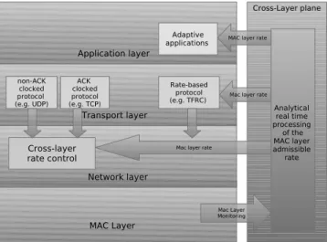
3. the demonstration that both implementations, com-bined with a cross layer mechanism that monitors MAC layer rate and computes the optimal bitrate at the network; transport or application layer (based on Section 4 and enhanced Section 6), allows to solve unfairness problems for different types of flows such like TCP, UDP and TFRC (evaluated Section 7). To illustrate how the analytical model developed in this paper interacts with other layers, we represent in Figure 1 the interactions insured by the cross-layer plane between different layers. By monitoring the MAC layer, our ana-lytical model allows to assess the MAC layer admissible rate that becomes a key metric allowing the other layers (network, transport and application layers) to take bene-fit of the supplementary information provided. As shown in this paper, the promoted approach makes it possible to correct efficiently various critical performance anoma-lies and syndromes that plague current wireless networks; delivering a generic solution for a great diversity of flows (UDP, TCP, TFRC, both upload or download). This paper extends our previous contribution [3] by consider-ing the case of ACK-clocked flows such as TCP and by proposing a concrete implementation (Section 5) at the network and transport layers of our scheme.
Figure 1: Cross-layer architecture
This paper is organized as follows: Section 2 gives some related work. Section 3 experimentally reveals the nature
and scale of the maladjustment between MAC and upper layers legacy protocols. Section 4 introduces a generic an-alytical model to accurately estimate the available band-width delivered by the WLAN MAC layer. Leveraging on this model, Sections 5 and 6 present light and simple cross layer solutions to respectively solve rate maladjust-ment and unfairness issues. Section 7 focuses on the validation of this contribution through various represen-tative simulation scenarios. Finally, Section 8 concludes this paper.
2
Related Work
This related work investigates 1) existing cross layer ap-proach which aim at proposing an accurate, efficient and light bandwidth estimation scheme to deliver to upper layers a real time value of the bandwidth offered to each node by the wireless LAN and 2) unfairness issue. As both issues are strongly linked together (i.e MAC buffer overflow and unfairness), we propose a list of contribu-tions that sometimes attempt to solve both problems.
Unfairness issue remains a crucial problem in the IEEE 802.11 context. In particular, a set of TCP fairness prob-lems in WLAN is given in [24]. In [16], the authors have proposed a formal model of interference to estimate the maximum rate at which flows can safely send traffic with-out overloading the network. This work has been ex-tended in [17], where authors developed a model which enables an accurate prediction of the resulting through-put of individual flows, and also allows one to improve flows’ fairness for both UDP and TCP flows. Several other studies [11, 12, 13, 14, 21] have also addressed this issue. In [19], the authors have proposed a Cross-Layer Based High Throughput MAC protocol, based on a prob-ing technique, to completely utilize the channel band-width and increase the fairness of each flow without caus-ing congestion. In [34], authors present station-centric Markov chain models of WLAN cross-layer performance aimed at capturing complex interactions between ARF, DCF, and TCP to tractable and accurate performance predictions. Compare to our proposal, none of them takes into account the whole complexity of the communi-cation context associated to a WLAN access point, such as the mobile node’s dynamical transmission status, flows profiles and the different protocols which can be possibly involved (i.e. UDP, TCP, TFRC, ACK-clocked, Non-ACK-clocked flows).
Some other work focus on the near-optimum mecha-nisms to optimize the throughput of the active nodes to the MAC layer’s available rate. In [18], the authors pro-pose a mechanism which involves a PHY-MAC dialogue
and splits collisions’ resolution and the transmission data scheduling into two distributed logical queues, to achieve the maximum capacity of channel. Compare to our so-lution, such approach requires significant changes to the standard IEEE 802.11.
Koksal et al. describe in [9] a scenario where TCP per-formance might dramatically degrades because of short term unfairness exhibited by MAC protocols. In [8], au-thors lead an in depth analysis on the TCP fairness over Wireless LAN, they conclude that the buffer size at the base station plays an important role in the observed un-fairness. Even in a scenario that considers only TCP connections, the unfairness in throughput ratio between upstream and downstream flows can be significant. This unfairness symptom has been addressed in [10] and an Asymmetric Access Point based method has been pro-posed. A new estimation based backoff algorithm which supports variable packet length was proposed in [30] to improve the unfairness problem, but this mechanism is at the price of a decrease of the throughput. In [29], per-flow queueing was proposed to alleviate the TCP unfair-ness, however, it employs a very complex mechanism to manage per-flow queues for all the uplink and downlink TCP flows. This problem has also been studied in [26] by proposing an IEEE 802.11e MAC EDCF based mecha-nism. In [32], authors propose a cross layer based scheme, which makes the PHY layer information transparent to MAC layer, to provide efficient resource allocation and solve the unfairness problems, and in [33], authors pro-pose a cross layer feedback approach in which the MAC layer at the AP measures the per-station channel uti-lization and system wide channel utiuti-lization to calculate the channel access cost, then the TCP sender adjusts its sending rate based on the access cost, so as to assure per-station fairness and to maximize channel utilization. In [22], authors argue that TCP connections can use the available capacity in a very unfair way under the context of WLAN networks. A rate limiter technique is proposed to avoid critical starvation and unfairness in different sce-narios. Unfortunately, only TCP connections are taken into consideration in their context of study. In [27], the authors propose that the contention windows of mobile stations can be dynamically adjusted, the access point (AP) has more chance to access the wireless channel by increasing the contention windows, and improves the fair-ness issues among uplink and downlink flows. Similarly, in [28], the AP can possesses higher priority in access-ing the channel by adjustaccess-ing DIFS in AP. In [35] and [35], other cross-layer approaches based on loss differen-tiation are proposed to improve TCP performance over WLAN. In [20], authors argue that the notion of per-node fairness employed by the IEEE 802.11 standard is
not suitable for a multi-hop wireless network where flows can traverse multiple hops, and the authors proposed a new MAC protocol that supports prioritized per-node fairness and significantly improves performance in terms of both throughput and fairness. In [25], authors also give a careful study on the TCP unfairness issues be-tween Uplink and Downlink Flows, and proposes a dual queue based scheme in an access point (AP) to solve the unfainess problem. In [23], authors propose a new MAC scheme that dynamically optimizes each active node’s backoff process, and allows optimize the throughput and fairness. However, those solution either require signifi-cant modifications to the current IEEE 802.11 standard or does not take into account the whole complexity of the communication context. The authors in [15] proposed a rate control mechanism which achieves a fair and effi-cient rate allocation by offering explicit congestion no-tification, however it still relies on an additive increase, multiplicative decrease technique to probe network ca-pacity which induces slow convergence rate.
3
Experimental Diagnostic
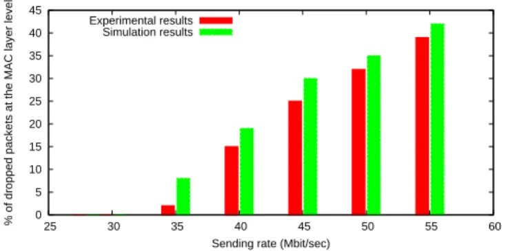
Packet losses in wireless networks are usually attributed to the wireless channel characteristics. However, as ex-perimentally shown in this section, rate maladjustment between the WLAN MAC layer and upper layer legacy protocols can also significantly contribute to packet losses. Indeed, the WLAN medium access method can entail important discrepancies between the upper lay-ers sending rate and the rate offered by the MAC layer. We have already experimentally demonstrated that the lack of rate control between upper layers and the WLAN MAC layer can dramatically contribute to the packet loss experimented by UDP and TFRC flows [3]. Using an ex-perimental testbed similar to the one presented in Fig-ure 3. A mobile node sends a UDP flow (packets size 1500bytes) to a remote wired node (receiver) via an ac-cess point (AP) which is 1m distant from the mobile host. Both wireless stations run FreeBSD6.1 and use ifinfo tool in order to check the number of packets sent by the wireless interface. This tool returns information from the wireless card and in particular: the instantaneous length, the maximum length and the number of drops in the send queue of the wireless interface. The sender MAC buffer is set to 50 packets. We measure the percentage of losses according to the sender node rate. We made a similar simulation scenario with OPNET. The results of these simulations and experiments, as illustrated in Fig-ure 2, show that the throughput at the transport layer can reach or surpass the maximum bandwidth that the
MAC layer can support and can lead to massive MAC buffer overflow and significant packet loss rate.
0 5 10 15 20 25 30 35 40 45 25 30 35 40 45 50 55 60
% of dropped packets at the MAC layer level
Sending rate (Mbit/sec) Experimental results
Simulation results
Figure 2: Percentage of packets lost on the MAC buffer as a function of the sending rate.
We now propose to illustrate the impact of these losses on the behavior of a TCP flow in real conditions.
We are not interested in quantifying the exact number of TCP losses as it depends on the wireless card used. In-deed, the MAC buffer characteristics might be differently sized following the card or the system in use. Thus, we propose to generate a TCP traffic from a mobile host to a wired host through a wireless access point as illustrated in Figure 3.
This traffic consists in a file transfer of 15min dura-tion. The wireless station is connected to the Base Sta-tion (BSS) with an IEEE 802.11b access mode and the transmission rate is set to 1Mbps. Behind the BSS, a wired host is connected at 100Mbps. In order to iden-tify possible TCP losses which occur at the MAC layer of the wireless node, we realize a tcpdump capture [6] at the IP level at the wireless input of the BSS (denoted wlan0 in Figure 3). The traffic is generated from the GNU/Linux wireless node to the wired host. We use a TCP New Reno version with a TCP window size set to the maximum size (64000 bytes). In order to identify MAC layer losses associated to a TCP flow, we look the
Access Point
Wireless Node Fixe Node
100Mb/s
wlan0 eth0
TCPDUMP capture Measurement point
Figure 3: Testbed to illustrate MAC buffer overflow.
time sequence
number
Loss between BSS and fixed node (in our case: loss in the MAC buffer)
Loss between MN and BSS
Figure 4: Detecting packet loss from the sequence num-ber pattern.
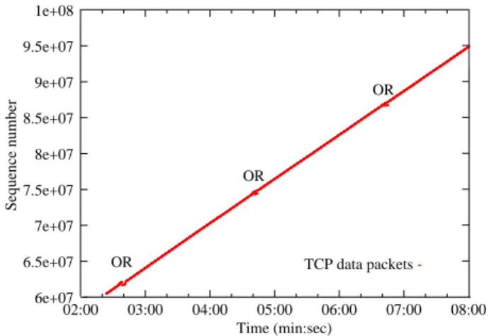
BSS trace for out of order packets following the well-known algorithm described in [7]. The principle of this algorithm is as follows: if the BSS observes a hole in the TCP sequence number followed by an out of order packet, then this means that a loss occurred between the Mobile Node (MN) and the BSS. However, if a duplicate sequence number is observed, this means that a loss oc-curred between the BSS and the wired node. Indeed, a duplicate sequence number corresponds to a retransmis-sion of a packet lost after its capture by the BSS, while a rupture in the sequence means a loss before the BSS capture as illustrated in Figure 4. We have analyzed the TCP traces and observed periodic bunches of lost packets (every 2 minutes in our experiment), as shown in Figure 5 (“OR” represents the out-of-order data). Figure 6 is a zoom of an “OR”. We have also verified that no losses occurred on the wireless and wired paths. As a matter of fact, since no losses occurred on the wired path and since we observe duplicate data packets at this measurement point, we can conclude that these losses occur inside the MAC layer buffer.
The periodic character of these losses clearly suggests that they are due to buffer overflow instead of channel losses (which should be very rare and occur randomly according to the “perfect” communication experimental conditions). In this experiment, we found that 555 over 79159 packets were dropped due to MAC buffer over-flow (several others experiments have shown that this value oscillates between 0.7% and 0.5% with the same experimental conditions). We observed that an average of 90 packets (±10) are lost during every loss period. As a matter of fact, this bunch of losses is obviously prej-udicial for TCP flows performance. Such losses can be much more significant if the size of MAC buffer decreases or in scenarios where other nodes (specially greedy UDP mobile nodes) are involved. Therefore the lack of rate
6e+07 6.5e+07 7e+07 7.5e+07 8e+07 8.5e+07 9e+07 9.5e+07 1e+08 02:00 03:00 04:00 05:00 06:00 07:00 08:00 OR OR OR TCP data packets Sequence number Time (min:sec)
Figure 5: MAC overflow of TCP flow
control between the WLAN MAC layer and the upper layers impacts negatively on the quality of service (i.e. reliability, delay) delivered to all the types of flows that can be transmitted by wireless nodes (i.e. UDP, TCP, TFRC).
In order to prevent this issue, we propose to make the upper layer aware of the rate offered by the WLAN MAC layer. Moreover, in complement with this awareness we have to introduce in the upper layers a cross layer rate control mechanism that prevents MAC layer losses to happen. The following section describes an analytical model that makes it possible for wireless nodes to process the available rate offered by their WLAN with a slight processing overhead and a low complexity.
4
Modelling MAC Layer rate as a
function of the upper transport
protocol
This section introduces an analytical model which accu-rately estimates the available bandwidth delivered by the WLAN MAC layer according to a few parameters that can be easily monitored by an access point and period-ically broadcast to mobile nodes. The proposed model pushes further the model proposed in [31] and consider the general case where ACK-clocked (i.e. TCP) and Non-ACK clocked (i.e. UDP) flows are mixed. Firstly, before describing our model, we introduce in the following sub-sections several related issues and concepts.
7.4e+07 7.41e+07 7.42e+07 7.43e+07 7.44e+07 7.45e+07 7.46e+07 7.47e+07 7.48e+07 7.49e+07 7.5e+07 04:35 04:36 04:37 04:38 04:39 04:40 04:41 04:42 04:43 04:44 04:45 04:46 Sequence number Time (min:sec) TCP data packets
Figure 6: Zoom of Figure 5 between Time 04:00 and 05:00 focused on the ”OR”
4.1
Issues related to ACK-clocked flows
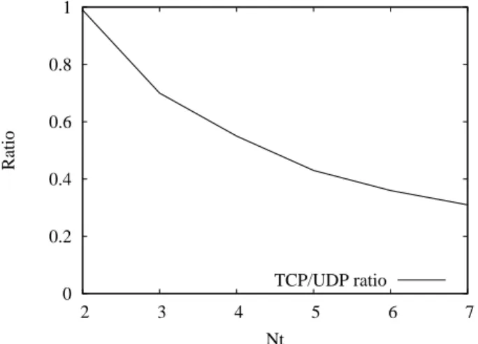
Flow unfairness can be observed when ACK-clocked (TCP) and Non-ACK-clocked (UDP) flows coexist1. Let us suppose there are several TCP and UDP based up-loading mobile nodes in the IEEE 802.11 access point (AP) coverage. In the context of IEEE 802.11, AP is con-sidered as a normal contention based mobile node, it has the same opportunity of sending packets (specially ACK packets to all the TCP based sending mobile nodes) as any competing mobile node. Therefore, the bandwidth available to forward ACK packets by the AP is, roughly speaking, conversely proportional to the number of nodes sending UDP flows. We denote K: the number of ac-knowledged TCP segments by each ACK2 in the steady state (i.e. in congestion avoidance phase). When the number of TCP flow sending nodes (Nt) is higher than K, the reduced pace of returned ACK packets towards the flow sources decreases proportionally their sending rate. Therefore in this case, the nodes sending TCP flows cannot make full use of the available bandwidth offered by the WLAN MAC layer. The bandwidth un-used by the TCP flow sending nodes is thus captured by the Non-ACK-clocked flows (UDP connections) which are not limited by the return pace of ACK packets. This
1
In this section, we point out that we always refer to data ac-knowledgement packets (ACK) from the transport layer.
2
We choose to set K = 2 as most of TCP stacks today en-able delayed acknowledgments by default. Indeed, both Windows XP and Linux use this value with a maximum delay of 200ms for Windows and 100ms for Linux. These values are tunable from the key registry entry TcpAckFrequency in Windows and through
behavior is analyzed in section 4.3 where it is shown that the rate share between TCP and UDP node tends to K
Nt
if Nt> K and tends to 1 if Nt6K (packet sizes of the TCP and UDP are supposed equals). This conclusion has also been validated by simulations with OPNET [5]. For instance, when we consider two UDP flow sending nodes and NtTCP flow sending nodes (all the nodes are with a transmission rate of 11Mbps), Figure 7 shows the simulated rate ratio between each TCP and UDP node as a function of Nt (we set K = 2). This unfairness be-tween the ACK-clocked and Non-ACK clocked flows is identified as the “ACK effect” in this paper.
0 0.2 0.4 0.6 0.8 1 2 3 4 5 6 7 Ratio Nt TCP/UDP ratio
Figure 7: Rate ratio between each TCP and UDP node
4.2
Overall transmission duration of the
IEEE 802.11 MAC layer data frame
The average overall duration to transmit one MAC layer data frame includes:
1. the duration to transmit one data frame, which strongly depends on the transmission rate Ri, Ri ∈ (1, 2, 5.5, 11M bps) in the context of IEEE 802.11b;
2. the overhead duration that includes DIFS, SIFS, two times the PLCP preamble and the header sion time, as well as the MAC-layer ACK transmis-sion time;
3. the average duration of the back-off process, which depends on the number of competing mobile nodes attached to the same AP. The calculation of such overall duration is presented in [3].
4.3
Maximum bandwidth delivered by
the IEEE 802.11 MAC layer to TCP
and UDP flows
An accurate model of the rate offered to each WLAN node must take into account the fact that some nodes do not use fully the offered bandwidth. We define as greedy node, a node whose sending rate is equal or higher than the maximum bandwidth that the MAC layer can sup-port. On the contrary, we define as rate sparing node, the one with a throughput lower than the available band-width offered by the MAC layer (i.e. a VoIP node that requires a relatively low bandwidth) or congestion con-trol constraints. These “rate sparing nodes” do not make a full use of the bandwidth offered by the MAC layer. Therefore, rate sparing nodes can alleviate the contention level of the WLAN MAC layer and give more sending op-portunities to greedy nodes.
Due to the “ACK effect”, when the number of TCP uploading mobile nodes surpasses K (K = 2 is the most current use case), we observe a bandwidth share unfair-ness issue between UDP and TCP flows. In this case, MAC buffer overflow is not observed for the TCP flow sending nodes during our simulations and experiments. This behavior is due to the self clocking property of TCP flows and the resulting implicit flow control operated at the TCP transport layer. Therefore, this section will mainly focus on the estimation of the IEEE 802.11 MAC-layer available rate for UDP based nodes while taking into consideration the coexistence of TCP and UDP flows sent by the mobile nodes.
For the sake of simplicity and without loss of general-ity, we consider Nt TCP sending nodes and Nu UDP “greedy” sending nodes in the coverage of an IEEE 802.11b AP. Ni
t and Nui (i= 1; 2; 3; 4) represent respec-tively the number of TCP and UDP mobile nodes using a transmission rate Ri, Ri∈(1, 2, 5.5, 11M bps). Firstly, we suppose that each TCP based sending node has the same number of TCP flows. We denote Ti
ta: the overall duration for transmitting an ACK packet from AP to a TCP based uploading mobile node which belongs to the group Ni
t. We also denote P c(N ), the proportion of col-lisions experienced for each packet successfully acknowl-edged at the MAC level, whose analytical expression is given in [3]. When Nt> K, the average interval (T ) be-tween the two successive emissions of UDP packets from the same UDP node comprises the following four parts:
1. T1: the time required for sending packets by the TCP based sending nodes that are limited by the “ACK effect”: P4i=1(Ni
t.Tti.
K
Nt), where T
i t repre-sents the duration for sending a TCP packet from
the mobile nodes in group Ni
t. This formula can be explained as follows: since AP can be considered as a normal node, it has the same opportunity of ing ACK packets as any of the UDP based send-ing node. In the stationary state in which the AP and the UDP nodes are continuously ready to send packets, we consider that between two UDP packet transmitted by the same mobile nodes, one ACK packet can be forwarded to a TCP node by the AP, and then a right to emit K TCP packets is offered to this TCP node. This right to emit K packets is statistically shared by the NtTCP uploading nodes individually able to transmit the equivalent of K
Nt
packets;
2. T2: the time required by each UDP node to send one packet: P4i=1(Ni
u.T
i u) , T
i
u represents the duration of sending a UDP packet from the node in group Nui;
3. T3: the time required to send one ACK packet by AP to one TCP uploading node,
P4
i=1(T i ta.Nti)
Nt . This
ACK packet can be sent to any node amongst the NtTCP uploading nodes;
4. T4: the time spent in collisions (Tcol), Tcol = P c(Nu+ K + 1).tjam.(Nu+ K + 1). When Nt> K, NtTCP nodes are equivalent to K competing nodes that make full use of the bandwidth delivered by the MAC layer. Furthermore, since the AP is con-sidered as a normal competing mobile node, there-fore we have a resulting “equivalent” total number of (Nu+ K + 1) greedy competing mobile nodes. Then we have: T = 4 X i=1 (Ni t. K Nt .Tti) + 4 X i=1 (Ni u.T i u) + 4 X i=1 (Ti ta. Nti Nt ) + Tcol (1) where tjam represents the average time spent in colli-sion for TCP-UDP coexisting flows, whose calculation is given in appendix.
When Nt6K, TCP mobile nodes are no longer lim-ited by the “ACK effect” and are able to make full use of the bandwidth delivered by the IEEE 802.11 MAC layer. Thus, we have T 1 =P4i=1(Ni
t.Tti) T3 = Nt K. P4 i=1(T i ta.Nti) Nt = P4 i=1(T i ta.Nti) K and Tcol= P c(Nu+ Nt+NKt).tjam.(Nu+ Nt+NKt). Ti
t, Tuiand Ttai can be calculated according to the anal-ysis in Section 4.2.
With the resulting expression of T , which gives the average interval between two successive emission UDP packets from the same UDP node, we can calculate the maximum sending throughput, Xm, offered by the MAC layer to each UDP sending node:
Xm=
S
T (2)
With S: the length of MAC layer packet in bits. The maximum available throughput at the transport layer is: Xt= St T = Xm. St S (3)
With St:the length of transport layer packet in bits. Note, the modeling result also represents the maxi-mum bandwidth supported by the IEEE 802.11 MAC
layer for TCP based nodes when Nt 6 K. When
Nt> K, the available throughput at the transport layer for TCP node equals to Xt.NK
t in average.
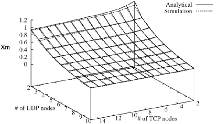
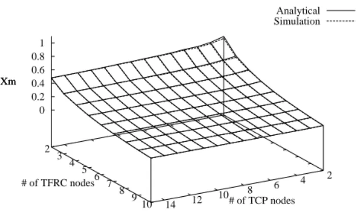
This analytical model has been validated by a set of simulations with OPNET. Figure 8,9,10 show that the analytical model and the simulations deliver strongly similar results. These Figures plot the analytical and simulation values of Xmaccording to the number of TCP nodes (N = [2,15]) and the number of the UDP nodes (N = [2,10]) for three different scenarios in which two mobile nodes (one UDP and one TCP node) have a transmission rate of 11Mbps and all the other mobile nodes have re-spectively a transmission rate of 5.5Mbps, 2Mbps, 1Mbps (corresponding respectively to scenario 1,2 and 3).
2 4 6 8 10 12 14 2 3 4 5 6 7 8 9 10 0 0.2 0.4 0.6 0.8 1 1.2 Xm Analytical Simulation # of TCP nodes # of UDP nodes Xm
2 4 6 8 10 12 14 2 3 4 5 6 7 8 9 10 0 0.2 0.4 0.6 0.8 1 Xm Analytical Simulation # of TCP nodes # of TFRC nodes Xm
Figure 9: TCP/UDP scenario 2
Despite the presence of novel protocols such as DCCP or SCTP, TCP and UDP remain the two dominant trans-port protocols currently used. The analytical model in-troduced in this section takes into account both the im-pact of the “ACK effect” and imim-pact of the instantaneous mobile nodes’ transmission rate. This is a generic model as it can be used to process the MAC layer available rate for a large family of ACK-clocked or Non-ACK-clocked flows. The way of integrating mobile nodes’ profiles in the bandwidth estimation analytical model has been dis-cussed and validated in [3].
We have also applied this model to estimate the avail-able rate delivered by the IEEE 802.11 MAC layer to a mix of UDP and TFRC based mobile nodes.
The following part of this paper will focus on how the analytical model can be used to solve two intrinsic prob-lems of the IEEE 802.11 MAC layer that lead to serious performance degradations and symptomatic behaviors:
1. performance degradation due to the lack of flow con-trol between the MAC and upper layer resulting in potential massive MAC buffer overflow;
2. unfair bandwidth share issues.
5
Implementing Flow control
be-tween the MAC and Upper
Layers
In the previous section, we have introduced an analyti-cal model to process the maximum available sending rate
2 4 6 8 10 12 14 2 3 4 5 6 7 8 9 10 0 0.2 0.4 0.6 0.8 1 Xm Analytical Simulation # of TCP nodes # of TFRC nodes Xm
Figure 10: TCP/UDP scenario 3
delivered by the IEEE 802.11 MAC layer to each mobile node. We have shown in Section 3 that when the sending rate from upper layer exceeds this rate, MAC layer buffer can be overflowed leading to potential massive packet losses due to the lack of rate control between the MAC layer and higher layers. Such a pathological behavior is mainly due to the independence promoted by the OSI model between its different layers. This feature is at the origin of potential maladjustment between the different layers such as the lack of flow control between the upper layers and the MAC layer. Specially, for transport flows such as TCP (when Nt6K) UDP or TFRC, the classi-cal WLAN MAC buffer size is not big enough to induce a buffer based closed-feedback loop that would implicitly adjust the TCP or equation based TFRC sending rates from the varying Round Trip Time (RTT) entailed from the buffering delay. Therefore, the adaptation of upper layer sending rate (i.e. TCP and TFRC sending rate) to the available rate supported by MAC layer is mainly done from packet losses in the MAC buffer, which entails a potentially dramatic sub-optimal reduction of the TCP and TFRC sending rates. In this section, we propose a cross layer based approach resulting from a cooperation between the MAC and the upper layer that aims to avoid MAC layer overflow and results in the improvement of the QoS (that is loss rate, bandwidth, delay and jitter) delivered to TCP, UDP and TFRC flows. More precisely, we have experimented two levels of cross layer interac-tions that implement respectively flow control either at the network layer on flow aggregates or at the transport layer on a per flow basis.
5.1
IP Shaper
We propose the use of a generic rate based flow con-trol mechanism, such as an IP layer traffic shaper, which will be applied to a multiplex of UDP, TCP and TFRC flows. It is worth noting that such approach is applied to the aggregate of transport flows and entails no change to the various transport layers. This network layer shaper is integrated at the IP layer (with a defined size B) of each mobile node to adapt the aggregated sending rates from transport layer to the delivered rate supported by the MAC layer (Xt). Today, there exists several IP shaper algorithms implemented at the IP layer that can be used to enable our scheme without heavy develop-ment (such as Dummynet in FreeBSD systems or Netem in GNU/Linux).
As underlined by the simulation and real experimental results, this approach reduces packet losses at the MAC layer and smooths transport layer rate variations, and as a consequence improves the QoS delivered to appli-cations’ flows. From a practical point of view, the pro-cessing of the MAC layer available rate can be operated by the Access Router (AR) or Access Point (AP). This offered rate can be calculated from dynamic parameters that can be easily monitored in real time (e.g. PLCP frame fields of received packets, MAC address, etc.) and broadcast to the mobile nodes by the AR/AP. Because the buffer size at the IP layer is larger than the MAC layer one, the resulting buffer-based closed-feedback loop allows implicitly adjusting the sending rate of self clocked flows (TCP or TFRC flows for instance) according to RTT variation resulting from IP buffering. This self ad-justment leads to significant losses reduction at the MAC layer.
For TFRC flows, several feedback packets are config-ured to be sent back to the TFRC sender during one RTT in order to better and faster adapt the TFRC sending rate. However, our hypothesis is that the network bot-tleneck is not situated inside the core network but in the access network. Our approach induces an efficient avoid-ance of losses at the MAC layer, therefore the TFRC loss event rate is kept low so resulting in smoother rate vari-ations and more reliable transport service. A set of sim-ulation done for TFRC flows have proved that IP buffer overflow, because of the RTT increase entailed by the additional IP layer buffering, is much less frequent than MAC layer overflow when the MAC buffer is involved alone. This improvement is mainly due to the IP buffer based closed-feedback loop which implicitly adjusts the TFRC sending rate.
IP layer shaping can be also applied to TCP flows when Nt 6K. In this case, when the aggregate throughput
of the TCP transport layer is higher than the rate Xt, the RTT increases because of the buffering at IP layer, which implicitly impacts on the TCP sending rate. In other words, this closed feedback loop allows the aggre-gate TCP sending rate varying around the shaped limited throughput Xtaccording to the varying RTT.
Compared to the constant MAC buffer size, the size of IP buffer can be parametrized and dynamically adjusted. We consider that our proposal introduces a “novel equiv-alent MAC buffer” that is configurable to replace static and constant MAC buffer size which is implemented in-side the wireless card and not modifiable. However, the trade-off must be found between large buffer sizes, which allows progressive rate self-adaptation with low rate loss but potential high delays and small buffers that can entail frequent losses at the benefit of low end to end delays.
When considering UDP flows, their sending rate can also be constrained by the IP shaper to the MAC layer available rate. When the sending rate from these “not rate and congestion controlled transport flows” exceeds Xt, an exception is raised by the IP layer and propagated by an up call to the application layer that is aware of its rate maladjustment and can adapt its behavior. There is a clear advantage of the IP shaper solution over the default blind behavior of the UDP based applications. For instance when considering a UDP based video trans-mission, the application can apply codec change or video resolution reduction (a VLC transcode functions for in-stance) to lower its sending rate, then avoiding MAC losses and resulting in continuous video transmission.
5.2
Transport rate limiter
In this section we will show how the proposed flow con-trol mechanism can be implemented as a rate limiter ap-plied on individual flow at the transport layer. However such approach is quite limited because it can only be implemented within rate-based protocols (e.g. TFRC) on a flow per node basis and therefore, is less univer-sal than the IP shaper solution. We have also imple-mented such scheme for the sake of completeness. In the context of TFRC flows, the processed TFRC equation based sending rate Xtf rc can be bounded by the maxi-mum transport layer bandwidth Xtoffered by the MAC layer, resulting in a transport sending rate Xsend given by the following equation which is a simple additional constraint introduced in the final step of the processing of the TFRC rate:
Xsend= min(Xtf rc, Xt) (4)
However, such a transport layer rate adaptation should be applied on a flow per node basis. It can raise the
issue of fair bandwidth share if several different trans-port flows are produced by the end systems and can lead to a complex management of the global rate shared by the various transport layer flows. Indeed, when several flows co-exist on the same system, their respective trans-port layer rate must be dynamically adapted according to their dynamic profiles. Therefore, such a transport layer approach increases greatly the complexity of the proposed flow control mechanism compared to the cross layer solution between the network and the MAC layer (IP shaper).
6
Rate equalization mechanisms
to fairness issues
Among the various performance syndromes intrinsic to the CSMA/CA access method, unfairness is one of the most challenging issue. We introduce in this section an approach that tackles two main unfairness problems re-lated to IEEE 802.11:
1. unfairness between UpLink (UL) and DownLink (DL) flows, which has been discussed in [3];
2. unfairness between ACK-clocked and Non-ACK-clocked flows, which will be detailed in the current section.
6.1
Unfairness
improvement
between
UL and DL
In the context of IEEE 802.11, the access point (AP) has to compete with other sending nodes to send pack-ets to the downloading mobile nodes. In other words, an AP is considered as a normal mobile node and has the same probability of sending packets (to all the DL mo-bile nodes) as any of the uploading momo-bile node. This feature leads to an unfairness issue between the UL and DL flows. This unfairness symptom is more significant for the Non-ACK-clocked flows (i.e. UDP, TFRC flows) than for TCP flows. Indeed, the bandwidth captured by each UL mobile node equals to the aggregated DL bandwidth obtained by all the DL mobile nodes. In [3], we give a cross layer based solution which constrains the upper-layer sending rate of each UL mobile node to a rate, Xf air, which ensures a fair bandwidth share be-tween UL and DL flows. This approach allows the AP to gain an additional bandwidth for DL transmission, which allows each DL node to obtain an identical fair bandwidth Xf air. Simulation results in [3] have demon-strated that such an end to end approach is able to
en-sure a fair share of the bandwidth between upload and download flows.
6.2
Unfairness
improvement
between
ACK-clocked and Non-ACK-clocked
flows
We have mentioned in Section 4.1 that the “ACK ef-fect” can induce dramatic unfair bandwidth share be-tween ACK-clocked (i.e. TCP) flows and the other ones. Indeed, when the number of TCP uploading nodes (Nt) surpasses the number of segment Acked by each ACK, the contention avoidance procedure implemented at the IEEE 802.11 MAC layer can slower the TCP sending rate because the AP cannot gain enough sending op-portunity of sending ACK packets back to the upload-ing mobile nodes. However, this effect has no influence to the Non-ACK-clocked based uploading mobile nodes that can still make full use of the bandwidth delivered by the IEEE 802.11 MAC layer. Similarly to the anal-ysis presented above, the principal of our proposal is to constrain the sending rates of Non-ACK-clocked flows to allow the AP to gain more sending opportunity for for-warding ACK packets, therefore to increase the sending rate of the ACK-clocked flows.
Let us consider for instance a set of Nu UDP (Non-ACK-clocked) and NtTCP (ACK-clocked) flows for in-stance. If Nt6K, no specific action has to be applied since UDP and TCP flows share fairly the upload band-width. Therefore, we focus on the case where Nt> K. In this case we suppose that the average bandwidth of each greedy uploading UDP node is R packets/sec (which cor-responds to Xm processed by our analytical model) and the packet sizes S are supposed to be identical for TCP and UDP flows to simplify the analysis, Sack denotes the size of TCP ACK packet in bits. The aggregated band-width obtained by all the TCP uploading mobile nodes is equivalent to the bandwidth captured by K UDP nodes. So the aggregated bandwidth (X) exchanged between the AP and all the mobile nodes is given by:
X= Nu.R.S+ R.Sack+ R.K.S (5)
where
R= Xm
S (6)
If we suppose that every TCP and UDP node get the same fair rate Xf air bps (corresponding to Rf air pack-ets/sec), then we have,
X= (Nt+ Nu).Rf air.S+
Nt.Rf air
Wireless Nodes
10 Mbit/s
Fixed nodes
Access Point Hub
Figure 11: Simulation testbed
Xf air= Rf air.S (8)
where, Nt.Rf air
K represents the number of TCP ACK
packets that must be sent by the AP for continuously feeding the TCP flows. Therefore the fair bandwidth share which should ideally allocated to each node is given by:
Xf air =
(Nu+ K).Xm+Xm.SSack Nt+ Nu+NtK.S.Sack
(9) Following our promoted cross layer approach, we con-strain the sending rate of each UDP node to Xf airin or-der to deliver a fair bandwidth share to the TCP nodes. Therefore, this mechanism allows the AP to gain more sending opportunities to forward ACK packets, which corresponds to an additional bandwidth of (Nt.Rf air
K −R)
packets/sec. Thus, each TCP node is no longer con-strained by the “ACK effect” and gets the same network bandwidth as each UDP node.
7
Simulation and validation
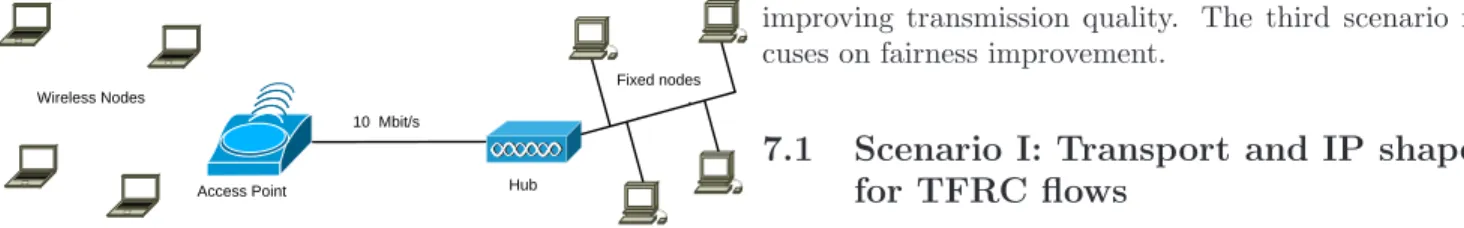
We present in this section several scenarios to show that the approaches introduced in the previous sections can prevent losses at MAC layer and deliver a fair bandwidth share between the nodes and flows. In the following simulation scenarios, we set the link bandwidth capac-ity of the access router to C = 10Mb/s in order to have C >>PN1 Xm with N: the number of mobile nodes. As a result, Xm is the bottleneck rate between the mobile node and its correspondent node (see Figure 11 which presents the testbed used). The size of data frame (St) is 8192bit (MPDU size S = 8624bit including IEEE 802.11 MAC header with 4 bytes for WEP: 34 bytes; and IPv4 header: 20 bytes), the maximum TCP ACKed segments: K = 2. In all the following simulations, the traffic gen-eration starts at t = 15sec. In the first two scenarios, we show the impact of the transport and IP shaper solutions for avoiding MAC layer overflows and for substantially
improving transmission quality. The third scenario fo-cuses on fairness improvement.
7.1
Scenario I: Transport and IP shaper
for TFRC flows
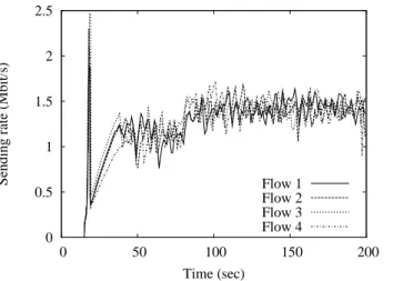
In this scenario, we suppose that 4 TFRC mobile nodes are transmitting data to a remote server via the same AP, two of the mobile nodes keep using a transmission rate of 11Mb/s. The other two mobile nodes use the transmis-sion rate of 5.5Mb/s between t = [15sec, 80sec]. When the captured signal gets better since they are moving towards the access point, their transmission rates turn up to 11Mb/s at t = 80sec. During the first phrase t = [15sec, 80sec], Xt as processed by the AP equals to 1.14Mb/s. From t = 80sec, Xtrises to 1.48Mb/s. Since the bottleneck is always situated at the MAC layer of each mobile node, the transport shaper allows the send-ing rate Xsend (inserted in the TFRC protocol) to be bounded to Xtto avoid congestion and losses at the MAC layer.
Then we reproduce the same simulation scenario for the IP shaper approach, we suppose that there are three greedy TFRC connections for one of the moving mobile nodes (denoted M NIP). In order to alleviate the IEEE 802.11 MAC layer congestion, we bound to Xt the IP layer sending rate. Figure 12 shows the sending rate of default TFRC flows, Figure 13 and Figure 14 show the sending rates of transport shaper based TFRC flows and the IP shaper based flow which aggregates the three TFRC sending rates of the mobile node M NIP. After the slow-start phase, 1.51 packets per second on aver-age are dropped by the MAC layer for the default TFRC flows while zero packets are dropped for Transport and IP Shaper based flows. Although an oscillation of the transport sending rate can be observed when IP shaper approach is applied (as Figure 14 illustrates), the sending rate at the MAC layer is constant at a value of Xm. The simulation results illustrate that our proposal efficiently avoids losses specially at the MAC layer and substan-tially improves the quality of the transmission (in term of reliability, delay, jitter and burstiness).
7.2
Scenario II: Transport shaper for
UDP/TCP coexisting flows
In this scenario, we suppose that there are three TCP uploading mobile nodes (M Nt1, M Nt2, M Nt3) and three UDP uploading mobile nodes (M Nu1, M Nu2, M Nu3) in the coverage of the same AP. M Nt3 and M Nu3 always keep a transmission rate of 11Mbps. The four mobile
0 0.5 1 1.5 2 2.5 0 50 100 150 200
Sending rate (Mbit/s)
Time (sec)
Flow 1 Flow 2 Flow 3 Flow 4
Figure 12: TFRC sending rate
nodes (M Nt1, M Nt2, M Nu1and M Nu2) that are moving towards the
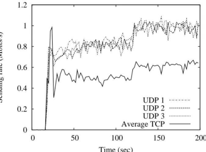
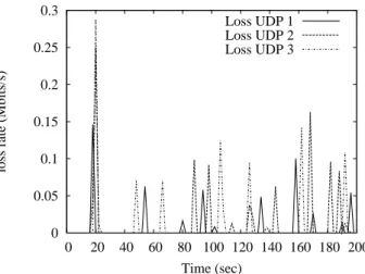
AP have an initial transmission rate of 5.5Mbps and their transmission rates rise to 11Mbps at the relative time 120sec. Between the period t = [18sec, 120sec], Xt as processed by AP equals to 839.9Kbps according to our analytical model, then Xtrises to 991Kbps between t = [120sec, 200sec]. In this scenario, following the pro-posed cross-layered flow control approach, we constrain the UDP sending rate to Xtto avoid MAC layer conges-tion and losses. Figures 15 and 16 represent respectively the sending rate for 3 UDP flows and the average TCP throughput of the 3 TCP flows in default and shaper based scenarios. Figure 17 represents the losses at the MAC layer of each UDP node in default case where mas-sive losses can be observed, while we do not observe any losses at the MAC layer of the UDP mobile nodes in the shaper based scenario.
7.3
Scenario III: Unfairness
improve-ments
This section focuses on the fairness improvement between ACK-clocked (TCP) and Non-ACK-clocked (UDP) flows. We observe that if we only apply the flow control technique previously introduced for MAC layer overflow avoidance, as illustrated in Figure 16, the unfairness is-sue still persists. Indeed, each UDP connection occupies much more bandwidth than each TCP flow. We use the same scenario settings as in section 6.2 while applying our rate equalization mechanism. Our solution consists in bounding the sending rate of each UDP node to Xf air
0 0.5 1 1.5 2 2.5 0 50 100 150 200
Sending rate (Mbit/s)
Time (sec)
Flow 1 Flow 2 Flow 3 Flow 4
Figure 13: Transport Shaper based TFRC sending rate
in order to offer the AP more opportunities of forward-ing ACK packets. As a result, this approach increases the TCP sending rate and significantly reduces unfair-ness issue. In this case, Xf air is processed according to the equalization equation introduced in section 5.2, and equals to 689.5Kbps between t = [18sec; 120sec] and rises up to 826.6Kbps between t = [120sec; 200sec]. We ob-served in Figure 18 that our proposal allows not only avoiding the losses at the MAC layer, but also suppress-ing unfair bandwidth share between flows.
8
Conclusion
We have shown in this paper that a close cross-layer coop-eration can mitigate impedance issues between the differ-ent layers and significantly improve the quality of service delivered to applications in terms of bandwidth delay, losses and jitter. The approach exposed in this paper is quite generic and could be used for several other con-tention based access methods that can potentially entail various communication syndromes such as unfairness or flow control issues. Such a generic approach leverages on an efficient analytical model of the link layer bandwidth estimation, which is based on a set of parameters that can be easily monitored and processed by the end sys-tems or access point. This model coupled with adaptive rate control mechanisms makes it possible to suppress rate maladjustment and unfairness issues. Conversely to other contributions that aim to address these issues from an evolution of the MAC layer features, our pro-posal entails no change to the considered protocols and
0 0.2 0.4 0.6 0.8 1 1.2 1.4 1.6 0 50 100 150 200
Sending rate (Mbit/s)
Time (sec)
IP shaper
Figure 14: IP Shaper scenario: aggregated TFRC send-ing rates
standards (i.e. IEEE 802.11 standard)3, which makes its deployment easier and much more flexible.
We are pushing further this neutral approach for ad-dressing other issues such as the WiFi performance anomaly and the optimization of the WiMax access net-works bandwidth use.
A
Estimation
of
t
jamin
the
TCP/UDP coexisting case
tjam represents the average time spent in collision to send out one frame for each mobile node that make full use of wireless resource (including the K equivalent TCP nodes). If a collision happens, the deferred mobile node can be one of the UDP mobile nodes, one of the TCP node or the access point.Similar to the analysis presented in [3], the mobile node which causes a TCP mobile node (in group Ni
t) deferring can be one of the other (Ni
t−1) mobile nodes in group Ni
t, or a node in other TCP groups, or a node in UDP groups as well as the AP, thus the average time spent in collision for each TCP nodes in group Ni
t is, TT CP i jam = K 1 Nt.(Nt−1)+Nu+1.((N i t − 1). K Nt.T i t + P4,j6=i j=1 N j t.NKt.T j t + P4 i=1(N i u.Tui) + P4 i=1(T i ta. Ni t Nt))
Similarly, the mobile node which causes a UDP mobile node (in group Ni
u) deferring can be one of the other
3
Although this study lays on IEEE 801.11b standard, the ana-lytical model and every derived proposals still hold for faster tech-nologies such as IEEE 801.11g
0 0.2 0.4 0.6 0.8 1 1.2 0 50 100 150 200
Sending rate (Mbits/s)
Time (sec)
UDP 1 UDP 2 UDP 3 Average TCP
Figure 15: Default sending rate
(Ni
u−1) mobile nodes in group Nui, or a node in other UDP groups, or a node in TCP groups as well as the AP, thus the average time spent in collision for each UDP node to send out one frame in group Ni
uis, TjamU DP i = K+N1 u.( P4 i=1N i t. K Nt.T i t + (N i u −1).T i u + P4,j6=i j=1 (Nuj.Tuj) + P4 i=1(Ttai . Nti Nt))
The average time spent in collision for AP is, Tack jam = P4 i=1N i t.NtK.T i t+ P4 i=1(N i u.T i u) K+Nu
Then we can calculate the average time spent in col-lision for the AP and each node to send out one frame is:
tjam = P4i=1TjamT CP i.
Ni t Nt. K Nu+K+1 + P4 i=1TjamU DP i. Ni u Nu+K+1+ T ack jam. 1 Nu+K+1
References
[1] J. Sharony, “Introduction to Wireless MIMO”, Talk of the Communications Society of the IEEE Long Island Section, Nov 2006
[2] J. M. Wilson, “The Next Generation of Wireless LAN Emerges with IEEE 802.11n”, Intel Corpora-tion, White Paper, 2004
[3] Lei Zhang, Patrick Senac, Emmanuel Lochin, Michel Diaz, “Cross-Layer based Congestion Control for WLANs”, ICST QShine, Hong Kong, Jul 2005 [4] M. Handley, S. Floyd, J. Padhye, J. Widmer, “TCP
Friendly Rate Control (TFRC): Protocol Specifica-tion”, Request For Comments 3448, Jan 2003
0 0.2 0.4 0.6 0.8 1 1.2 0 20 40 60 80 100 120 140 160 180 200
Sending rate (Mbit/s)
Time (sec)
UDP 1 UDP 2 UDP 3 Average TCP
Figure 16: Transport shaper based sending rate
[5] OPNET Modeler. www.opnet.com [6] TCPDUMP, http://www.tcpdump.org/
[7] P. Benko and A. Veres, “A Passive Method for Estimating End-to-End TCP Packet Loss”, IEEE Globecom, 2002
[8] S. Pilosof, R. Ramjee, D. Raz, Y. Shavitt and P. Sinha, “Understanding TCP fairness over Wireless LAN”, IEEE Infocom, Mar 2003
[9] C. E. Koksal, H. Kassab, H. Balakrishnan, “An analysis of short-term fairness in wireless media ac-cess protocols (poster)”, Measurement and Model-ing of Computer System, 2000
[10] E. Lopez-Aguilera, M. Heusse, Y. Grunenberger, F. Rousseau, A. Duda, J. Casademont, “An Asymmet-ric Access Point for Solving the Unfairness Problem in WLANs”, IEEE Transactions on Mobile Comput-ing, v.7 n.10, p.1213-1227, Oct 2005
[11] F. Filali, “Wimeter: a bandwidth estimation tool and its assistance to QoS Provisioning in Multiple Hot Spots WLANs”, NEWCOM Technical Dissem-ination Day, Paris, Feb 2007
[12] M. Davis, “A wireless traffic probe for radio resource management and QoS provisioning in IEEE 802.11 WLANs”, ACM international symposium on Model-ing, Analysis and Simulation of Wireless and Mobile Systems, Oct 2004 0 0.05 0.1 0.15 0.2 0.25 0.3 0 20 40 60 80 100 120 140 160 180 200
loss rate (Mbits/s)
Time (sec) Loss UDP 1 Loss UDP 2 Loss UDP 3
Figure 17: Loss in default case
[13] A. Johnsson, B. Melander, M. Bjorkman,
“Band-width Measurement in Wireless Networks”,
Mediterranean Ad Hoc Networking Workshop (Med-Hoc-Net), Jun 2005
[14] K. Lakshminarayanan, V. N. Padmanabhan, J. Pad-hye, “Bandwidth estimation in broadband access networks”, ACM SIGCOMM conference on Internet Measurement, Oct 2004
[15] S. Rangwala, R. Gummadi, R. Govindan, K. Psou-nis, “Interference-aware fair rate control in wireless sensor networks”, ACM SIGCOMM Symposium on Network Architectures, 2006
[16] Y. Li, L. Qiu, Y. Zhang, R. Mahajan, Z. Zhong, G. Deshpande, E. Rozner, “Effects of Interference on Wireless Mesh Networks: Pathologies and a Pre-liminary Solution”, ACM SIGCOMM Workshop on Hot Topics in Networks (HotNets-VI), Atlanta, GA, USA, Nov 2007
[17] Y. Li, L. Qiu, Y. Zhang, R. Mahajan, E. Rozner, “Predictable Performance Optimization for Wireless Networks”, ACM SIGCOMM, Aug 2005
[18] J. Alonso-Zrate, E. Kartsakli, A. Cateura, C. Verik-oukis, and L. Alonso, “A Near-Optimum Cross-Layered Distributed Queuing Protocol for Wireless LAN”, IEEE Communications Magazine, Special Is-sue on MAC protocols for WLAN, vol. 15, no. 1, pp. 48-55, Feb 2005
[19] K. Saravanan, T. Ravichandran, “A Cross-Layer Based High Throughput MAC Protocol for IEEE
0 0.2 0.4 0.6 0.8 1 1.2 0 20 40 60 80 100 120 140 160 180 200
Sending rate (Mbits/s)
Time (sec)
UDP 1 UDP 2 UDP 3 TCP
Figure 18: UDP and average TCP fairness sending rate
802.11 Multihop Adhoc Networks”, European Jour-nal of Scientific Research, vol. 33, no. 4, pp. 575-584, 2009
[20] Hung-Yun Hsieh and Raghupathy Sivakumar, 2001. “Improving Fairness and Throughput in Multi-hop Wireless Networks”, ICN, Colmar, France, Jul 2001 [21] Sarr, C. Chaudet, C. Chelius, G. Lassous, I.G., “A Node-Based Available Bandwidth Evaluation in IEEE 802.11 Ad Hoc Networks”, International Con-ference on Parallel and Distributed Systems, Jul 2005
[22] N. Blefari-Melazzi, A. Detti, A. Ordine, and S. Sal-sano, “Controlling TCP fairness in WLAN access networks using a Rate Limiter approach”, IEEE ISWCS, Siena, Italy, Sep 2005
[23] X. Tian, X. Chen, T. Ideguchi, Y. Fang, “Improv-ing Throughput and Fairness in WLANs through Dynamically Optimizing Backoff”, IEICE Transac-tions on CommunicaTransac-tions, vol. E88-B, no. 11, Nov 2005
[24] Mojtaba Seyedzadegan1, Mohamed Othman,
Shamala Subramaniam, Zuriati Zukarnain, “The TCP Fairness in WLAN: A Review”, IEEE Inter-national Conference on Telecommunication (ICT), Penang, Malaysia, 2007
[25] J. Ha and C.-H. Choi, “TCP Fairness for Uplink and Downlink Flows in WLANs”, IEEE Globecom, San Francisco, 2006
[26] D.J. Leith and P. Clifford, “TCP fairness in IEEE 802.11e WLANS”, IEEE WirelessCom 2005, Hawaii, 2005
[27] M. Bottigliengo, C. Casetti, C.-F. Chiasserini, and M. Meo, “Smart traffic scheduling in IEEE 802.11 WLANs with access point”, IEEE VTC 2003 Fall, Oct 2003
[28] S. Kim, B. Kim, and Y. Fang, “Downlink and uplink resource allocation in IEEE 802.11 wireless LANs”, IEEE Transactions on Vehicular Technology, vol. 54, no. 1, pp. 320327, Jan 2005
[29] Y. Wu, Z. Niu, and J. Zheng, “Study of the tcp up-stream/downstream unfairness issue with per-flow queueing over infrastructure-mode wlans”, Wirless Communications and Mobile Computing, vol. 5, no. 4, pp. 459471, Jun 2005
[30] Y. Wang and B. Bensaou, “Achieving Fairness in IEEE 802.11 DFW MAC with Variable Packet Lengths”, IEEE Globecom, 2001
[31] M. Heusse, F. Rousseau, G. Berger-Sabbatel, and A. Duda, “Performance Anomaly of 802.11b”, IEEE Infocom, 2003
[32] Qiuyan Xia, Mounir Hamdi, “Cross Layer Design for IEEE 802.11 WLANs: Joint Rate Control and Packet Scheduling”, IEEE Conference on Local Computer Networks (LCN), 2005
[33] E.C. Park, D.Y. Kim, H. Kim and C. Choi, “A cross-layer approach for the per-station fairness in TCP over WLANs”, IEEE Transaction on Mobile Com-puting, vol. 7, 2005
[34] Choi, K. Park, and C. Kim, “Cross-layer analysis of rate adaptation, DCF and TCP in multi-rate WLANs”, IEEE Infocom, 2007
[35] Lohier, Stephane and Doudane, Yacine and Pujolle, Guy, “Cross-layer loss differentiation algorithms to improve TCP performance in WLANs”, Springer Telecommunication Systems, vol. 36, no. 1, pp. 61-72, 2007
[35] Deng, Der-Jiunn and Cheng, Rung-Shiang and Chang, Heng-Jia and Lin, Hui-Tang and Chang, Ruay-Shiung, “A cross-layer congestion and con-tention window control scheme for TCP perfor-mance improvement in wireless LANs”, Springer Telecommunication Systems, vol. 42, no. 1, pp. 17-27, 2009