HAL Id: hal-00112274
https://hal.archives-ouvertes.fr/hal-00112274
Submitted on 5 Nov 2018
HAL is a multi-disciplinary open access
archive for the deposit and dissemination of
sci-entific research documents, whether they are
pub-lished or not. The documents may come from
teaching and research institutions in France or
abroad, or from public or private research centers.
L’archive ouverte pluridisciplinaire HAL, est
destinée au dépôt et à la diffusion de documents
scientifiques de niveau recherche, publiés ou non,
émanant des établissements d’enseignement et de
recherche français ou étrangers, des laboratoires
publics ou privés.
On a new methodology for quantitative modeling of
fretting fatigue
Ky Dang Van, Habibou Maitournam
To cite this version:
Ky Dang Van, Habibou Maitournam. On a new methodology for quantitative modeling of fretting
fatigue. D.W. Hoeppner; V. Chandrasekaran; C.B. Elliott. Fretting Fatigue: Current Technologies
and Practices (ASTM STP 1367), American Society for Testing and Materials, pp.538-552, 2000.
�hal-00112274�
Ky Dang Van1 and M. Habibou Maitournam2
On a New Methodology for Quantitative Modeling of Fretting Fatigue
ABSTRACT: A new intrinsic methodology for the prediction of fretting fatigue failure of a structure is presented. It is based, first, on the evaluation of local relevant thermomechanical parameters by new thermoelastoplastic computational methods (direct cyclic method) and, second, on the systematic use of the Dang Van multiaxial high-cycle fatigue criterion. For the validation of this proposal, numerical simulations of fretting fatigue tests on a particular experimental setup considered as a structure are performed. The resulting prediction of the experimental fretting fatigue map in relation to plastic and fatigue material properties is good.
KEYWORDS: fretting fatigue, fretting wear, high-cycle fatigue, numerical methods
Presentation
Fretting is a major problem for industrial components in contact. It is defined as the surface damage induced by small-amplitude oscillatory displacements between metal components in contact. This damage can either be wear or crack nucleation, depending on the prescribed forces or the displacements amplitude. Many experi mental results have been obtained recently. Vingsbo and Soderberg [1] and Vincent et al. [ 2] have established a test methodology based on fretting maps. These maps give the material response fretting map (MRFM) (no damage, crack nucleation or wear) according to the running condition fretting map (RCFM) (partial slip and gross regime). They are very useful for a qualitative understanding of damage phe nomena. However, the results obtained cannot be applied for another configuration
(with different solid geometries and material properties) and consequently they are
1 Professor, Laboratoire de Mecanique des Soli des, Ecole Polytechnique, 91128
Palaiseau, France.
not directly applicable to an industrial component.
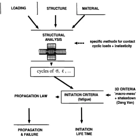
Thus, the use of an intrinsic methodology to predict fretting is essential to be able to transpose laboratory tests results to real applications on mechanical structures. For this purpose, we propose an original approach which can be summarized as shown on the flow chart in Figure 1. Because of problems arising from contacts between solids, many difficulties must be overcome.
LOADING
I
\
STRUCTURE STRUCTURAL ANALYSIS PROPAGATION LAWl
PROPAGATION & FAILURE MATERIAL�--· specific methods for contact
cyclic loads + inelasticity
1
INITIATION LIFE TIME ... 3D CRITERIA 'macro-meso' +shakedown (Dang Van)Figure 1 - Gen eral methodology
• (i) The initial inputs are geometries and nominal loading of the structure. One
must compute the local relevant thermomechanical parameters (temperature, stress, total and plastic strain cycles, their evolutions and eventually their stabilized states) in the regions where fretting cracks may occur. The use of classical finite elements methods is inadequate, because of:
- the type of loading, which is either a moving contact loading or a contact fixed in space but varying in time;
plastic flow which generally occurs during the first cycles even in the case of apparent elastic regime (elastic shakedown);
their flexibility and accuracy are poor despite of very high computational time;
• (ii) the local stress and strain fields are completely tridimensional with no fixed
directions during their evolution. This necessitate the use of fatigue criteria which are able to deal with complex multiaxial loading situations.
To solve the first problem, we have developed a new efficient finite element method. This method, called the direct cyclic method, is based on an original scheme of integration. It is used to evaluate the inelastic state of structures subjected to a cyclic loading. The stabilized state (elastic or plastic shakedown) can directly be obtained.
We then use the multiaxial fatigue criterion proposed by Dang Van [3-5]. Its main attribute is that it can be easily identified by classical fatigue uniaxial labo ratory tests like repeated tension or torsion. This criterion is essentially based on elastic shakedown hypothesis at all scales of materials description (macroscopic and mesoscopic scales).
To validate this proposal we simulate fretting fatigue tests on a particular ex perimental set-up considered as a structure. Numerical predictions are compared to experimental fretting map. This work complete the simulations initialized in two previous papers [ 6-7].
The Computational Problem and Its Main Difficulties
Classical approaches to fretting fatigue are based:
• either on the use of nominal parameters characterizing the loading (for example
the normal force, the amplitude of oscillatory displacement) reported on the usual fretting-map;
• or, more rarely on the evaluation of the resulting local stress cycles under elastic
assumptions.
However, a more careful examination of the problem shows that plastic deformation may occur locally, which changes the local mechanical parameters. Depending on the level of the load, different situations arise:
• purely elastic behaviour for very small loads;
• elastic shakedown: plastic deformation occurs but stabilizes after a certain
number of loading cycles; after this period, the response is purely elastic;
• plastic shakedown: the stabilized cycle is a fixed plastic one; • ratchetting: there is no stabilization of the plastic strain.
These phenomena depend not only on the level of the loading, but also on the geometries of the solids in contact, which influence the local distribution of stress and strain (structural effect). The calculation of this redistribution is generally a very difficult problem due to a great number of nonlinearities related to:
• frictional contact problems with partial or total slip; • inelastic material behaviour;
• moving nature of obstacles, etc.
Nevertheless, one can use some existing computational codes to estimate the contact characteristics (area, pressure and shear distributions, slip or stick zones, etc). These computations are most of the time difficult to perform. However in the case of elastic shakedown, elastic contact computations are sufficient to estimate the former quantities and give a good idea of the running conditions. We shall use these results as limit loading conditions to evaluate the stress and strain fields in the bulk of the solids in order to check the danger of crack initiation.
In a more general situation, it is only possible to simulate some elastoplastic cycles, because the calculations are very lengthy.
In the following, we are more interested in fretting fatigue. To avoid difficult nu merical computations for deriving contact characteristics, a particular contact system corresponding to a cylinder moving on a plane surface is considered. In this case, closed form solutions for elastic behaviour are available. It corresponds for instance to an experimental set-up used by Petiot and al [ 6], and represented in Figure 2. These experiments will be numerically simulated hereafter.
S(t)
t
�
S(t)
P contact force S(t) external fatigue stress
S(t)
b
tOscillating Cylinder on a Half-space: Contact Characteristics
The cylinder considered is in contact with a plane under normal constant com pressive force P and is subjected to repeated alternating tangential force
T(t).
In order to calculate the elastoplastic limit response of the material in fretting, we describe first the loading cycle. Although the aim of the numerical method is to evaluate the inelastic state, the normal pressure and the shear tractions are assumed to be respectively given by the elastic theory of Hertz and the theory of Mindlin [8-9]. This approximation is valid when the stabilized state is elastic (elastic shakedown). In the case of plastic shakedown, the contact pressures are in fact modified during the cycles but the hypothesis of elastic contact pressures is maintained.The contact width is assumed to be sufficiently small in comparison with the dimensions of the two bodies. The constant normal pressure p(x) and the contact area are assumed to be given by Hertz theory:
�
p(x) =Poy
1--;;}where p0 is the maximum normal pressure and a the contact half width. The tangen
tial force
T(t)
describes an alternate loading cycle of amplitude2Tmax·
Two cases are studied:• partial slip for
T max
< 11P, • full slip forTmax
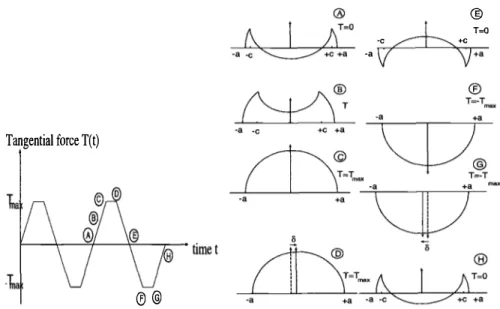
= flP.The description of the loading cycles and the corresponding shear distributions are respectively represented on Figures 3 and 4. For more details, one can refer to Maouche et al. [?J, and Hills and Nowell [10]. The cycles of loading just described are prescribed as external forces for the determination of the stabilized state with the new numerical method which is now recalled.
Direct Cyclic Method
The direct cyclic method allows the direct determination of the asymptotic re sponse (i.e. stabilized mechanical state) of a structure subjected to a general cyclic loading without an incremental treatment of the whole loading history.
The principle of the finite element method is based on the two following proce dures: (i) large time incremental method; (ii) research of the solution in the space of periodic responses, which means that we seek directly for mechanical fields (stresses, strains, plastic strains, etc) which are cyclic, (i.e. which have the same value at the end of the loading cycle as at the beginning of the cycle).
This method can be applied to any kind of elastoplastic constitutive equation; it can predict elastic or plastic shakedown regimes, and even ratchetting.
The details and the applicability of the method were discussed in previous pa pers [ 9, 11] on two dimensional examples. In these examples, the surface pressure distributions shown on Figures 3 and 4 are used. The considered loading parame ters are
Po/k
= 3.5, J.l =0.3, Tmax/
P =0.25
andPo/k
=2.,
J.l = 0.6,Tmax/
P = 0.6;Tangential force T(t) ® ® ® ©
6
-c[j
T-O rnax +Cmax --a -c \0:0?l "Z7
+C+a
-a
-c mu: +Cmax+8
Figure 3 -Loadin g cycle with no ful l slidin g an d the correspon din g shear traction
distributions {7 j Tangential force T(t) ®@ ®
�
T=O -c +C-a v
\j+a
Figure 4 -Loadin g cycle with ful l slidin g an d the correspon din g shear traction
20 r----.. -6Q.2.5
�
�
p( 1'\
r �
!\'
f"#"' ...rr
!!"" � "'l!" ' -- �N
�
V
l'-
� """V
1\
I
� O'xx � O'xz\
J
<>--tl Oyy 1>----fi(Jzz """' - Jl5 r--1.5 -0.5 0.5 1.5Normalized absciss x/a
�<>-.._ le----e- I--2.5
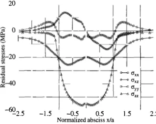
Figure 5 -Residual stresses at the surface in the case of stick regime
60 "2 20 p... 6 <fJ <1l <fJ <fJ <1l -20 tl ";J :::3 :g <fJ <1l -60 � -100 -2.5
r
1\I
'
�1\
���··"'
... , � ' � 0xx\
1
- O'xz\
t - ·-cryy A----t:,. 0zz\
I
"'
�/
-1.5 -0.5 0.5 1.5Normalized absciss x/a 2.5
k
= 159 MPa is the shear resistance of the considered linear kinematic hardeningelastic-plastic von Mises material (Young's modulus: 207GPa, Poisson's coefficient: 0.3, Hardening modulus: 45 GPa). They correspond respectively to stick slip regime with elastic shakedown and gross slip regime with plastic shakedown happens. In Figures 5 and 6 we show the final residual stresses (i.e. stresses remaining after the removal of the loading, once the stabilized state is reached) obtained. In all cases, the CPU time is much lower than by using incremental method.
The Fatigue Criterion
The used high-cycle fatigue criterion was initially proposed by Dang Van [ 3-5]. It is based on a multiscale approach in which it is assumed that elastic shakedown happens before crack initiation. In this approach, two scales are considered: (i) a macroscopic scale characterized by an arbitrary elementary volume surrounding the point where fatigue analysis is made and representing for instance an element of finite element mesh; it is the usual scale considered by engineers; (ii) a mesoscopic scale corresponding to subdivision of the previous volume; the stress tensor at this scale results from the macroscopic one and the local residual stresses due to local inelastic deformation.
Thanks to the shakedown assumption at the local scale, it is possible to estimate the local stress cycle from the macroscopic stress cycle. The criteria is then expressed as an inequality related to the mesoscopic stresses at all instants t of the cycle, so that damaging loading can be precisely characterized. The criterion used is expressed as:
mp.x{T(t) + ap(t)}:::;
b
where T(t) and p(t) are the instantaneous mesoscopic shear stress and hydrostatic stress, a and
b
are material constants, which can be determined by two different classical fatigue tests.Practically, the fatigue resistance of a structure is checked point by point, using two ways.
• The first one is the representation of the loading path (p(t), T(t)) at each point
in the (p, T) diagram. In this diagram, two constants a and
b
define a safety domain (no fatigue cracks) which is the region below the line (7 + ap =b).
If the loading path at each point is entirely in the safety domain, there is no fatigue crack, otherwise fatigue damage occurs.
• The second one is the evaluation at each point of the quantity a: = maxt{ ( T(t)
-ap(t)-
b)/b}.
Positive value of a: means occurrence of fatigue crack.These two representations are used in the section devoted to numerical analysis of fretting to interpret in terms of fatigue, the results of simulations of a particular fretting setup. The experimental study is presented in the next section.
Experimental Study of Fretting
In this section, we present the experimental results obtained by Petiot and al [6]. The experimental setup used is presented in Figure 2. Two cylindrical fretting pads
(diameter 10 mm) are clamped against the two surfaces of a flat uniaxial fatigue specimen tested under constant amplitude loading at a frequency of 20 Hz. The pads are made of 100C6 steel and the fatigue specimen is made of 3Cr-MoV steel. The mechanical properties are given below:
Material 3Cr-MoV 100C6 Yield strength MPa 980 1700 Tensile strength MP a 1140 2000 Young modulus MP a 215 210 Hardness Hv 360 62 The prescribed oscillation between the pads are linked to the prescribed oscillatory fatigue stress S(t) in the specimen. For a maximum stress Smax=500 MPa, the amplitude of displacement, 6, is 0.55 J-Lm. The flexible beams are equipped with strain gauge in order to measure the clamping force P between pads and specimen and the friction force related to the displacements accommodation. The variations of the tangential force T(t) are recorded for each fatigue cycle and plotted as function of fretting fatigue stress S(t) (fretting fatigue loops). By varying the operating parameters (P, Smax), three regimes are established:
• Stick regime: Fretting fatigue loops keep a non evolutionary closed shape.
Loops are quite linear during the test. The macroscopic displacement between the contacting surfaces is mainly accommodated by elastic deformation in the near surface of the two components. No damage (wear or crack nucleation) appears during the 107 cycles of the test.
• Mixed stick-slip regime: Loops present an elliptical closed shape. There is
partial slip and fatigue crack nucleation observed at the edges of the contact.
• Gross slip regime: Loops present a trapezoidal shape. Full slip occurs between
the two contacting surfaces. In this regime, particles detachment is observed. The different regimes are obtained for different varying parameters (P, Smax) summarized in the map shown in Figure 7.
Our aim in the next section is to establish a numerical material response fretting fatigue map and to compare it with the experimental one presented in Figure 7. The principle of this comparison is the following: for each point of Figure 7, we use the corresponding experimental data (P, Smax, Tmax) to perform numerical calculation of the stabilized stress (or plastic strain) cycle and then we apply the fatigue criterion to predict crack occurrence.
Numerical Analysis and Prediction of Wear and Crack Nucleation
This section is devoted to the numerical simulation of the experimental setup presented in the previous section. The prediction of damage mechanisms shown in Figure 7 requires first the calculation of the stress history in the stabilized state. Secondly, Dang Van multiaxial fatigue criterion is applied if the stabilized state is elastic shakedown.
The finite element method (direct cyclic method) described previously is used here to simulate the set-up and to calculate the stresses history in the stabilized state.
180
160 Mixed stick and slip
Stick regime regime
�140 4 •
, I
'-Q..l20
"' No damage Crack initiation
�100
..:; • • {:,
.�
80 0�
60 Gross slip regime.!:! \,) 40
20 Partick detachment
0 0 100 200 J:JO 400 500 600 700 800
Maximum fatigue stress SllliJX (MPa)
Figure 7- Frettin g fatigue map (MRFM)
The specimen is modeled as a half space subjected to a constant normal force P and a varying tangential force T(t) and a fatigue stress S(t) varying linearly with T(t). The material is elastoplastic with a kinematical hardening (hardening modulus C=30 GPa) and with properties given previously.
Four simulations are performed; they correspond to the following four experi-mental points reported on the Material Response Fretting Map (Figure 7):
• P=140 N, Smax=350 MPa and Tmax=53 N (the biggest filled triangle), • P=lOO N and Smax=400 MPa (the empty triangle),
• P=lOO N, Smax=600 MPa and Tmax=80 N (the biggest empty square), • P=80 N, Smax=500 MPa and Tmax=64 N (the empty circle).
P and Smax are the prescribed parameters and Tmax is measured in the test. The first two points are in the stick regime; the response of material is most of the time purely elastic and no damage is observed. The third point is in the mixed stick-slip regime where crack nucleation is observed. The fourth one is the gross slip regime where wear is observed.
Numerical Calculation of Stress and Strain cycles
The loading parameters (P, Smax, Tmax) are used to analytically determine the contact characteristics (length, pressures distributions as shown in Figures 3 and 4). FEM analysis, using the direct cyclic method, is then performed to calculate the stabilized mechanical cycle. The mesh is refined under the contact surface as shown in Figure 8. In this figure, the zone with rectangular elements has a width of 2a, a varying from 50 !Jm to 80 !Jm in our present applications.
In the case of loading in gross slip regime, plastic shakedown is obtained numeri cally. This regime is represented by a closed cycle of plastic deformation and leads to
Figure 8 -Refin ed mesh under the contact surface (total width of this zon e betw een 100 J.Lm an d 200 J.Lm depen din g on the load)
8 ! a ! a
���\
-- - ---3 2 1 =0.00 2 = 4.22 E-3 3 = 8.64 E-3 4 = 1.29 E-2 5=1.72E-2 6 = 2.16 E-2 7 = 2.58 E-2Figure 9 - Contours of equivalent plastic strain in the case of full slidin g regime, at the instant when the tan gential force is zero
low cycle fatigue. Experimentally, wear is observed in this regime. Thus, a connec tion between wear and the low cycle fatigue properties can be made, confirming the works of Kim and Ludema [12] and Johnson [13]. The numerical method used gives the plastic strain amplitude in the stabilized state. Figure 9 shows the contours of equivalent plastic strain in this case.
Numerical Prediction of Fatigue
Since the calculated response of material is respectively purely elastic and elastic shakedown in stick regime and mixed stick-slip regime, high cycle fatigue is con cerned. The stress cycle through the contact is multiaxial. Dang Van multiaxial fatigue crack nucleation criterion is used to predict fatigue cracks. For each loading case (a point of Figure 7, corresponding to given values of P, Smax and Tmax), the stabilized stress cycle calculated as described in the previous section is used to de termine at each point of the structure, the mesoscopic loading path consisting of the mesoscopic shear T(t) and the hydrostatic pressure p(t). At each point, this loading path is then compared to the fatigue properties of the material (material line) ob tained from torsion t and bending f fatigue tests (t=380 MPa and /=594 MPa for 30NCD16 steel). The most critical point is located at the surface on the edge of the contact. The most critical loading path ( T, p) for each case is plotted in Dang Van's fatigue diagram shown in Figure 10. In the stick regime, the two triangles of Figure
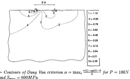
7 we simulate (P=140 N, Smax=350 MPa, Tmax=53 N and P=lOO N, Smax=400 MPa) give loading path which are beneath the fatigue line material; so, no damage occurs as observed experimentally. In mixed stick-slip regime, the simulated square of Figure 7 (P=100 N, Smax=600 MPa and Tmax=80 N) leads to a loading path which intersects the fatigue line material, meaning crack nucleation. The contours of the Dang Van criterion o: = maxt
T(t)-
t
t)-bare plotted on figure 11. A positive value of o: means crack initiation.
All the obtained numerical results are brought together in Figure 10; a result obtained by Petiot and al [ 6] who used a different simulation for the calculation of the stress cycles is added. The numerical predictions of crack initiation are in total agreement with the experimental observations reported in Figure 7.
Conclusion
Quantitative prediction of risk of fretting fatigue on a structure is of prime im portance for many structures. However, this problem is so difficult that until now, no predictive method is available. The problem has been studied by engineers em pirically; long and expensive experimental tests have to be performed to be sure to
avoid fretting fatigue.
We propose a new methodology for studying the fretting phenomena based first on the evaluation of the local mechanical parameters by efficent inelastic numerical methods, and second on the use of multiaxial fatigue criterion which can be easily identified by simple tests, independant of contact phenomena.
per-600G=�====================� - Material line 500 � 6,400 ... 5 fii 300
-�
�200�
100... Stick regime P=l40 N and Smax=350 MPa � Stick regime P=IOO N and Smax=400 MPa --Mixed stick-slip regime P=l40 N an d Smax=500 MP
o----a Mixed regime P= 140N and Smax::=600MPa (Petiot et )
D-O Mixed stick-slip regime P=IOO N an d Smax=600 MP
�00 -200 0 200 400 600
Hydrostatic pressure p (MPa)
Figure 10 -Loading paths in Dang Van's diagram in stick regime and mixed
stick-slip regime: safe paths are below the material line
2a 2 = -0.95 3 = -0.79 4 = -0.62 5 = -0.46 6 = -0.29 7=-0.13 B = 0.04
Figure 11 -Contours of Dang Van criterion a = max
t T(t)-
a:(
t)-b for P = lOONformed by Petiot and al. [ 6], and compare the numerical predictions to the ex perimental results. By this method, we are able to distinguish the three differents regimes observed experimentally:
• Stick regime: it corresponds to pure elasticity and no damage occurs;
• Mixed stick-slip regime; in this case, the regime is elastic or elastic shakedown;
fatigue is observed; the used multiaxial fatigue criterion predicts correctly crack initiation;
• Gross slip regime: wear is observed.
To obtain results, we must evaluate the stabilized state (elastic or plastic shakedown regimes) which is obtained directly by an original scheme of integration, if the contact characteristics (i.e. normal and tangential stress on the surface at any time of the cycle) are known. For real applications with general contact geometry, this last requirement remains a difficult problems, which is not straightforward. However, we have verified that in our example, elastic shakedown hypothesis corresponding to fatigue regime is valid; it is then possible to use some existing classical FEM codes to estimate these contact characteristics. Some applications to real industrial structures are currently being studied by this new methodology.
References
[1] Vingsbo, 0. and Soderberg S., "On Fretting Maps", Wear, Vol. 126, 1988, pp. 131-147.
[2] Vincent, L., Berthier, Y., and Godet, M., "Testing Methods in Fretting Fa tigue: a Critical Appraisal", Standardisation of Fretting Fatigue Test Methods
and Equipment, ASTM ST P 1159, M. Helmi Attia and R.B. Waterhouse, Eds., American Society for Testing and Materials, Philadelphia, 1992, pp. 33-48. [3] Dang Van, K., Griveau, B., and Message, 0., "On a New Multiaxial Fatigue
Limit Criterion: T heory and Application", biaxial and multiaxial fatigue, M.W. Brown and K. Miller, Eds., EGF Publication 3, 1982, pp.479-496.
[4] Dang Van, K., "Macro-Micro Approach in High-Cycle Multiaxial Fatigue", Ad vances in multiaxial fatigue, ASTM ST P 1991, D.L. McDowell and R. Ellis, Eds., American Society for testing and Materials, Philadelphia, 1993, pp. 120-130. [5] Dang Van, K., "Introduction to Fatigue Analysis in Mechanical Design by the
Multiscale Approach", High-Cycle Metal Fatigue in the Context of Mechanical Des ign, K. Dang Van and I. Papadoupoulos, Eds, CISM Courses and Lectures No. 392, 1999, Springer-Verlag, pp. 57-88.
[6] Petiot, C., Vincent, L., Dang Van, K., Maouche, N., Foulquier, J., and Journet, B., "An Analysis of Fretting-Fatigue Failure Combined with Numerical Calcu lations to Predict Crack Nucleation", Wear, Vol. 181-183, 1995, pp. 101-111.
[7] Maouche, N., Maitournam, H.M., and Dang Van, K., "On a New Method of Evaluation of the Inelastic State due to Moving Contacts", Wear, Vol. 203-204, 1997 pp. 139-147.
[8] Mindlin, R.D., Compliance of Elastic Bodies in Contact, J.Appl.Mech, Vol.16, 1949, pp. 259-268.
[9] Johnson, K.L., Contact Mechanics, Cambridge University Press, 1985.
[10] Hills, D.A., and Nowell, D., Mechanics of frettin g fatigue, Kluwer Academic Publishers, 1994.
[11] Maitournam, M.H., "Finite Elements Applications Numerical Tools and Spe cific Fatigue Problems", High-Cycle Metal Fatigue in the Context of Mechan ical Design, K. Dang Van and I. Papadoupoulos, Eds., CISM Courses and Lectures No. 392, 1999, Springer-Verlag, pp. 169-187.
[12] Kim, K., and Ludema, K.C., "A Correlation Between Low Cycle Fatigue and Scuffing Properties of 4340 Steel", Wear, Vol. 117, 1995 pp. 617-621.
[13] Johnson, K.L., "Contact Mechanics and Wear of Metals", Wear, Vol. 190, 1995 pp. 162-170.