HAL Id: hal-01667194
https://hal.archives-ouvertes.fr/hal-01667194
Submitted on 8 Nov 2018
HAL is a multi-disciplinary open access
archive for the deposit and dissemination of
sci-entific research documents, whether they are
pub-lished or not. The documents may come from
teaching and research institutions in France or
abroad, or from public or private research centers.
L’archive ouverte pluridisciplinaire HAL, est
destinée au dépôt et à la diffusion de documents
scientifiques de niveau recherche, publiés ou non,
émanant des établissements d’enseignement et de
recherche français ou étrangers, des laboratoires
publics ou privés.
Talc grinding in an opposed air jet mill: start-up,
product quality and production rate optimization
L Godet-morand, Alain Chamayou, John A. Dodds
To cite this version:
L Godet-morand, Alain Chamayou, John A. Dodds. Talc grinding in an opposed air jet mill:
start-up, product quality and production rate optimization. Powder Technology, Elsevier, 2002, 128 (2-3),
pp.306-313. �10.1016/S0032-5910(02)00172-9�. �hal-01667194�
Talc grinding in an opposed air jet mill: start-up, product quality and
production rate optimization
Laurence Godet-Morand, Alain Chamayou, John Dodds *
Laboratoire de Ge´nie des Proce´de´s des Solides Divise´s, UMR CNRS 2392, Ecole des Mines Albi-Carmaux, Campus Jarlard, 13, route de Teillet, 81013 Albi Cedex 09, France
Abstract
We present a study of talc grinding in an Alpine 100 AFG opposed air jet mill with an inline laser granulometer. The conditions for steady state operation have been determined from continuous grinding experiments and show that overloading occurs above a critical value of feed rate classifier resulting in unstable product size distribution. For each rotation speed of the classifier, there is an optimum feed rate, which gives the finest product, thus fixing a maximum reduction ratio. A linear relation exists between this ratio and the rotation speed of the classifier. The use of liquid grinding aids have been studied and showed they can result in an increase in the production rate but can also lead to a coarser product.
Keywords: Talc; Grinding; Classification; Optimum fineness; Particle size distribution; Grinding aids
1. Introduction
Talc is a mineral used in many industrial applications such as paper, paints, polymers, cosmetics and pharmaceuticals, and is usually produced as a fine powder by autogeneous milling so as to avoid contamination. In many cases, air jet mills, such as the Alpine AFG series, in which concurrent jets of compressed air create the active grinding zone, are used for talc production. Many studies in the literature have been concerned with the determination of breakage parameters for population balance models. However, some studies concern the influence of operating parameters (e.g. grinding air pressure, classification speed, feed rate) on the ground product. Among previous works carried out on these mills, Gommeren[1], who studied polymer grinding in a spiral jet mill and also in a 200 and 400 AFG opposed air jet mills, may be quoted. His interest was mainly in modeling the overall grinding classification process in a spiral jet mill. Berthiaux and Dodds [2] modeled the overall grinding-classification process of hydrargillite in an Alpine 100 AFG opposed air jet mill.
In our study, continuous grinding experiments were per-formed to determine influence of classification speed and feed rate on the stability of the grinding-classification proc-ess, product fineness and grinding rate.
The operating conditions for stable grinding classification have also been used as the basis for evaluating the action of several liquid grinding aids. These grinding additives may act in several ways. Fuerstenau[3]reviewed the action of liquid grinding aids in dry grinding processes and showed that they can improve particle flowability in the active grinding zone, weaken the particles leading to easier breakage and also prevent finer particles from agglomerating, thus allowing them to leave the active grinding zone more easily. Para-masivam et al. [4 – 6] have demonstrated the efficiency of liquid grinding aids on dry ball milling of calcite. Using Jenike flow factor tests, they showed that liquid additives decrease the cohesion of calcite particles and improve their flowability index, thus leading to a finer particle size distri-bution of the ground product. However, no work has dealt with improvements in jet milling by the use of grinding aids.
2. Experimental
Continuous grinding experiments have been performed with an Alpine 100 AFG opposed jet mill equipped with a 50
* Corresponding author. Tel.: +33-5-6349-3122; fax: +33-5-6349-3025.
E-mail addresses: [email protected] (L. Godet-Morand), [email protected] (J. Dodds).
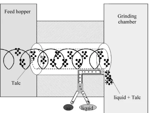
ATP-forced vortex classifier and an Insitec inline laser diffraction particle sizer. Details of the grinding chamber and classifier are shown inFig. 1. Particles contained in a hopper are continuously fed by a screw feeder into the grinding chamber where they are ground at the meeting point of the three concurrent air jets formed by 2-mm-diameter ceramic nozzles supplied with compressed air at 6 bar. After grinding, particles are carried by airflow up to the turbo classifier, which removes the fine particles and returns the coarser ones to the grinding zone. The fine particles are collected in a container below a cyclone. An Inline Insitec laser granulometer located between the classifier outlet and the cyclone inlet gives a continuous measurement of particle size distribution during grinding process (cf.Fig. 2). Previous work[7]showed that accurate particle size distribution was obtained using a flow derivation from the main flow allowing
redispersion by air injection. The talc used in this study was provided by Luzenac Europe from their Trimouns quarry. The particle size distribution determined by dry laser dif-fraction using a Malvern Mastersizer 2000S apparatus has a median size of 12.5Am and a span of 2.49.
Continuous grinding experiments have been run using four different classification speeds: 7000, 9000, 11,000 and 13,000 rpm with feed rates from 20 g/min up to the classifier flooding value. In addition, three different liquid additives have been tested by direct feeding in the grinding chamber using a peristaltic pump (cf. Fig. 3). Additive A has a feed rate of 2.2 ml/min. Additive B is a solid dispersed in liquid additive A and used at a concentration of 0.14 % per mass of talc. Additive C is used at a concentration of 2% per volume in A. In summary, three additives were used: A, A + B and A + C.
The particle size distribution of the product at the classifier outlet is measured by the an EPCS Insitec inline laser granulometer. Product samples were also taken and, after sample division were analysed in the laboratory by dry and liquid laser diffraction using a Malvern Mastersizer 2000S, a Micromeritics Sedigraph 5100 and a Coulter Counter Multi-sizer II. The particle size distribution of the talc held up in the mill chamber is measured in the same way with the same laboratory particle size measurement apparatus.
3. Steady state operation
The establishment of a steady operating regime starting from an initially empty mill involves the accumulation of particles in the grinding zone until a constant hold-up is reached. As the mill is not continually weighed, one way to detect the steady regime is to stop the experiment and weigh the amount of particles in the mill chamber. How-ever, the inline laser granulometer, which gives continuous measurement of product particle size distribution and a measure of the production rate by obscuration of the laser Fig. 1. 100 AFG opposed air jet mill. Details of grinding chamber and 50
ATP-forced vortex classifier.
beam, also allows detection of the steady state regime. For example,Fig. 4 shows the variation of the median particle size of the product as a function of grinding time indicating that the steady state is established faster for a feed rate of 70 g/min (about 4 min) than for 51 g/min (about 5 min) or 22 g/min (about 7 min). In practice, 15 min were allowed even though for the lowest feed rates, only 7 min were enough to establish steady operation from the point of view of the median size. It was also confirmed that the full particle size distribution was also stabilized at the same time as the median size.
The inline laser granulometer gives not only particle size distributions but also the laser transmission, which is directly related to the talc production rate. The higher the laser transmission is, the lower the production rate. Mon-itoring the laser transmission also indicates when the steady state regime is reached from the point of view of produc-tion rate. For example, Fig. 5 shows that the production rate becomes stable more quickly than the median size regime: about 2.5 min at 70 g/min, 4 min for 51 g/min and about 6 min at 22 g/min. In every case, less time is required than the 15 min, which were allowed in practice. It should Fig. 3. System of introduction of the liquid additive in the grinding chamber.
Fig. 4. Median size steady state establishment at 11,000 rpm for 22 g/min (5), 51 g/min (o) and 70 g/min (+).
Fig. 5. Laser transmission steady state establishment at 11,000 rpm for 22 g/ min (5), 51 g/min (o) and 70 g/min (+).
be pointed out that even if the product flow rate has reached its steady regime, the product particle size distri-bution may not be stable. Even if the flow rates are stable in each step of the process, the grinding process needs longer time to reach its steady regime. In practice, it is necessary to ensure that product particle size distribution is stable before assuming that the process is in true steady state regime.
4. Continuous grinding experiments 4.1. Influence of grinding parameters
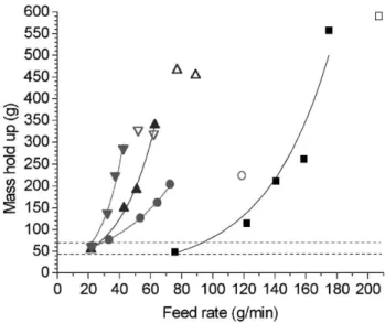
Continuous grinding experiments give information on the mass held up in the mill chamber as a function of the feed rate for different classification speeds (cf.Fig. 6). For each classification speed, there exists a critical value of feed rate above which the classifier becomes flooded. In fact, when the amount of particles in the mill chamber is too high, the classifier becomes obstructed, power con-sumption of the classifier motor increases and rotation speed decreases. As a consequence, the particle size dis-tribution at the classifier outlet becomes coarser and wider, the production rate increases leading to a reduction in the particle hold-up in the mill chamber. The obstruction of the classifier work is then reduced until the amount of particles in the mill chamber increases again to result in another obstruction of the classifier. In these conditions, an unsteady cycling regime of particle size distribution and production rate is observed.
At the lowest value of feed rate, a common minimum value of talc hold-up exists for each classification speed. This mass is about 50 g of talc and may correspond to a
dead volume in various parts of the grinding chamber or to the mass of talc required to start autogeneous grinding. 4.2. Optimum fineness
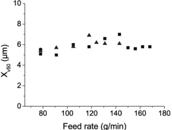
The particle size distribution measured by the Insitec inline laser granulometer in continuous grinding experi-ments gives a measurement of the median size of the talc product as a function of the feed rate.Fig. 7shows that there is an optimum value for the feed rate for a minimum value of median size at each classification speed.
Fig. 6shows that at a given classification speed, a given feed rate corresponds to a given hold-up of talc in the mill
Fig. 6. Mass held in the mill at different classifier speed: 7000 rpm stable (n); 7000 rpm unsteady (5); 9000 rpm stable (
.
); 9000 rpm unsteady (o); 11,000 rpm stable (E); 11,000, rpm unsteady (4); 13,000 rpm stable (z
); 13,000 rpm unsteady (5).Fig. 7. Median size of talc production measured by Insitec as a function of the feed rate for 7000 rpm (n), 9000 rpm (
.
), 11,000 rpm (E) and 13,000 rpm (z
).Fig. 8. Median size of talc production measured by Insitec as a function of the mass of talc held up in the mill chamber for 7000 rpm (n), 9000 rpm (
.
), 11,000 rpm (E) and 13,000 rpm (z
).chamber.Fig. 8. shows also that there is an optimum mass of talc held up in the mill giving the minimum value of median size for each classification speed. Optimum mass hold-up for every classification speed seems to be similar in each case, i.e. at between 200 and 250 g of talc.
Low feed rates lead to low hold-up, resulting in a low collision probability and thus in a poor breakage probability. At high feed rates, but below the classifier flooding value, there is a high hold-up in the mill chamber, which tends to reduce air jet penetration in the particle bed. Under these conditions, the low specific kinetic energy per particle gives a low breakage probability. Hence, there exists an optimum value of mass hold-up in the mill chamber giving the highest breakage probability and the finest ground product at the
outlet of the classifier. It is therefore possible to choose operating conditions (feed rate and classifier speed) that will give a hold-up resulting in the finest talc product from the grinding classification process. However, the optimum feed rate value may be different from the maximum feed rate that the mill can take. From an industrial point of view, there is a competition between fineness and production rate.
It is also possible to plot similar graphs as those onFigs. 7 and 8, but using particle size distributions measured with other particle size methods, namely Malvern Mastersizer 2000S in dry and liquid mode, Micromeritics Sedigraph 5100 and Coulter Counter Multisizer II. All these size measurement methods lead to the same conclusions as the Insitec data about optimum fineness.
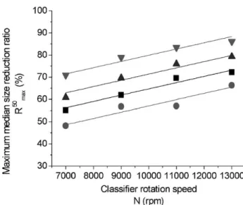
Fig. 9. Maximum median size reduction ratio as a function of classifier rotation speed. (
z
) Sedigraph data. (E) Liquid dispersion Malvern Mastersizer 2000S. (n) Coulter Counter Multisizer II. (.
) Dry dispersion Malvern Mastersizer 2000S.Fig. 10. Engine intensity of classifier at 7000 rpm during continuous grinding tests with no additive (
.
), with additive A (n), with additive A + B (E) and with additive A + C (z
).Fig. 11. Engine intensity of classifier at 11,000 rpm during continuous grinding tests with no additive (
.
), with additive A (n), with additive A + B (E) and with additive A + C (z
).Fig. 12. Xv10 as a function of feed rate at 7000 rpm during continuous
grinding tests with no additive (
.
), with additive A (n) and with additive A + B (E).From the minimum value of the median size for each classification speed, a maximum reduction ratio of the median size of talc particles can be determined (Eq. (1)).
R50max¼ 100 X0 v50" Xv50N X0 v50 ð1Þ From all particle size distribution measurement methods, the maximum median size reduction ratio (Rmax50 ) has a linear
relation with the classifier rotation speed (N) (cf. Fig. 9) (Eq. (2)).
R50max¼ 2:815 % 10"3% N þ C ð2Þ
The constant 2.815 seems to be an intrinsic parameter of the grinding classification process independent of the particle
size distribution measurement method, whereas the constant C is a parameter that depends on the size measurement method.
5. Talc grinding with additives
5.1. Effect of grinding aids on the talc production rate In the absence of additives, the maximum feed rate leading to classifier flooding, as indicated by an increase in the classifier motor amperage, is about 270 g/min at 7000 rpm and about 78 g/min at 11,000 rpm. In experiments on continuous operation of the air jet mill, three additives lead to the following improvements in the production rate: at 7000 rpm (cf.Fig. 10), additive A allows a feed rate increase of 15 Fig. 13. Xv50 as a function of feed rate at 7000 rpm during continuous
grinding tests with no additive (
.
), with additive A (n) and with additive A + B (E).Fig. 14. Xv90 as a function of feed rate at 7000 rpm during continuous
grinding tests with no additive (
.
), with additive A (n) and with additive A + B (E).Fig. 15. Xv10as a function of feed rate at 11,000 rpm during continuous
grinding tests with no additive (
.
), with additive A (n) and with additive A + B (E).Fig. 16. Xv50as a function of feed rate at 11,000 rpm during continuous
grinding tests with no additive (
.
), with additive A (n) and with additive A + B (E).%, additive A + B a 19% increase; at 11,000 rpm (cf.Fig. 11), additive A gives a feed rate increase of 88% and A + B, one of 83%; additive A + C does not improve the feed rate and/or the production rate of talc.
Additives A and A + B have almost the same effect on the increase of talc production rate.
5.2. Effect of grinding aids on product particle size distribution
The use of additives A and A + B at 7000 rpm decreases the overall talc particle size distribution by about 20%. Indeed, Xv10 (cf. Fig. 12), Xv50(cf. Fig. 13) and Xv90 (cf.
Fig. 14) decrease in a similar fashion through the use of A and A + B. However, adding B to A does not reduce the talc product particle size distribution at 7000 rpm.
The effect of grinding aids on talc product particle size distribution at classifier speeds of 11,000 rpm is different from results at 7000 rpm. The values of Xv10(cf. Fig. 15)
and Xv50 (cf. Fig. 16) of talc ground in the presence of
additives are higher than those without additive, whereas Xv90 (cf. Fig. 17) is generally lower. At 11,000 rpm,
additives A and B reduce the coarse particle sizes but have no effect on the finer talc particles. There is also almost no difference between the results using A and A + B. This difference may be due to the fact that grinding aids may act preferentially on the flowability of the particles [5 – 7]
rather than on grindability itself. For this reason, in the mill used here, which includes a 50 ATP-forced vortex pneu-matic classifier, the additive may have a greater effect on the classification process than on the grinding.
6. Conclusions
The Insitec laser inline granulometer gives a very good indication of the establishment of the steady regime of talc
grinding in an Alpine 100 AFG opposed air jet mill. It also shows that the product rate reaches its steady state value before the product particle size distribution becomes stable. In industrial practice, about 10 – 15 min are normally allowed for the onset of steady state operation for this type of jet mill. Use of inline laser granulometer shows that the time required is in fact less than 10 min.
Continuous grinding experiments have been performed at different classifier rotation speeds and feed rates. For each classification speed, there is a critical value of feed rate above which the classifier becomes flooded, thus leading to coarser product particle size distributions and unstable operation.
For all classifier rotation speeds, there exists an opti-mum value of feed rate giving the finest talc product. This optimum value of feed rate corresponds to a given mass hold-up of talc in the mill chamber (about 200 – 250 g). This optimum value may be explained by the competition between collision probability and breakage efficiency. At low talc hold-up, the number of collisions is low leading to a low breakage probability. At high talc hold-up in the mill, the number of collisions is high, but the kinetic energy per particle is low leading to poor breakage probability. The optimum value of hold-up lies between these two limits.
The maximum reduction ratio in the median size of talc particles produced by the opposed air jet mill follows a linear relation with the classifier rotation speed for all five particle size measurement methods used in this study. This implies that for any given size measurement method and given classification speed, it is possible to determine the median size of talc particles that can be obtained from this jet mill.
Three different grinding additives have been tested and found to improve production rate and also the product particle size distribution. Additive A alone seems to be adequate for this purpose since additive A and the mixture A + B have almost the same effect on talc production rate and size reduction. Additive C has no real influence on production rate. However, a difference is found in the behavior of the additives for operation at 7000 and 11,000 rpm. As proposed by Godet-Morand et al.[7], it would be interesting to have a measurement of the product flowability index both with and without additive to study the influence of these grinding aids on particle transport in opposed jet mills.
Nomenclature
R50max Maximum reduction ratio in median particle size
(%) Xv50
0
Volume median size of feed particles before grinding (Am)
Xv50N Volume median size of product particles at
classification speed N (Am) N Classifier speed (rpm) Xv50 Volume median size (Am)
Fig. 17. Xv90as a function of feed rate at 11,000 rpm during continuous
grinding tests with no additive (
.
), with additive A (n) and with additive A + B (E).Xv10 10% volume quantile smaller than
Xv90 90% volume quantile smaller than
References
[1] H.J.C. Gommeren, Study of closed circuit jet mill plant using on-line particle size measurement, PhD Thesis, Delft, 1997.
[2] H. Berthiaux, J.A. Dodds, Modeling fine grinding in a fluidized bed opposed jet mill: Part II. Continuous grinding, Powder Technol. 106 (1999) 78 – 87.
[3] D.W. Fuerstenau, Grinding aids, Kona 13 (1995) 5 – 18.
[4] R. Paramasivam, R. Vedaraman, Effects of the physical properties of liquid additives on dry grinding, Powder Technol. 70 (1992) 43 – 50. [5] R. Paramasivam, R. Vedaraman, Effect of fatty acid additives on the
material flow properties of dry grinding, Powder Technol. 77 (1993) 69 – 78.
[6] P.B. Rajendran Nair, R. Paramasivam, Effect of grinding aids on the time-flow characteristics of the ground product from batch ball mill, Powder Technol. 101 (1999) 31 – 42.
[7] L. Godet-Morand, A. Chamayou, J.A. Dodds, Granulome´trie en ligne sur un broyeur a` jets d’air oppose´s de type Alpine 100 AFG, Re´cents Progre`s en Ge´nie des Proce´de´s, Mate´riaux Divise´s et Poudres en Industries Alimentaires, Lavoisier, Paris, No. 63, vol. 13, 1999, pp. 183 – 189.