HAL Id: hal-03203091
https://hal.archives-ouvertes.fr/hal-03203091
Submitted on 20 Apr 2021
HAL is a multi-disciplinary open access
archive for the deposit and dissemination of
sci-entific research documents, whether they are
pub-lished or not. The documents may come from
teaching and research institutions in France or
abroad, or from public or private research centers.
L’archive ouverte pluridisciplinaire HAL, est
destinée au dépôt et à la diffusion de documents
scientifiques de niveau recherche, publiés ou non,
émanant des établissements d’enseignement et de
recherche français ou étrangers, des laboratoires
publics ou privés.
Combining STPA with SysML Modeling
Fellipe Guilherme Rey de Souza, Juliana De Melo Bezerra, Celso Hirata,
Pierre De Saqui-Sannes, Ludovic Apvrille
To cite this version:
Fellipe Guilherme Rey de Souza, Juliana De Melo Bezerra, Celso Hirata, Pierre De Saqui-Sannes,
Ludovic Apvrille. Combining STPA with SysML Modeling. The 14th annual IEEE International
Systems Conference (SysCon 2020), Apr 2020, Montréal (virtual), Canada. �hal-03203091�
an author's https://oatao.univ-toulouse.fr/25232
https://doi.org/10.1109/SysCon47679.2020.9275867
Rey de Souza, Fellipe Guilherme and Melo Bezerra, Juliana de and Hirata, Celso and Saqui-Sannes, Pierre de and Apvrille, Ludovic Combining STPA with SysML Modeling. (2020) In: The 14th annual IEEE International Systems Conference (SysCon 2020), 20 April 2020 - 23 April 2020 (Montréal, Canada).
Combining STPA with SysML Modeling
Fellipe Guilherme Rey de Souza
Department of Computer Science Instituto Tecnol´ogico de Aeron´autica
S˜ao Jos´e dos Campos, Brazil [email protected]
Juliana de Melo Bezerra
Department of Computer Science Instituto Tecnol´ogico de Aeron´autica
S˜ao Jos´e dos Campos, Brazil [email protected]
Celso Massaki Hirata
Department of Computer Science Instituto Tecnol´ogico de Aeron´autica
S˜ao Jos´e dos Campos, Brazil [email protected]
Pierre de Saqui-Sannes
ISAE-SUPAERO, Universit´e de Toulouse, France [email protected]
Ludovic Apvrille
LTCI
LTCI, T´el´ecom Paris, Institut polytechnique de Paris Sophia Antipolis, France
Abstract—System-Theoretic Process Analysis (STPA) is a tech-nique, based on System-Theoretic Accident Model and Process (STAMP), to identify hazardous control actions, loss scenarios, and safety requirements. STPA is considered a rather complex technique and lacks formalism, but there exists a growing interest in using STPA in certifications of safety-critical systems devel-opment. SysML is a modeling language for systems engineering. It enables representing models for analysis, design, verification, and validation of systems. In particular, the free software TTool and the model-checker UPPAAL enable formal verification of SysML models. This paper proposes a method that combines STPA and SysML modeling activities in order to allow simulation and formal verification of systems’ models. An automatic door system serves as example to illustrate the effectiveness of the proposed approach.
Index Terms—STPA, SysML, method, safety analysis, formal verification.
I. INTRODUCTION
System-Theoretic Accident Model and Processes (STAMP) is an accident causality model, based on systems theory [1]. System-Theoretic Process Analysis (STPA) [2] is a technique, based on STAMP, to identify hazardous control actions, loss scenarios, and safety requirements. STPA is considered a rather complex technique since it requires a different analysis perspective compared to other hazard analysis techniques, such as Fault Tree Analysis [3] and Failure Mode and Effects Anal-ysis [4]. STPA derives an analAnal-ysis in terms of control actions, feed-backs, and other interactions. There exists a growing interest in using STPA because STPA has been claimed to be able to identify more loss scenarios and safety requirements due to hazards in the concept stage of the development life cycle [2]. However, STPA lacks formalism [5] to be employed with verification tools.
The Systems Modeling Language (SysML) has been adopted by the Object Management Group (OMG) as a stan-dard [6]. Engineering organizations employ SysML along with methods and tools throughout the development life cycle of systems. However, it remains unclear how these developers can take advantage of using both STPA and SysML technology,
CNPq (grant numbers 403921/2016-3 and 306186/2018-7)
including methods and tools. In that context, a prime objective of this paper is to help answering the following question: “How can a systems engineer benefit from STPA in identifying loss scenarios and safety requirements, and using SysML to support the validation and verification of systems’ properties?”.
This paper proposes a method that combines and takes ad-vantages of STPA with SysML modeling activities, including simulation and formal verification of systems models. STPA provides directives to identify safety requirements of a system, based on investigations of the system control structure (in fact a system model). SysML can help to represent such model and to analyze it, mainly using simulation to validate safety requirements, and formal verification of safety properties of interest. Moreover, using SysML diagrams, we can structure STPA analysis by clarifying and clearly specifying the assump-tions, the requirements, the boundaries of the system, and the interactions between its components.
This paper is organized as follows. Section II briefly presents STPA. Section III characterizes SysML and associates it with a tool and a method. Section IV surveys related work. Section V proposes a method that combines STPA and SysML modeling. It also discusses the case study (a door control system). Section VI summarizes contributions, discusses the proposed approach and outlines future work.
II. STPA
Systems-Theoretic Accident Model and Processes (STAMP) [1] is based on three concepts: (i) a Control Structure, which is a hierarchical representation of the system under analysis where upper-level components impose constraints on lower-level components; (ii) a Process Model, namely a model of the process being controlled; and (iii) Safety Constraints, namely restrictions that the system components must satisfy to assure safety.
System-Theoretic Process Analysis (STPA) [2] is a tech-nique based on STAMP for accident analysis. STPA has four main steps. (1) Define the Purpose of the Analysis aims to identify losses, hazards, and the system boundary. (2) Model the Control Structure captures functional relationships and
interactions using STAMP. (3) Identify Unsafe Control Actions identifies the potentially Unsafe Control Actions (UCA) and associated safety constraints. For each Control Action (CA), namely a command usually issued towards the controlled process, the analyst must identify cases where a CA can be hazardous. (4) Identify Loss Scenarios reveals potential causes of issuing UCAs. For each UCA identified earlier, the goal is to discover scenarios and associated causal factors that can lead the system to a hazardous state, and to generate safety requirements. In general, each unsafe control action can be inverted to define a safety constraint. Safety constraints and requirements assist designers in eliminating or mitigating the potential causes of unsafe control and the occurrence of hazards.
III. SYSML MODELING
Recognized as an enabling technology for Model-Based Systems Engineering, SysML is a graphical modeling lan-guage that applies to a broad variety of systems. The SysML standard at OMG [6] states that “SysML supports the specifi-cation, analysis, design, verifispecifi-cation, and validation of systems that include hardware, software, data, personnel, procedures, and facilities.” The SysML standard [6] defines a notation, not the way of using it. Therefore, SysML needs to be associated with a method supported by one or several tools.
There are many tools that describe models in SysML, part of them further enabling model simulation and verification. Examples of tools include Cameo Systems Modeler [7], En-treprise Architect [8], Modelio [9], Rhapsody [10], SCADE Architect [11], Papyrus [12], and TTool [13]. Since SysML is not a method, and given a MBSE approach relies on a triptych (language, tools, method), one needs to associate a method with the tools used to develop the SysML models. A SysML tool is usually associated with a method that can be tuned to meet the method already in use in the company or institution where the tool is being deployed.
Among previously listed tools, TTool is a free and open-source toolkit to edit UML and SysML diagrams. It also enables SysML models simulation and formal verification against safety (using UPPAAL [21]), security, and perfor-mance properties. TTool supports AVATAR [14], a customized SysML for the modeling and formal verification of real-time embedded systems. For simplicity, the remainder of the paper will use ‘SysML’ and not ‘AVATAR’. The method associated with TTool includes the following phases: Model Assumptions Expression(that describes the set of assumptions that make the model valid [15]), Requirement Capture (that intends to elicit user, stakeholder, and system requirements), Analysis (that is use-case driven. For instance, applying use-case, sequence and activity diagrams), Design (that describes the systems architecture in the form of a block diagram and gives each block a behavior modeled by a state machine diagram), and Model Simulation and Verification (that allow checking the system model against design errors and verifying whether the requirements are satisfied or not).
IV. RELATED WORK
Dakwat and Villani [16] propose a method combining STPA and the UPPAAL Model Checker in order to provide a formal representation of the system under analysis and the threats identified by STPA. They argue that their combination improves the knowledge about the system under design and the consistence of the design changes proposed to tackle the safety constraints identified in STPA. They neither use SysML modeling nor employ a development method.
P´etin et al. [17] propose the combination of SysML and for-mal methods to capture and structure safety requirements and model-checking techniques for formal verification purposes. However, they do not use STPA and therefore miss taking advantage of its benefits.
Krauss et al. [18] present the approach that integrates STPA with tool-chains based on SysML/UML modeling tool Enterprise Architect (EA). They discuss the risks related to the integration of STPA and introduce the software tool SAHRA to help in the integration. There is no intent for formal verification.
Hurley and Wankel [19] present an approach for designing for safety using STPA with Model Based Systems Engineering (MBSE). The approach uses safety constraints (for identified hazards) to model the state machine diagram and verify its behavior. However, their approach does not enable formal verification.
V. METHOD TO COMBINE STPA AND SYSML MODELING ACTIVITIES
The proposed method shall follow the activities depicted by Fig. 1. We group the activities into two sets: STPA and SysML: the upper and lower parts refer to the use of SysML, while the part in the middle refers to STPA activities. In order to describe and illustrate the use of the method, we consider an example of a door system. The door system has a controller that opens the door when sensing the presence of a person. Otherwise, it closes the door. The controller also opens the door if an emergency signal is received. Below, we explain the activities included into the method.
A. Model Assumptions
Fig. 2 depicts the modeling assumption diagram developed to focus on the logic of the controller, leaving apart the set-up and shutdown of the controller, as well as its maintenance. Also, the controller is supposed to be failure-free. And so are the devices the controller is connected to.
B. Capture Requirements
This activity identifies the requirements for the system and its components. Fig. 3 depicts a requirement diagram developed for the model of the door. Due to space limitations, not all the requirement diagrams are shown here. Below, we enumerate a few more requirements. In relation to the controller, the requirements are as follows: the system issues an ‘open door’ command when either sensing the presence of person or receiving the emergency signal; and the system
Fig. 1. Method that combines STPA and SysML modeling activities
Fig. 2. Modeling Assumptions Diagram
issues a ‘close door’ command when sensing the absence of person close to the door.
With respect to sensors, the requirements are as follows:
• The system shall sense the presence of persons close to
the door,
• The system shall sense the absence of persons close to
the door,
• The system shall detect the position of the door (closed,
opening, open, closing), and
• The system shall receive the emergency signal from other systems.
For the actuator, the requirement is as follows: the system shall open or close the door according to the command issued by the controller.
Fig. 3. Main Requirement Diagram
C. Identify losses and hazards
A loss involves something valuable to stakeholders. Losses may include a loss of human life, human injury, property or equipment damage, and environmental damage. Hazard is a system state or set of conditions that, together with a particular set of worst-case environmental conditions, will lead to a loss [2]. In STPA, it is required to associate hazards to losses.
In the activity Identify losses and hazards, we identify the following losses (accidents) for the door system: “Person being hit by a closing door” (L1) and “Person being trapped inside the building” (L2). L1 and L2 are identifiers of the losses. We identify the following hazards: “Door closes on a person in the doorway” (H1) and “Person unable to exit during an emergency” (H2). The hazard H1 leads to the loss L1 while H2 leads to L2.
This STPA activity has some common tasks with the two previously shown SysML activities, Model assumptions and Capture requirements. The assumptions and system require-ments are also identified in this STPA activity. We opt to leave the identifications in SysML activities because the assumptions and requirements are specified using SysML diagrams, allow-ing a better integration.
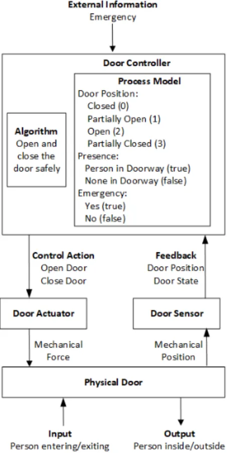
D. Model the control structure
A hierarchical control structure is a system model that is composed of feedback control loops. An effective control structure enforces constraints on the behavior of the system. Constraints avoid hazardous states of the system. In a control structure, the controller provides control actions to control some process and to enforce constraints on the behavior of the controlled process.
The control algorithm represents the controllers decision-making process. It determines the control actions to provide. Controllers also have process models that are used by algo-rithms to make decisions. Process models include states of the process being controlled or other relevant aspects of the
Fig. 4. Control structure of door system.
system or the environment. Process models are updated in part by feedback used to observe the controlled process. In Fig. 4, we illustrate the result of the activity Model the control structure for the door system.
E. Identify unsafe control actions
An Unsafe Control Action is a control action that, in a particular context and worst-case environment, will lead to a hazard. There are four ways a control action can be unsafe: (i) not providing the control action leads to a hazard; (ii) providing the control action leads to a hazard; (iii) providing a potentially safe control action but too early, too late, or in the wrong order; and (iv) the control action lasts too long or is stopped too soon (for continuous control actions). In the activity Identify unsafe control actions, the unsafe control actions identified for the door system are shown in Table I (in the first column).
F. Identify loss scenarios
A loss scenario describes the causal factors that can lead to the unsafe control actions and to hazards. Two types of loss scenarios must be considered: (i) “Why would Unsafe Control Actions occur?” and (ii) “Why would control actions be improperly executed or not executed, leading to hazards?”. In the activity Identify loss scenarios, we will consider only the control algorithm logic. For this, we assume that actuators, sensors, links to issue control actions and receive feedback,
Fig. 5. Use case diagram of the door system
controller hardware, and communications with other systems are reliable. We also assume that the controlled process be-haves reliably. In this situation, the control actions are properly executed always. Therefore, the occurrence of unsafe control actions is due to an inadequate control algorithm.
In Table I (in the second column), we show the requirements that apply to the control algorithm of the door system. We may note that safety requirement SR3 is a more specific than SR1, so SR1 could be removed. SR3 is SR1 with time restriction. We are going to keep SR1 for the purpose of analysis. G. Perform analysis
In terms of system analysis, use case diagrams and sequence diagrams can be employed. In terms of design, the architecture and behaviors are respectively defined by a block diagram and state machines diagrams. Here we use a use-case diagram.
Fig. 5 depicts the use case diagram for the door system. It shows the actors (sensors and actuators) and the use cases to process the signals outgoing from the sensors. The use cases ProcessPresence and ProcessEmergency include Issue-ControlAction. The benefit of this diagram is to confirm if components and interactions that compose the system were correctly identified in the designed control structure.
H. Perform design
The block diagram in Fig. 6 models the architecture of the door system. We use SysML blocks to model system blocks (including DoorController, DoorActuator, DoorSensor, and PhysicalDoor), and to model environment inputs (including EmergencySensor and PresenceSensor). Inside each block in the block diagram, there is a state machine diagram that establishes the behavior of the block. Asynchronous con-nection channels between pairs of blocks enable conveying the signals that must be transmitted, as described here. The PresenceSensor block shall send presenceSignal (indicating that there is a person in the doorway) or noPresenceSignal (otherwise) values to DoorController. The PresenceSensor block also register its presenceState with true (with a person) and false (without a person).
The EmergencySensor block shall send emergenceSignal to DoorController in case of emergency. The EmergencySensor block also keeps emergenceState with true (when emergency) or false (with no emergency). The DoorSensor block shall
TABLE I
UNSAFECONTROLACTIONS, ASSOCIATEDSAFETYCONSTRAINTS ANDASSOCIATEDSAFETYREQUIREMENTS TO THECONTROLALGORITHM
Unsafe Control Actions Safety constraints Safety requirements to the control algorithm
Door controller does not provide open door command when emergency.
Not Provided: In an emergency, the door always must open.
SR1: Door controller shall provide open door command when emergency
Door controller does not provide open door command when a person is on the doorway.
Not Provided: The door never must close if there is a person on the doorway.
SR2: Door controller shall provide open door command when person is on the doorway. Door controller provides open door command
late when emergency.
Wrong Time or Order: Whenever there is an emergency, the door must be opened for evac-uation in time.
SR3: Door controller shall provide open door command immediately when emergency. Door controller stopped open door command
too soon when emergency.
Too Soon: Whenever there is an emergency, the door should be opened completely.
None. The controller has issued the command to the actuator, but the actuator has not followed adequately.
Door controller provides close door command when a person is on the doorway.
Provided: Sensors should prevent the door from closing when there is a person on the doorway.
SR4: Door controller shall not provide close door command when person is on the doorway. Door controller provides close door command
when emergency.
Provided: During an emergency, the door con-troller must not close the door.
SR5: Door controller shall not provide close door command when emergency.
Door commanded closed too early, before per-son finishes entering/exiting
Wrong Time or Order: Sensors should prevent the door from closing when there is a person on the doorway.
SR6: Door controller provides close door com-mand after 5 seconds after opening.
receive doorState from PhysicalDoor and send to DoorCon-troller. The door can have four states: closed (0), opening (1), open (2), and closing (3). The Actuator block receives openDoor or closeDoor commands from DoorController and sends to PhysicalDoor.
The block diagram is globally similar to the control structure diagram shown earlier (in Fig. 4). In fact, both provide the required information to design the block diagram using SysML. However, there exist few differences between both representations. In the control structure, the emergency signal comes from the environment. In the block diagram, there is a specific block to indicate emergency, called EmergencySen-sor, which waits for 15 seconds to detect an emergency. It was a particular implementation decision, aiming to simulate emergency. However other simulation design could be made.
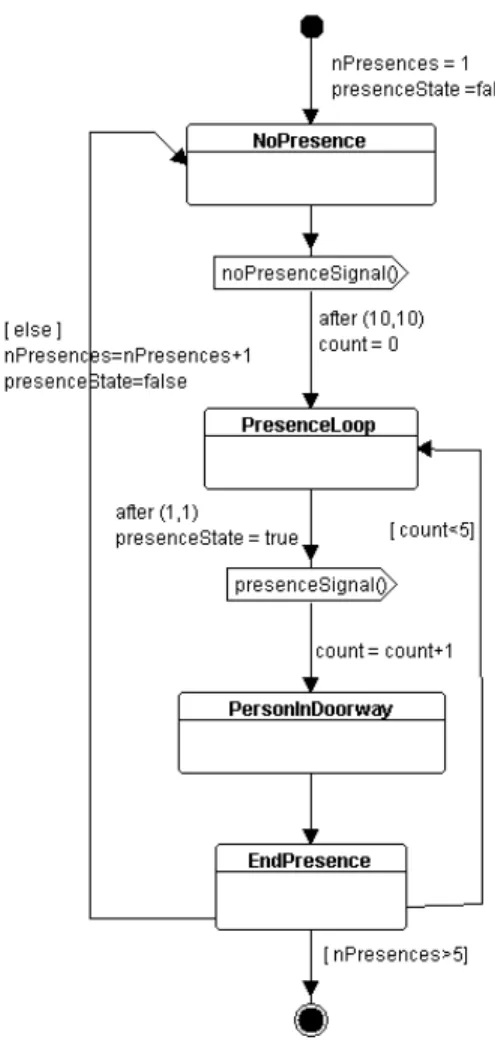
Another difference is that the input (person entering/exiting) and output (person inside/outside) of the control structure is somehow modelled by the block PresenceSensor (in Fig. 7). The PresenceSensor block is responsible for detecting the presence and absence of a person close to the door. It is modeled as a process that continuously detects no presence (absence) of a person, waits for 10 seconds, detects five consecutive presences, and later repeats this behavior five times. Again the PresenceSensor implementation reflects a particular choice, so other simulation design could include presence randomness.
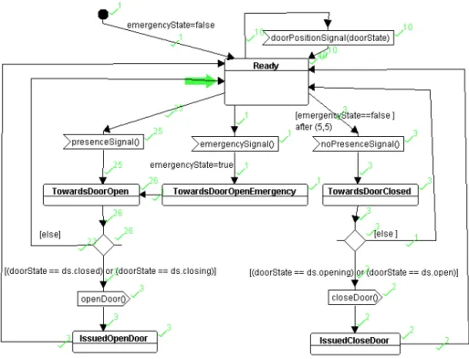
The state machine diagrams of the controlled process (in this case, the door itself), the actuator, and the door position sensor are straightforward and are not shown here. Fig. 8 presents the state machine diagram of the door controller, which is the focus of the design. Both the block diagram and the state machine diagrams have to satisfy the system and safety requirements shown in Table I. DoorController can receive presenceSignal and then go towards opening the door (in fact sending the openDoor command only if the door is closed or closing). The DoorController can receive emergenceSignal and go towards opening the door due to
Fig. 7. The state machine of the presence sensor
for receiving the presenceSignal. The DoorController can receive noPresenceSignal and then go towards closing the door (in fact sending the closeDoor command only if the door is opening or open).
I. Perform simulation and formal verification
In the Perform simulation and formal verification activity, we firstly explore the simulation feature of TTool. Running the simulation, we can see in the DoorController state machine that many execution paths have been performed thanks to the green check quotes (see Fig. 8). To better understand the different execution paths, TTool also supports step-by-step simulation and breakpoints.
Simulation aids us to check whether all paths of the model are being explored. In the door system, firstly we observed that the IssuedCloseDoor state was not being reached. Investigating the model, we verified that there was no situation where we need to close a door already open or opening. Indeed, before this situation happens, the system detects an emergency. We then updated the EmergencySensor to inform emergency after 50 seconds (incrementing the previously set value).
Regarding formal verification, we use TTool and the model checker UPPAAL [21]. A first interesting possibility is to check the system for reachability and liveness properties.
Reachability of an action p means there exists at least one execution trace in which p is executed. Liveness of p means that in all possible execution traces, p is executed [21]. By investigating reachability and liveness of the state Towards-DoorOpenEmergency of DoorController, we found that both properties are satisfied. If we change EmergencySensor to not send any emergence signal, both properties are no longer satisfied. Thus, it is another way to verify whether the control being designed is consistent.
TTool also helps identifying deadlock situations. The “Searching for absence of deadlock” situations property is not satisfied. Through the generated Reachability Graph, TTool indicates cases of deadlock. Analyzing the model, we observe that we designed EmergencySensor and PresenceSensor with end points. If we eliminate these end points (by allowing an infinite loop in the last state), the “Searching for absence of deadlock situations” property is now satisfied. It shows that the deadlocks were due to the finalization of execution of components, and not because of a modeling problem in DoorController.
With respect to the safety requirements indicated in Table I, we can specify the properties to be formally verified. The associated safety properties (known as safety pragmas in TTool) are shown in Fig. 9, as well as their results: a green mark indicates that the property is satisfied, whilst a red mark shows that the property is not satisfied. In all cases, we check the “leads to” property. Given the two actions p and q, the expression “p leads to q” (or p → q) means that q will always be executed at least once after p.
For “SR1: Door controller shall provide open
door command when emergency” requirement,
we write the “EmergencySensor.SentEmergency →
DoorController.TowardsDoorOpenEmergency” property. The property is satisfied, confirming the SR1 requirement. The SR3 requirement is similar to SR1. In order to verify SR3 in TTool, we need to consider a deadline for ‘immediately’, for instance less than x units of time.
One recommendation here is that, in order to use the leads to operator (also denoted as →), we need to consider those states in the state machine diagrams which represent the desired situations to be verified. For the SR1 requirement, the states are SentEmergency and TowardsDoorOpenEmergency. This directive serves as a modeling guideline during the Perform design activity. It also confirms the importance of interactive cycles between the Perform design activity and the Perform simulation and formal verificationactivity.
For the “SR2: Door controller shall provide open door command when a person is on the doorway” requirement, we firstly use the “PresenceSensor.PersonInDoorway → DoorController.IssuedOpenDoor” property. The property is not satisfied. Observing DoorController, we verify that the door can be already open or opening, and then it is not necessary to provide open door again. We then argue that the SR2 requirement needs to be updated to consider the door states.
Fig. 8. State machine diagram of the door controller with simulation results
Fig. 9. Safety properties of the door system
DoorController.TowardsDoorOpen” property for SR2 require-ment. In this case, we consider that a person in the doorway will make the door controller let the door open (issuing a open door command just if necessary). The property is true, confirming SR2 requirement. We observe that, when applying the proposed method, we can need to perform improvements in the safety requirements (defined in Identify unsafe control actions activity), due to the challenge of establishing safety properties to be formally verified.
Considering the “SR4: Door controller shall not provide close door command when person is on the
doorway” requirement, we establish the following
property: “PresenceSensor.presenceState==true →
PhysicalDoor.doorState==2”. It means that whenever PresenceSensor detects a person, the door will be open (represented by state numbered as 2). In this way, the DoorController does not issue any ‘close’ command, since the door is kept open. The property is satisfied, which confirms SR4 requirement is met.
For “SR5: Door controller shall not provide close
door command when emergency” requirement, we
state the “EmergencySensor.emergencyState==true →
PhysicalDoor.doorState==2” property. The property is structured similarly to the one associated with SR4 requirement. It means that whenever we have an emergency, the door will be open. In this way, the DoorController does not issue any close command, since the door is kept open. The property is then satisfied, confirming SR5 requirement is met.
For “SR6: Door controller provides the close door command after 5 seconds after opening”, a simple inspection in the state machine diagram of DoorController indicates that it takes 5 seconds before issuing the closeDoor command.
VI. CONCLUDINGREMARKS
Combining STPA with SysML modeling in a development method enables to develop and verify the system in a more systematic manner, taking advantage of the integration of TTool and UPPAAL. With the approach, we are able to translate the STPA safety requirements into properties to be verified by UPPAAL from TTool. A simple example illustrates the use of our approach. We consider that the approach is effective in finding the safety requirements and verifying if the designed SysML models satisfy these requirements or not. We believe that the approach is a pragmatic way to employ formal verification for safety-critical system development.
Thanks to our proposed method, we identified two chal-lenges. The first one is related to SysML modeling and more specifically to the elaboration of the state machine diagrams of the components. We constructed the diagrams by attempting to satisfy the functional requirements. It is a try and error approach. Later we verify if the state machine diagrams satisfy
the STPA safety requirements or not. In doing so, we come across the our second challenge, which is to map the STPA safety requirements into properties in TTool/UPPAAL. We believe that some research is needed in helping to systematize these tasks.
Rinehart et al. [20] point out that many academic research papers involve small toy example cases whereas practitioner reports tend to focus on lessons learned and experience of large systems, without presenting how the complexity is handled. This is a presentation dilemma. Here, we used an illustrative system to better detail the method. So, the method can be applied consistently considering more complex scenarios. We argue that both simulation and formal verification can gain even more relevance in case of complex scenarios.
In case of complex scenarios, we could face some real-world issues. Although the proposed method is easy to understand and apply, the size of a real scenario can demand high effort in modeling and analysis. Diagrams can then be difficult to generate and maintain; while many formal properties can be needed. A possible approach is to decide which part of the system is really critical, and apply the method only to this part. In this way. the analysis is more focused on what is needed.
In this paper, the links, actuators, controlled process, and sensors are assumed to be reliable. The example needs to be adjusted to encompass degraded situations (unreliable links or components). In this case, the step Identify loss scenarios should consider scenarios of degraded situations, which would result into additional safety requirements. If we consider the occurrence of faults such as the error of presence detection of the sensor, then the safety requirements associated to presence detection error of the sensor shall be identified and met. For instance, the requirement can be “DoorSensor shall have a reliability of 99.9%”, which can be addressed with sensor redundancy. Therefore, it is interesting to use the proposed method to systems that have more specific requirements related to loss scenarios.
Another avenue to explore deals with the automation of the method. Souza et al. [22] show that STPA can be systematized and automated. They developed a tool (called WebSTAMP), which aids analysts throughout the analysis process in a more automated and comprehensive way, and it aims to be a collaborative tool. We believe that is possible to combine WebSTAMP and TTool, having our method as foundation. This is part of a broader project that aims to provide users of STPA and TTool with a methodological assistant that would guide newcomers to the language, the tool, and the method. The idea is to take advantage of the STPA analysis already supported by WebSTAMP. We can add steps in WebSTAMP to elaborate SysML diagrams in TTool, according to our proposed method. So WebSTAMP would have access to such diagrams. We can also implement a way to analysts define in WebSTAMP a formal property for each identified safety requirement. An integration of WebSTAMP with TTool, can then support the formal verification, by adding properties to the model and submitting the model to UPPAAL analysis.
REFERENCES
[1] N. Leveson, Engineering a Safer World: Systems Thinking Applied to Safety,. MIT Press, 2011.
[2] N. Leveson and J. Thomas, STPA Handbook, 2018, https://psas.scripts.mit.edu/home/, last accessed 2019/5/6.
[3] C. Ericson II. “Fault tree analysis - a history”, Proceedings of the 17th International System Safety Conference, August, 1999.
[4] MIL-STD-1629A, Military Standard - Procedures for Performing a Failure Mode, Effects and Criticality Analysis, Department of Defense, Washington, DC, November 1980.
[5] E. Harkleroad, A. Vela, and J. Kuchar, Review of Systems-Theoretic Process Analysis (STPA) Method and Results to Support NextGen Concept Assessment and Validation, Project Report ATC-427, MIT Lincoln Laboratory, Washington, DC, October 2013.
[6] SysML.org, OMG Systems Modeling Language Version 1.5, 2017, https://sysml.org, last accessed 2019/7/1.
[7] O. Casse, SysML in Action with Cameo Systems Modeler, ISTE, November 2017.
[8] Entreprise Architect, https://sparxsystems.com/, last accessed 2019/7/9. [9] Modelio,
https://www.modeliosoft.com/en/modules/sysml-architect.html, last accessed 2019/7/9.
[10] Rhapsody, https://www.ibm.com/us-en/marketplace/systems-design-rhapsody, last accessed 2019/7/10.
[11] T. Le Sergent, A. Le Guennec, S. Gerard, Y. Tanguy, and F. Terrier, “Using SCADE System for the Design and Integration of Critical Systems,” SAE Technical Paper 2011-01-2577, 2011.
[12] S. Grard, C. Dumoulin, P. Tessier, and B. Selic, “Papyrus: A UML2 tool for domain-specific language modeling”, Model-Based Engineering of Embedded Real-Time Systems (MBEERTS 2007), pp. 361-368. [13] TTool, http://ttool.telecom-paristech.fr/, last accessed 2019/7/9. [14] G. Pedroza, D. Knorreck, and L. Apvrille, “AVATAR: a SysML
environ-ment for the formal verification of safety and security properties”, The 11th IEEE Conference on Distributed Systems and New Technologies, Paris, France, 2011.
[15] P. de Saqui-Sannes and L. Apvrille, “Making modeling assumptions an explicit part of real-time systems models”, 8th European Congress on Embedded Real Time Software and Systems (ERTS). Toulouse, France, January 2016.
[16] A. Dakwat and E. Villani, “System safety assessment based on STPA and model checking”, Safety Science, Vol.109, Nov. 2018, pp 130-143. [17] J. P´etin, D. Evrot, G. Morel, and P. Lamy. “Combining SysML and formal methods for safety requirements verification”. 22nd International Conference on Software Systems Engineering and their Applications, Dec 2010, Paris, France.
[18] S. Krauss, M. Rejzek, and C. Hilbes, Tool qualification considerations for tools supporting STPA, Procedia Engineering 128 (2015 ) 15-24. 3rd European STAMP Workshop, STAMP EU 2015.
[19] M. Hurley and J. Wankel, “Safety guided design using STPA and model based system engineering (MBSTPA)”, 2019 STAMP Workshop, last accessed on 2019/7/2. http://psas.scripts.mit.edu/home/2019-stamp-workshop-presentations/
[20] D. Rinehart, J. Knight, and J. Rowanhill, “Understanding what it means for assurance cases to work”. NASA/CR2017-219582, (2017). [21] G. Behrmann, A. David, and K. G. Larsen. “A Tutorial on UPPAAL”
Formal Methods for the Design of Real-Time Systems, 2004. [22] F. Souza, D. Pereira, R. Pagliares, S. Nadjm-Tehrani, and C. Hirata,
WebSTAMP: a web application for STPA & STPA-Sec, International Cross-industry Safety Conference (ICSC) - European STAMP Workshop & Conference (ESWC). Vol 273. 10.1051/matecconf/201927302010.