HAL Id: hal-01002828
https://hal.archives-ouvertes.fr/hal-01002828
Submitted on 28 Mar 2021
HAL is a multi-disciplinary open access
archive for the deposit and dissemination of
sci-entific research documents, whether they are
pub-lished or not. The documents may come from
teaching and research institutions in France or
abroad, or from public or private research centers.
L’archive ouverte pluridisciplinaire HAL, est
destinée au dépôt et à la diffusion de documents
scientifiques de niveau recherche, publiés ou non,
émanant des établissements d’enseignement et de
recherche français ou étrangers, des laboratoires
publics ou privés.
A reconfigurable multi-standard ASIP-based turbo
decoder for an efficient dynamic reconfiguration in a
multi-ASIP
Vianney Lapotre, Purushotham Murugappa Velayuthan, Guy Gogniat, Amer
Baghdadi, Jean-Philippe Diguet, Jean-Noël Bazin, Michael Hubner
To cite this version:
Vianney Lapotre, Purushotham Murugappa Velayuthan, Guy Gogniat, Amer Baghdadi, Jean-Philippe
Diguet, et al.. A reconfigurable multi-standard ASIP-based turbo decoder for an efficient dynamic
reconfiguration in a multi-ASIP. ISVLSI 2013 : IEEE Computer Society Annual Symposium on VLSI,
Aug 2013, Natal, Brazil. �10.1109/ISVLSI.2013.6654620�. �hal-01002828�
A reconfigurable multi-standard ASIP-based turbo decoder for an efficient dynamic
reconfiguration in a multi-ASIP context
Vianney Lapotre∗, Purushotham Murugappa†, Guy Gogniat∗, Amer Baghdadi†, Jean-Philippe Diguet∗,
Jean-No¨el Bazin†and Michael H¨ubner‡
∗
Univ. Bretagne Sud, UMR6285, Lab-STICC, F56100 Lorient, France. Email: [email protected]
†Telecom Bretagne, UMR6285, Lab-STICC, F29200 Brest, France. Email: [email protected]
‡
Rurh-Universit¨at Bochum, ESIT, Bochum, Germany. Email: [email protected]
Abstract—The emergence of many wireless standards is introducing the need of flexible multi-standard baseband receivers. To address this issue and to face the increasing demand of higher throughput for new greedy applications on mobile devices recent works propose multi-ASIP platforms for decoding algorithms. Furthermore dynamic evolution of communication parameters combined with the reduction of latency between two data frames imposes the need for an efficient reconfiguration management of such systems. In this context, we propose to tackle reconfiguration optimizations of a multi-standard and multi-mode ASIP for turbo decoding in order to improve the global reconfiguration management of a multi-ASIP platform. A comprehen-sive analysis concerning the area impact and dynamic reconfiguration performance is presented. Proposed ASIP configuration optimizations
lead to a low area overhead of 0.004 mm2in 65 nm CMOS technology.
For a multi-ASIP platform in which 8 ASIPs are implemented on a same device the configuration load is divided by ten thanks to both ASIP optimizations and an efficient configuration infrastructure.
Keywords-ASIP; Multiprocessor; SoC; Dynamic reconfiguration; Wireless multi-standard receiver; Turbo decoder;
I. INTRODUCTION
The evolution of recent wireless communication standards aims at increasing the requirements in terms of throughput, robustness against destructive channel effects and convergence of services in a smart terminal. As an example, the fourth generation (4G) of cellular wireless standards aims at providing mobile broadband so-lution to laptop computer wireless modems, smartphones, and other mobile devices. Diverse features such as ultra-broadband Internet access, IP telephony, gaming services, and streamed multimedia are provided.
Channel decoding is a key feature of a wireless standard. Turbo codes [1] are frequently adopted in the recent wireless standards to reach a low bit error rate (BER). The high throughput requirement of recent standards often imposes the efficient exploitation of dif-ferent parallelism levels. In this context, multi-ASIP (Application-Specific Instruction-set Processor) architectures for turbo decoding [2], [3], [4] is a promising approach to reach high flexibility, high throughput and energy efficiency. The high flexibility of these multi-ASIP architectures is provided by the possibility to load new configuration in each ASIP of the platform. In [2] and [3], the authors propose to implement the ASIP described in [5] in order to build a flexible multi-ASIP based turbo decoder for LTE requirements. This ASIP is configured through an interleaver memory, a program memory and the Dynamically Reconfigurable Channel Code Control (DRCCC). The DRCCC is a look-up table based unit which allows the configuration of the structure of the convolutional code, the internal data-path, and the configuration memory. Two configurations are stored in this unit, a working
and a shadow configuration. The working configuration holds the parameters that are actually used while the shadow configuration is used to prepare the next configuration. One cycle switching can be performed between these two configurations thanks to a special instruction. However, using a specific instruction in the program to switch between two configurations limits the flexibility because the reconfiguration scenario is defined statically. In [4], the authors present the UDec architecture. It consists of 8 ASIPs (named DecASIPs) interconnected via a Network on Chip (NoC). Within each component decoder the ASIPs are also connected by a ring network for metric exchanges. Each ASIP is configured through a program and a configuration memory. The configuration memory contains several communication parameters which are loaded in internal registers of the ASIP during an initialization step, while the program describes the control flow for the initializing loop and the decoding loops.
Previous work provides an efficient way to reach the high perfor-mance requirement of emergent standards. However, the dynamic reconfiguration aspect of these platforms is superficially addressed. All these platforms can be reconfigured through program and con-figuration memories of each core, but the concon-figuration mechanisms are not optimized for an efficient implementation in a multi-core system. The perpetual increase of throughput of wireless standards reduces the reconfiguration time available between two data frames while the number of cores increases to reach high throughput. This point is particularly challenging as in many standards decoding parameters can be changed as early as one data frame ahead [6], thus it becomes mandatory to aggressively improve reconfiguration times in order to perform the reconfiguration of the whole platform within a single data frame duration. Reaching a reconfiguration time below tens of microseconds will be a key concern to face expected throughput of future communication standards. In this paper, we tackle this problem and propose several optimizations for reconfiguration of multi-ASIP architectures allowing to meet this constraint. Furthermore any possible optimization at the ASIP level will lead to a lower reconfiguration time at the platform level. Thus it is essential to target any possible improvement at the ASIP level. The proposed approach is illustrated through the flexible DecASIP core described in [4] and highlights how our optimizations enable reaching a low reconfiguration time for a multi-ASIP platform.
The rest of this paper is organized as follows. Section II introduces the UDec multi-ASIP architecture and describes the DecASIP. Section III presents the proposed optimizations to reach an efficient configuration of the multi-ASIP platform. Section IV describes the implementation of the optimizations into the DecASIP processor and the evaluation of the (re)configuration
performance. Finally, section V concludes the paper.
II. MULTI-ASIPTURBO DECODER
The turbo decoding system diagram is presented in Fig. 1. It consists of component decoders which exchange extrinsic
informa-tion via an interleaver (Π) and deinterleaver (Π−1) processes. The
component decoder 1 receives Log-likelihood ratio (LLR) from a demapper for each bit of a frame in the natural order while component decoder 0 receives LLR in interleaved order. Then, iterative decoding algorithm is performed to decode the frame. The flexibility of a turbo decoding system is reached through several configuration parameters as the interleaver law, the trellis structure, the frame size and the number of turbo decoding iterations.
Component decoder 0 Component decoder 1
π
-1π
π
Hard. dec Channel LLRFigure 1. Turbo decoding system
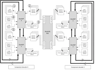
The UDec turbo decoder architecture [4] shown in Fig. 2 implements the turbo decoding system previously described. It consists of two rows of DecASIPs interconnected via a butterfly Network on Chip [7]. Each row corresponds to a component decoder. In the example in Fig. 2, four ASIPs are organized in 2 component decoders respectively built with 2 ASIPs. Within each component decoder the ASIPs are connected by two 80-bit buses for state metric exchange. The DecASIP implements the Max-Log MAP algorithm as described in [8]. It supports convolutional turbo codes up to eight-state double binary codes or sixteen-state single binary codes. Large frames are processed by dividing the frame
40 40
40 40
Component decoder 0 Component decoder 1
Butterfly NoC N o C in te rfa ce N o C in te rfa ce NoCin te rf a ce N o C in te rf a ce DecASIP 0 DecASIP 2 Extrinsic Memory (30x256) Program Memory (16x64) Config Memory (26x12) Input Memory (24x256)
Cross metric Memory (40x32) DecASIP 1 Extrinsic Memory (30x256) Program Memory (16x64) Config Memory (26x12) Input Memory (24x256)
Cross metric Memory (40x32) Extrinsic Memory (30x256) Program Memory (16x64) Config Memory (26x12) Input Memory (24x256)
Cross metric Memory (40x32) DecASIP 3 Extrinsic Memory (30x256) Program Memory (16x64) Config Memory (26x12) Input Memory (24x256)
Cross metric Memory (40x32)
1 2
3 5
4
Figure 2. UDec system architecture example with 2x2 ASIPs
into N windows each with a maximum size of 64 symbols. Each ASIP can manage a maximum of 12 windows. The DecASIP is associated with 3 memory banks of size 24x256 used to store the
input channel LLR values¬. There are also another 3 banks of
size 30x256 used for extrinsic information storing. Each ASIP is
further equipped with two 40x32 memories which hold state values ®. Moreover, Each ASIP is configured through a program ¯ and
a configuration memory °. The configuration memory contains
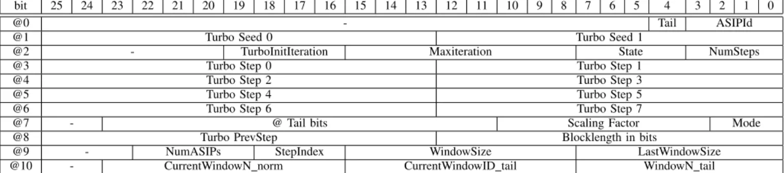
all parameters required to perform the initialization of the ASIP while the program memory contains the instructions in order to perform the decoding algorithm. Since the DecASIP is designed to work in a multi-ASIP architecture as described in [4], it requires several parameters to deal with a subblock of the data frame and several parameters to configure the ASIP mode. Concerning the subblock partitioning, each ASIP is configured with the size and the number of windows it has to decode. Furthermore, the last window size can be different so it corresponds to an additional parameter. In a single binary turbo code mode, the address of the tail bits in memory, the size and the number of windows for the tail bits have to be configured. Parameters for the ASIP mode correspond to the location of the ASIP in the architecture, the number of ASIPs required, the parameter which defines if the current ASIP is in charge of tail bits or not, the target standard (3GPP-LTE, WIMAX, or DVB-RCS) and the scaling factor for extrinsic information. Finally, some seed values are necessary for address generation in order to exchange information over the NoC that connects the ASIPs of each decoder component.
In order to address the dynamic configuration of the UDec Platform through the DecASIP configuration the architecture pre-sented in Fig. 3 is considered. It includes 4 DecASIPs that are configured thanks to a bus-based configuration infrastructure (the details of this infrastructure is out of the scope of this paper). Moreover, A Random generator associated with an Emitter produce the encoded symbols. The considered channel model is an Additive White Gaussian Noise (AWGN). The Input interface distributes the received symbols in the Input memories of each DecASIP. The configuration manager is in charge of the configuration generation. The configuration information is sent through the Master Interface to the Slaves interfaces that finally fill the configuration memory of each DecASIP. This configuration infrastructure provides an efficient solution to update DecASIP configuration memories using unicast, multicast or broadcast transfers. In [4], authors show that the DecASIP architecture provides high performance and high flexibility. However the topic of dynamic reconfiguration is not addressed. Despite its high flexibility, it presents some lacks to offer an efficient dynamic reconfiguration. The next section points out theses lacks and proposes several solutions to implement an efficient reconfigurable DecASIP for the UDec turbo decoder architecture.
III. PROPOSED OPTIMIZATIONS
Several optimizations are proposed to reach an efficient dynamic reconfiguration of the DecASIP architecture. The first optimization is related to the storage of configuration parameters. Currently, some parameters are stored in the configuration memory and others are provided in the program instructions directly [4]. The second optimization deals with the way used to load the configuration memory through the configuration memory organization. The third
bit 25 24 23 22 21 20 19 18 17 16 15 14 13 12 11 10 9 8 7 6 5 4 3 2 1 0
@0 - Tail ASIPId
@1 Turbo Seed 0 Turbo Seed 1
@2 - TurboInitIteration Maxiteration State NumSteps
@3 Turbo Step 0 Turbo Step 1
@4 Turbo Step 2 Turbo Step 3
@5 Turbo Step 4 Turbo Step 5
@6 Turbo Step 6 Turbo Step 7
@7 - @ Tail bits Scaling Factor Mode
@8 Turbo PrevStep Blocklength in bits
@9 - NumASIPs StepIndex WindowSize LastWindowSize
@10 - CurrentWindowN norm CurrentWindowID tail WindowN tail
Table I NEW CONFIGURATION MEMORY Butterfly NoC No C in te rfa ce No C in te rfa ce N oC in te rfa ce N oC in te rfa ce DecASIP 0 DecASIP 2 Extrinsic Memory (30x256) Program Memory (16x64) Config Memory (26x12) Input Memory (24x256)
Cross metric Memory (40x32) DecASIP 1 Extrinsic Memory (30x256) Program Memory (16x64) Config Memory (26x12) Input Memory (24x256)
Cross metric Memory (40x32) Extrinsic Memory (30x256) Program Memory (16x64) Config Memory (26x12) Input Memory (24x256)
Cross metric Memory (40x32) DecASIP 3 Extrinsic Memory (30x256) Program Memory (16x64) Config Memory (26x12) Input Memory (24x256)
Cross metric Memory (40x32) Input interface Channel Noisy symbols Emitter Symbols Random generator Platform controller Verification module To ASIPs To NoC Hard decision from ASIPs Config Memory (26x12)
Control flow Data flow Configuration flow
Mem.@ Data T_enable Dest. @ Selector Slave Interface 0 (SI_1) Slave Interface 1 (SI_3) Slave Interface N (SI_4) Slave Interface 0 (SI_0) Slave Interface 0 (SI_2) Master Interface (MI) T_init D_enable Data Base. @ Dest. @ Configuration Manager 26 8 8 26 8 8 T E S T B E N C H U D E C A R C H I T E C T U R E C O N F I G U R A T I O N I N F R A S T R U C T U R E
Figure 3. Architecture of the proposed configuration infrastructure for the
UDec platform.
optimization corresponds to the development of a generic program independent of the configuration to be performed.
A. Configuration parameters storage
To reach (re)configuration efficiency, we propose to move all parameters from the program memory to the configuration memory. This solution allows to (re)configure a single memory to change all the configuration parameters (instead of loading both new program memory and configuration memory). Furthermore, once the ASIP is configured, the configuration memory can be accessed without any conflict since the configuration is loaded inside internal registers of the ASIP during the initialization step. This is a key point to prepare the next configuration if necessary. Indeed, the entire next
configuration can be loaded in the configuration memory during the processing of the current data frame. Thus the configuration loading can be partially or completely masked. If the configuration loading is completely masked, the configuration overhead consists in the initialization step only. However, this modification impacts the area of the configuration memory since it is necessary to store more parameters. It also impacts the number of registers inside the ASIP in order to store these parameters after the initialization step. Finally, it impacts the initialization step duration since this step consists in reading the configuration memory and then storing each parameter in the corresponding register. The program in its current form contains eight configuration parameters. So eight parameters have to be added to the configuration memory to obtain a parameter independent program memory. The next sub-section presents a way to integrate these new parameters in a smart memory organization. B. Configuration memory organization
In order to improve the (re)configuration of the ASIP, it is essential to analyze the organization of the configuration memory. The parameters stored in the configuration memory are very spe-cific. They can be divided in four categories: 1) domain dependent (for component decoder 0 or component decoder 1 in Fig. 1), 2) identical for all ASIPs, 3) different for all ASIPs and 4) different for the last ASIPs which decode the tail bits in a single binary turbo code mode. All these characteristics need to be taken into account in order to build a low latency configuration process. Furthermore, in a multi-ASIP context, it is necessary to only configure ASIPs required for a specific execution context (it means that only a subset of ASIPs may be required depending on the performance to be achieved). A smart memory organization should allow an efficient broadcasting of the configuration parameters to the required ASIPs. thus we propose to group the parameters depending on the previously described categories. Four groups which occupy four different parts of the configuration memory are defined.
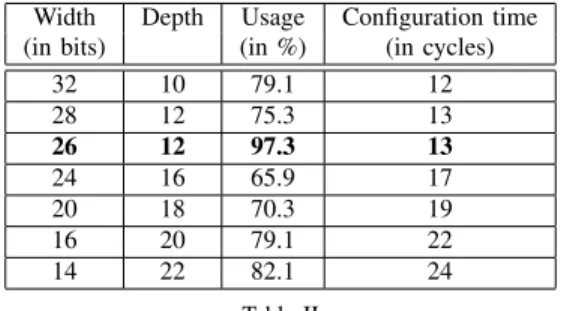
As different memory architectures can be considered, it is important to define the best size for the memory. Table II shows that the choice of the width and depth of the memory impacts the time required to load the configuration into the ASIP and the area of the memory on the chip. We evaluate five solutions from 14 bits to 32 bits memory width. Since the number and the size of each parameter are fixed, the depth of the memory decreases when the width increases. Furthermore, in order to take into account the final
Width Depth Usage Configuration time
(in bits) (in %) (in cycles)
32 10 79.1 12 28 12 75.3 13 26 12 97.3 13 24 16 65.9 17 20 18 70.3 19 16 20 79.1 22 14 22 82.1 24 Table II
CONFIGURATION MEMORY ARCHITECTURE ALTERNATIVES
implementation of the different memory alternatives, the depth and width of each memory must be a multiple of 2. It represents the minimal constraint to design the memory (this constraint is related to the memory technology considered for our design). Depending on the alternative, the level of memory usage changes. Results of Table II show that a 26 bits memory width is the most efficient one (97.3%) while a 24 bits memory width is inefficient (65.9%). The time required to configure the ASIP is proportional to the number of memory lines to be read. Each clock cycle, the ASIP reads one data from the memory and configures the corresponding register. One more clock cycle is necessary to initialize the reading loop, and another cycle is required to complete the initialization of the ASIP. For example, 12 cycles are needed to load the configuration in the ASIP with a 32 bits memory width while 24 cycles are necessary for a 14 bits memory width. Moreover, the memory width has an impact on the global multi-ASIP platform. Indeed, a large memory width increases the number of connections between each ASIP and its configuration memory and between each configuration memory and the link that is used to load the configuration parameters in the memories (Fig. 3). Thus, a trade-off between the initialization time, the memory usage and the global impact on the platform has to be found. The 26 bits memory width is an interesting trade-off. This memory alternative offers a fast configuration time (13 cycles) and the highest memory usage efficiency (97.3%). Finally, the impact on the entire platform is low compared to the current solution that implements a 24 bits memory width. This point will be further discussed in the result section.
Table I shows the 26 bits width configuration memory organi-zation. The memory is organized as follows: (1) from address @0 to @1, parameters can be different for each ASIP. Furthermore, to optimize the initialization step of the ASIP, the parameter Tail which indicates if the ASIP has to perform or not the tail bits is included in this group. Only the last two ASIPs are concerned by the tail bits in a single binary turbo code mode; (2) from address @2 to @6, the parameters are domain dependent; (3) from address @7 to @10, the parameters are the same for all ASIPs. This organization allows a good way for a fast reconfiguration at the platform level. Indeed, multicast mechanisms can be used to load the configuration in order to minimize the data transfers load. In this context, two multicast transfers are necessary to send domain dependent parameters to all ASIPs and one multicast transfer for parameters that are the same for all ASIPs. Finally, unicast transfers are used to load the ASIP dependent parameters.
C. Generic program
We propose to simplify the (re)configuration mechanism by using a unique generic program stored in a ROM memory. Since all parameters contained in the program memory have been moved to the configuration memory, three possibilities exist for the program: two programs for single binary turbo code and one program for duo binary turbo codes. In single binary mode, after the initialization step, the last two ASIPs have to perform the tail bits while other ASIPs execute NOP operations. So, a particular program is loaded in these last two ASIPs. In duo binary mode, data frames are decoded after the initialization step. In order to merge these three possible programs, the new unique program has to be able to tackle these three cases. For this purpose, the program which integrates the tail bits computation is used as a reference. We have chosen to modify the Fetch pipe stage of the ASIP in order to detect and replace the instructions for tail bits with NOP instructions if the ASIP is not concerned. The value of the bit Tail stored in the configuration memory (Table I) determines if the ASIP is concerned or not by tail bits decoding. In duo binary mode, no tail bits have to be decoded. So, using a unique program in this mode adds 12 extra
NOPinstructions before the decoding step which corresponds to
tail bits computation in single binary mode. However, these extra clock cycles are negligible regarding the number of cycles required to perform the decoding on one entire data frame (for example, around 3000 cycles are necessary to execute the entire program on a 960 bits data frame in single binary mode with 8 ASIPs applying 6 iterations).
Optimizations described in this section allow to reduce the (re)configuration impact: 1) locally through the optimization of the storage of configuration parameters to efficiently use the memory capacity and 2) globally thanks to the new memory organization and the generic program which reduce the total configuration load to be transferred through the configuration infrastructure (Fig. 3) when a new configuration has to be performed. The next section presents the implementation and the impact of proposed optimizations in the DecASIP.
IV. IMPLEMENTATION AND RESULTS
A. ASIP implementation
Optimizations described in Section III have been implemented on the DecASIP presented in [4]. To provide more flexibility for future configuration organization, input pins have been added to inform the ASIP about the size of the configuration. The ASIP was modeled in LISA language using Synopsys (ex. Coware) Pro-cessor Designer tool. Synthesis of the previous and the new cores was done with 65nm CMOS technology with a clock frequency objective equals to 500MHz. Synthesis results have been extracted to determine the impact of the optimizations on the pipeline and the register file of the ASIP.
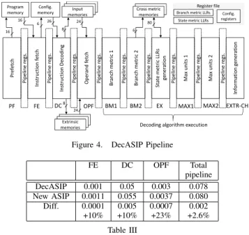
To evaluate the impact of the new features on the ASIP area, we extracted the area synthesis results for each pipeline stage of the ASIP. This ASIP consists of 10 pipeline stages as shown in Fig. 4. The reconfiguration optimizations presented in this paper do not affect all the stages. Only three stages are impacted. Indeed, from BM1 to EXTR-CH, stages are dedicated to data computation and this part of the ASIP pipeline is not directly concerned by
26 P re fe tc h P ip e li n e r e g s. In st ru ct io n f e tc h P ip e li n e r e g s. O p e ra n d f e tc h P ip e li n e r e g s. B ra n ch m e tr ic 1 P ip e li n e r e g s. B ra n ch m e tr ic 2 P ip e li n e r e g s. S ta te m e tr ic L LR s g e n e ra ti o n P ip e li n e r e g s. M a x u n it s 1 P ip e li n e r e g s. M a x u n it s 2 P ip e li n e r e g s. In fo rm a ti o n g e n e ra ti o n
PF FE OPF BM1 BM2 EX MAX1 MAX2 EXTR-CH
Program memory P ip e li n e r e g s. In st ru ct io n D e co d in g DC Input memories Cross metric memories Config. memory Extrinsic
memories Decoding algorithm execution
16 16 6 8 24 8 24 6 80 Register file Branch metric LLRs State metric LLRs Config. registers
Figure 4. DecASIP Pipeline
FE DC OPF Total pipeline DecASIP 0.001 0.05 0.003 0.078 New ASIP 0.0011 0.055 0.0037 0.080 Diff. 0.0001 0.005 0.0007 0.002 +10% +10% +23% +2.6% Table III
PIPELINE STAGES AREA COMPARISON INmm2
the configuration optimizations proposed in this work. Moreover, The pre-fetch stage is identical in the two implementation of the DecASIP. On the other hand, fetch (FE), decode (DC), and operand fetch (OPF) stages have seen their area increased compared to the previous ASIP. Table III presents area synthesis results for each impacted pipeline stage for the original ASIP and the new version. The proposed optimizations were implemented along the pipelines stages as follows:
• FE: The FE stage insures the automatic replacement of
in-structions for tail bits computation by NOP when the ASIP is not concerned by tail bits decoding.
• DC: This stage is mainly impacted by the transfer of all
flex-ible parameters in a unique configuration memory. Instead of a direct access to some parameters in instruction code words, parameters are now read from registers. Thus, the number of connections with the register file has been increased.
• OPF: This stage is impacted by the new configuration memory
organization since it is in charge of the parameter registers initialization. The area overhead comes from the increasing number of parameters in the configuration memory and by added control structures that manage the configuration size flexibility. Since more configuration parameters are read from the configuration memory, the number of connections with the register file has been increased to configure additional registers.
Regarding results from Table III for the complete pipeline of the ASIP, we observe that despite of the different area overheads on the first pipeline stages caused by our optimizations, the global area
overhead for the complete pipeline is 2.6% (0.002 mm2). Indeed,
the most complex part of the pipeline consists of the execution stages that implement the decoding algorithm.
On the register file side, this increasing is around 14.5% (0.011
mm2).
Table IV shows the global area comparison between the
De-Pipeline Register Total
file ASIP DecASIP 0.078 0.076 0.175 New ASIP 0.080 0.087 0.179 Diff. 0.002 0.011 0.004 +2.6% + 14.5% +2.3% Table IV
ASIPAREA COMPARISON INmm2
cASIP and the new version optimized for dynamic reconfiguration. We observe that the global logic overhead on the ASIP is 2.3%
(0.004 mm2). This overhead is mainly due to the register file.
So, the increasing complexity of the ASIP is mainly due to the additional internal registers used to store the configuration parameters read from the configuration memory.
B. Dynamic reconfiguration performance
In this section, we evaluate the gain of proposed optimizations on reconfiguration timing performance. For this purpose, we consider the following reconfiguration steps:
1) Memories loading: The first step of the configuration pro-cess is the transfer of the configuration parameters in the configuration memory of one or several ASIPs.
2) ASIP Initialization: When the configuration parameters are available in the memory, the ASIP can start the initialization process. During this step, the ASIP reads the configuration stored in the configuration memory and initializes the internal registers. Then, the ASIP is ready to execute the computation on the input data frame.
Table V compares the configuration and program load (in bits) for the proposed ASIP, the original DecASIP presented in [4] and the ASIP presented in [5]. For one ASIP, we observe that the proposed ASIP can be configured with 286 bits instead of 976 bits thanks to the generic program described in Section III-C while 1463 bits and the complete interleaver table are required for the ASIP in [5]. Moreover, the new memory organization proposed in Section III-B allows the optimization of the configuration memory loading. Indeed, parameters are sent to several ASIPs through multicast mechanism presented in Section II. Thus, in a multi-ASIP context, each original ASIP has to be configured with its own configuration and program memory while configuration memory of the proposed new ASIP can be loaded using a multicast mechanism as follows: 52 bits are independently loaded in each ASIP. ASIPs that compose the same decoder component (Fig. 1) are loaded with 130 common bits. Finally, 104 configuration bits are broadcasted to all ASIPs. Thanks to this new configuration memory organization, the impact of the number of ASIPs on the configuration load is significantly reduced: n.52 bits instead of n.976 bits, where n is the number of ASIPs implemented. For example, if 8 ASIPs are implemented in a multi-ASIP platform, the configuration load to configure the 8 ASIPs is 7808 bits with the original DecASIP, 11704 bits for [5] plus the interleaver tables and 780 bits with the proposed ASIP. In this case the configuration load is divided by 10 and 15 compared to the DecASIP and the ASIP from [5] respectively. Finally, it is interesting to note that the configuration infrastructure presented in Section II providing multicast mechanism has a low area overhead
Config Prog. 1 n
param. mem. ASIP ASIPs
New ASIP 286 - 286 n.52+260+104
DecASIP 336 640 976 n.976
Gain 14% 100% 70% 90% (n = 8)
[5] 383 + ∼1080 1463 + n.1463
Interl. Inter. n.Interl.
Gain 25% 100% 80% 93% (n = 8)
Table V
CONFIGURATION AND PROGRAM BIT LOAD COMPARISON IN BITS
that are implemented in the considered UDec platform. Moreover, the configuration of the 4 DecASIPs are performed in 2µs.
The new configuration memory area is reduced by 7.5% (i.e.
194 µm2) compared to the original implementation. Its new
orga-nization has also an impact on the initialization time of the ASIP. Indeed, for each new configuration, the ASIP reads the parameters from the configuration memory and initializes the internal registers. The new memory organization reduces the number of read accesses to the memory. Only 11 read accesses are necessary instead of 15 in the original ASIP. Thus the initialization time is reduced by 4 cycles. Thus, the ASIP can be reconfigured in 12 clock cycles if we assume that one extra clock cycle is necessary to drive the reset pin of the ASIP. Furthermore, when the initialization step is performed, the ASIP does not read the configuration memory until the next initialization. Hence, during the computation on a data frame, configuration parameters can be loaded in the configuration memory. The memory loading process can be partially or totally masked depending on when the reconfiguration order is triggered. If the loading process is masked, the complete (re)configuration of a multi-ASIP platform represents an overhead of around 12 clock cycles. This low (re)configuration time overhead allows the imple-mentation of such an optimized ASIP in multi-ASIP architecture for future high throughput and low latency requirements.
The timing performances for turbo decoding of the new and the original version of the DecASIP are purely identical. Indeed, the pipeline architecture is still the same and both implementation are able to reach the maximum frequency of 500MHz. However, in double binary mode, the new version of DecASIP requires 12 extra clock cycles after the initialization phase to start decoding. Since the initialization phase for the new version is 4 clock cycles shorter than for the original version, the new DecASIP requires 8 extra clock cycles before the beginning of the decoding in double binary mode while it is able to start the treatments 4 clock cycles before the original DecASIP in simple binary mode. Nevertheless, we can disregard these impacts in front of the decoding time of a data frame that is identical for both version of the DecASIP.
V. CONCLUSION
Multi-ASIP architectures for turbo decoding is a promising approach to reach high flexibility and high throughput requirements imposed by new emerging communication standards. Due to the increasing throughput and the reduction of latency between two data frames, the configuration of such multi-core platforms is becoming a critical point. In this paper, we propose to optimize a standard ASIP for an efficient (re)configuration in a multi-ASIP context. Results show that configuration load of the multi-ASIP
has been reduce by 70% compared to the original implementation. Furthermore, in a multi-ASIP context implementing 8 ASIPs, the proposed smart configuration memory organization allows dividing the configuration load by 10 using a multicast mechanism. Future work targets the evaluation of the power consumption in order to analyze the impact of our optimizations with respect to power and energy that are main issues.
REFERENCES
[1] C. Berrou, A. Glavieux, and P. Thitimajshima, “Near shannon limit error-correcting coding and decoding: Turbo-codes. 1,” in Commu-nications, 1993. ICC 93. Geneva. Technical Program, Conference Record, IEEE International Conference on, vol. 2, may 1993, pp. 1064 –1070 vol.2.
[2] C. Brehm, T. Ilnseher, and N. Wehn, “A scalable multi-ASIP ar-chitecture for standard compliant trellis decoding,” in International SoC Design Conference (ISOCC), 2011, pp. 349 –352.
[3] T. Vogt, C. Neeb, and N. Wehn, “A reconfigurable multi-processor platform for convolutional and turbo decoding,” in Proc. of In-ternational Workshop on Reconfigurable Communication-centric Systems-on-Chip (ReCoSoC), 2006, pp. 16–23.
[4] P. Murugappa, A.-K. R., A. Baghdadi, and M. J´ez´equel, “A Flexible High Throughput Multi-ASIP Architecture for LDPC and Turbo Decoding,” in Proc. of Design, Automation and Test in Europe Conference & Exhibition (DATE), 2011.
[5] T. Vogt and N. Wehn, “A reconfigurable asip for convolutional and turbo decoding in an sdr environment,” Very Large Scale Integration (VLSI) Systems, IEEE Transactions on, vol. 16, no. 10, pp. 1309 –1320, oct. 2008.
[6] “Ieee standard for local and metropolitan area networks part 16: Air interface for fixed and mobile broadband wireless,” IEEE Std 802.16e-2005, 2006.
[7] H. Moussa, A. Baghdadi, and M. Jezequel, “Binary de bruijn on-chip network for a flexible multiprocessor ldpc decoder,” in Design Automation Conference, 2008. DAC 2008. 45th ACM/IEEE, june 2008, pp. 429 –434.
[8] P. Robertson, P. Hoeher, and E. Villebrun, “Optimal and sub-optimal maximum a posteriori algorithms suitable for turbo decoding,” European Transactions on Telecommunications,
vol. 8, no. 2, pp. 119–125, 1997. [Online]. Available: