HAL Id: hal-01175000
https://hal.archives-ouvertes.fr/hal-01175000
Submitted on 10 Jul 2015
HAL is a multi-disciplinary open access
archive for the deposit and dissemination of
sci-entific research documents, whether they are
pub-lished or not. The documents may come from
teaching and research institutions in France or
abroad, or from public or private research centers.
L’archive ouverte pluridisciplinaire HAL, est
destinée au dépôt et à la diffusion de documents
scientifiques de niveau recherche, publiés ou non,
émanant des établissements d’enseignement et de
recherche français ou étrangers, des laboratoires
publics ou privés.
Plasticity for 3D User Interfaces: new Models for
Devices and Interaction Techniques
Jérémy Lacoche, Thierry Duval, Bruno Arnaldi, Éric Maisel, Jérôme Royan
To cite this version:
Jérémy Lacoche, Thierry Duval, Bruno Arnaldi, Éric Maisel, Jérôme Royan. Plasticity for 3D User
Interfaces: new Models for Devices and Interaction Techniques. Proceedings of EICS 2015 : 7th ACM
SIGCHI Symposium on Engineering Interactive Computing Systems, Jun 2015, Duisburg, Germany.
pp.28 - 33, �10.1145/2774225.2775073�. �hal-01175000�
DRAFT
Plasticity for 3D User Interfaces:
new Models for Devices and Interaction Techniques
J´er´emy Lacoche
IRT b
<>com, UMR CNRS
6074 Irisa - Inria Rennes
[email protected]
Thierry Duval
UMR CNRS 6285
Lab-STICC, Telecom
Bretagne, IRT b
<>com
[email protected]
Bruno Arnaldi
UMR CNRS 6074 Irisa - Inria
Rennes, INSA de Rennes, IRT
b
<>com
[email protected]
Eric Maisel
UMR CNRS 6285
Lab-STICC, ENIB, IRT
b
<>com
[email protected]
J´erome Royan
IRT b
<>com
[email protected]
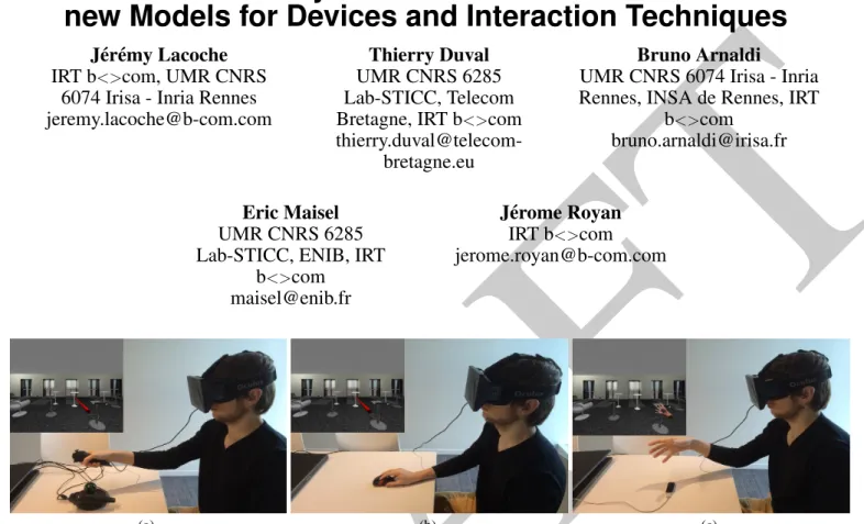
(a) (b) (c)Figure 1: Different ways to complete a Selection and Manipulation task with the proposed interaction model (a) A 3D-ray based interaction controlled by a razer hydra is used (b) Without this device connected, the ray is now controlled with the mouse (c) With the leap motion, another interaction technique is chosen, a 3D-cursor controlled with the user’s hand.
ABSTRACT
This paper introduces a new device model and a new interac-tion technique model to deal with plasticity issues for Virtual Reality (VR) and Augmented Reality (AR). We aim to pro-vide developers with solutions to use and create interaction techniques that will fit to the needed tasks of a 3D applica-tion and to the input and output devices available. The de-vice model introduces a new description of inputs and outputs devices that includes capabilities, limitations and representa-tions in the real world. We also propose a new way to de-velop interaction techniques with an approach based on PAC and ARCH models. These techniques are implemented inde-pendently of the concrete devices used thanks to the proposed device model. Moreover, our approach aims to facilitate the
Permission to make digital or hard copies of all or part of this work for personal or classroom use is granted without fee provided that copies are not made or distributed for profit or commercial advantage and that copies bear this notice and the full cita-tion on the first page. Copyrights for components of this work owned by others than ACM must be honored. Abstracting with credit is permitted. To copy otherwise, or re-publish, to post on servers or to redistribute to lists, requires prior specific permission and/or a fee. Request permissions from [email protected].
EICS’15, June 23 - 26, 2015, Duisburg, Germany c
2015 ACM. ISBN 978-1-4503-3646-8/15/06...$15.00
portability of interaction techniques over different target OS and 3D framework.
Author Keywords
3D User Interfaces; Virtual Reality
ACM Classification Keywords
H.5.1 Information interfaces and presentation: Multimedia Information SystemsArtificial, augmented, and virtual realities; H.5.2 Information interfaces and presentation (e.g. HCI): User Interfaces
INTRODUCTION
In the last years, interest in 3D user interfaces has grown [2]. For instance, 3D user interfaces include Virtual Environments (VE), serious games or Computer-Aided Design (CAD) ap-plications. They differ from traditional graphical user inter-faces (GUI) by including a third dimension to present content and by using a wider range of interaction devices than the traditional set: mouse, keyboard and touch-screen.
With the wide variety of existing interaction devices and the daily emergence of new ones, it is difficult and time consum-ing for developers to adapt their applications to each possible
DRAFT
configuration. For instance, in these new devices we can find the Microsoft R KinectTM, the Leap Motion or the Oculus rift.
More than using each time a new SDK, these devices lead de-velopers to redevelop parts of their applications, particularly interaction techniques in order to fit each capability.
Developing an application that takes into account the plastic-ity property is one solution to deal with these issues. Plas-ticity is the capacity of an interactive system to withstand variations of both the system physical characteristics and the environment while preserving its usability [17]. Code inter-operability and usability continuity has to be guaranteed to be considered as plastic. Plasticity has already been well ex-plored in the field of 2D user interfaces, however it has been reported in [12] that the problem is even larger for 3D and that no solution meets all the plasticity requirements. Our goal is to propose new solutions for developers to han-dle plasticity for 3D user interfaces. In this paper, we focus on interaction techniques. In [3], an interaction technique is defined as a method allowing a user to accomplish a task via the user interface. It includes both hardware (input/output) and software components. We want to be able to define inter-action techniques that will work whatever the target context of use. This context consists in a description of the available devices through a new device model and a high level descrip-tion of the tasks that have to be performed. This device model aims to describe devices in terms of data they can collect and provide. It differs from classic approaches by also including information such as intrinsic properties, limitations and rep-resentation in the real world. Then, the interaction technique model based on PAC and ARCH models gives the possibility to developers to implement interaction techniques indepen-dently of devices and of a target 3D framework.
This paper is structured as follows: first we recall the plastic-ity requirements for 3D that our models have to meet. Then, we introduce our new device model used in the context de-scription. Next, we present an extension of the PAC model [7] for interaction techniques implementation that ensures in-dependence from the devices and from the target VR frame-work. Last, we conclude and give directions for future frame-work.
REQUIREMENTS
To handle the plasticity property for interaction techniques, our models have to take into account a set of 3D requirements such as some reported by Lacoche et al. in [12]:
R1 Ensure code portability. Interaction techniques must be available on many Operating Systems (mobile and desk-top). Moreover they need to be possibly integrated or im-plemented with the main 3D frameworks (for instance, a game engine) and not dependent on a particular one. In-deed, each developer may have his own code database or 3D content in a particular framework.
R2 Independence over the devices used. Interaction tech-niques must work whatever the concrete devices available. The devices needed by an interaction technique must be defined with a high level description. Alternatives must be possibly defined in case of a compatible device is not
found. Moreover, interaction techniques must be aware of the device properties.
R3 Handle user and system adaptations. Interaction tech-niques must be possibly instantiated with an automatic adaptation process, this is adaptivity. However, the user has to be able to modify the interaction techniques with a set of predefined parameters, this is adaptability.
R4 Interaction techniques must be configurable at runtime (dy-namic adaptation) and between sessions (static adapta-tion). To ensure usability continuity, context modifications, such as a device plugged or a new task needed, must be recorded. The interaction techniques have to be dynami-cally adapted according to the context modifications.
A NEW DESCRIPTION FOR INPUTS AND OUTPUTS
In order to perform hardware adaptations and fullfill the sec-ond requirement (R2), an accurate description of the input and output devices is needed: this is the device model. In-deed, the adaptation process has to know which devices are available, their capabilities and limitations. This model is needed to perform device selection and adaptation. In the model, inputs devices are considered as the devices that can collect data from the real world. For example, a position, a pressure on a button or a sound acquisition. Regarding output devices, they restitute computer generated values to the real world, for instance an image on a screen or a vibration. In the literature we can find several classifications about how to perform static or automatic input device selection, such as the Buxton taxonomy [4] extended later by Mackinlay et al. [15] and also DEVAL [16] a device abstraction layer for VR and AR applications. They consider a device as a composi-tion of several input units where each unit is responsible to acquire one kind of data. This kind of classification aims to describe the data provided by input devices units such as the number of degrees of freedom (DoF) of an input value or the property sensed (position, motion, pressure). DEVAL has the advantage to describe a wide variety of device units. It in-cludes more recent devices that can also have output capabil-ities. For instance, trackers, buttons, haptic feedback, speech and gesture recognition. Less common sensors are also in-cluded such as light and temperature sensors. This classifica-tion hierarchically structures inputs and outputs units accord-ing to their properties. Anyway, this model and the previous ones only define devices with input and output data while it would be interesting to also expose their physical properties in the real physical workspace or their internal properties like refresh rate or accuracy. The graph representation of devices proposed by Lipscomp and Pique [14] and the DEVAL exten-sion introduced by Lindt [13] expose this kind of meta-data. Lipscomp and Pique [14] give the physical characteristics of each device and so a more precise description on how the data is acquired and their limitations. For example, it differentiates bound and unbound inputs as well as isotonic, isometric and elastic ones. In the DEVAL extension [13], three kinds of meta-data can be added to a device unit. First, static devices properties do not change over the time such as the weight of a HMD. Next, configurable devices properties depend on the device setup like the smoothing factor of a tracking
de-DRAFT
Figure 2: A device is a set of inputs and outputs as well as a collection of physical objects for its real representation. vice. Finally, runtime properties include performances and device states. The classification into three categories can be discussed because the associated category of a property may change over different devices. For instance, the resolution of an image acquired by a camera can be configurable for some devices such as the Microsoft R KinectTM while for most of
them it is a static value. Moreover, the set of properties intro-duced in the model does not include enough properties to pre-cisely describe the capabilities of each device. For instance, values boundaries and devices position are not included. Our device model aims to solve these issues with an accu-rate description of the devices capabilities, limitations and of their representation in the real world. The model must be ex-tendable because new devices will still appear and they might include new properties not yet included in the current model. The model is described with UML class diagrams, so it is totally editable by any developer who wants to add new prop-erties or a new input or output type. At runtime the propprop-erties of a device instance are fulfilled with an XML description file edited with a graphical tool that takes into account the UML diagram. Then, the developer has to complete some functions to fulfill the input data, trigger the outputs when needed and update the dynamic parameters. Moreover, a function has to be implemented in order to tell the system when a new in-stance of the device is plugged or unplugged. These steps can be done with a device SDK. Static properties have to be fulfilled into the description before execution if needed, for instance the position of a device in the real world. These properties can also be reported into the device SDK to per-form its configuration.
In the model, we consider an interaction device as a complex entity that may acquire input(s) and render output(s) and that has a representation in the real world. As shown in Figure 2, the model represents a device as a collection of inputs, out-puts and physical objects entities. A device is defined by its name, the name of the SDK used to manage it, its index in the case we use different instances of the device, and a boolean that indicates if it is plugged or not.
The set of physical objects describes the representation of the device in the real world. For example, it gives properties such as a 3D representation of the device if we want to represent it in the virtual world. Its position gives the possibility to a developer to automatically adapt the coordinate system of the tracking values. Moreover, all inputs and outputs are associ-ated to a physical object, this information may help to select an input or an output unit used by an interaction technique. Indeed, for an interaction technique, inputs and outputs that correspond to the same physical object can be preferentially
Figure 3: The description of real value input with two entities: the ”data description” and the ”technology”.
selected. The goal would be to minimize device switchings as well as the homing time of the GOMS model [6].
Regarding input description, the goal is to describe all pos-sible acquired signals that are currently used in 3D applica-tions. We established a list of three categories that gather these possible inputs:
• real values: the most common value type used. It refers to continuous values acquired by trackers, sensors, touch-screens, etc. It can represent a position or a rotation as well as more original values such as a temperature or the lighting intensity of a room.
• discrete values: taken into a set of predefined ones. For example a button pressed or not, a gesture or a vocal com-mand.
• Generic streams: they continuously provide array of val-ues. This category is divided into multiple subtypes with more specific properties (image streams, EEG signals, sound acquisition...)
In the model, these different input types include a description of the acquired data, their properties and limitations, and in-formation about how these data are acquired by the device. To do so, we propose to describe each input into two entities. The ”data description” ensures the first need, and the ”tech-nology” ensures the second one.
For the two entities of the real value input type described in figure 3, the description reuses the most important properties of previously described taxonomies, especially [14] and [15], while adding some new ones. Regarding the new properties, three booleans describe the axis on which the value is defined as proposed by Mackinlay et al [15]. A fourth axis called ”none” is also included for values that are not expressed in a 3D coordinate system, for example a temperature. To con-tinue, the semantics lets the developer know which real world data is acquired. For example, it can be the name of a body joint in the case of the Microsoft R KinectTM. In the
”tech-nology” entity, we included a reliability rank of the acquired data between 0 and 1, this property is present for all input types. This value may change at runtime, as some SDK are able to give a reliability score for each value acquired. With the ”Techno Real Type” property, we differentiated the values acquired with a distant wireless sensor and with a physical object. For example with optical tracking there is no interme-diary for the interaction contrary to a gamepad.
DRAFT
Figure 4: The description of a force feedback output.
A description of output devices is also included. An output is described by one entity that provides the information about how the data is rendered to the real world. All output types but visual and sound are extracted from the MPEG-V stan-dard [10]. These types are:
• Visual outputs. They include screens such as monitors and HMDs. They also encompass punctual lights, for instance a gamepad led or a remotely controlled lighting system that modifies the lighting conditions of the real world.
• Sound outputs. They stimulate the auditory sense and in-clude devices such as speakers and headphones.
• Tactile outputs. They stimulate the touch sense, for exam-ple the vibration of a gamepad.
• Force-feedback outputs. They apply a force in return of a user interaction in order to simulate a collision with a virtual object. Typical force devices are robotics arms. • Temperature outputs. They modify the temperature of the
real world or of a contact point. An example is to control the temperature according to the weather conditions in a virtual world.
• Wind output. They change the air speed and direction dy-namically.
• Scent outputs. They stimulate the olfactory sense.
• Sprayer outputs. They can throw water on a user. It can be used to simulate a virtual rain effect in the real world. Three properties are common to all output and input types: the name, the refresh rate and a possible associated relative object. For instance, the force feedback type properties are listed in Figure 4. The first three properties are extracted from the description of force feedback devices given by Florens et al. [8]. First, the continuous force is the maximum force that can be applied for an unlimited period without damaging the device. Secondly, the peak force is the maximum feasible force. Thirdly, the force resolution gives the quantization step of the force that can be applied. All these values are expressed in newtons. Then, we have extended this description with a boolean for each DoF on which the device can apply a force. In this section we have introduced an extendable device model to perform device selection and adaptation. Two con-crete examples of descriptions of device units types have been given, real values for inputs and haptic rendering for outputs. The other listed inputs and outputs types are also described in the model. We need such a model to adapt the interaction techniques to the hardware configuration (R2). In order to fit R4 the model can be configured before a session and updated at runtime. In the next section, we show how this model is
used to perform automatic selection of device units and for device intrinsic parameters adaptations.
PAC AGENTS FOR INTERACTION TECHNIQUES
Having modeled input and output devices, we now focus on the interaction techniques that work independently from any concrete device thanks to this model. Interaction techniques are created in order to complete a high level task needed in the target application. For 3D user interfaces, according to Hand [11], these tasks belong to three categories: selection and ma-nipulation, application control and navigation. According to the plasticity requirements, there is a need for a model for in-teraction technique description that ensures a good portability over the possible target 3D frameworks and an independence of techniques over the interaction devices.
A convenient model could be PAC [7] (Presentation-Abstraction-Control), a multi-agent model that ensures a good decoupling between user interface semantics and its concrete implementation. It decomposes an interaction com-ponent into three facets:
• the Presentation: it is the concrete implementation of the component in charge of its input and output management, • the Abstraction: it describes the semantics of the
compo-nent and the function it can perform,
• the Control: it ensures the consistency between the presen-tation and the abstraction.
However, this model has not been designed to perform con-text adaptation: a PAC agent will be the same whatever the target platforms and users. Therefore, Calvary et al. intro-duced Compact [5] (COntext of user Mouldable PAC for plas-ticity) a specialization of PAC. Compact divides each facet into two parts, the physical part that is dependent from the current context and the logical one which is always the same. For instance, an algorithm used by the abstraction facet can be replaced according to the target platform performances by just replacing the physical part. However, keeping the se-mantics and algorithms constant whatever the context was the main interest of the PAC model with its presentation facet that deals with it. PAC does not provide a good decoupling between the input and the output management because the Presentation facet includes both. This decoupling is needed in 3D because of the larger set of possible devices. To solve this issue Grappl [9] describes an interaction technique with a base class that performs semantics and presentation compu-tation. This class is extended by other classes that implement different ways to control the technique with several sets of interaction devices. Compared to PAC, the method does not ensure a good decoupling between semantics and presenta-tion and a good independence to the target 3D framework. Indeed, Grappl uses its own internal scene graph system. To solve all of these issues we represent the interaction tech-nique model with a PAC model enhanced with ARCH con-cepts [1]. ARCH proposes to add adaptor components be-tween the different facets of PAC-like models. This model is also considered as a meta-model for other software mod-els by proposing a generic separation between facets of inter-active components. ARCH represents an interinter-active
compo-DRAFT
Driver Fly Navigation
«Joysticks »
Action: Orientation Control Action: Position Control
Action: Collision Feedback Optional
Type : Tactile Output Needed Type : Real Input Axe X : Yes Axe Y : Yes Axe Z : No Real Value Type : FORCE Bounds : [(-1 , -1 , 0 ,0) , (1 ,1 , 0 ,0)]
Needed Type : Real Input Axe X : Yes Axe Y : Yes Axe Z : No Real Value Type : FORCE Bounds : [(-1 , -1 , 0 ,0) , (1 ,1 , 0 ,0)]
Needs
Figure 5: An example of a logical driver and its device units needs. It controls a fly navigation interaction technique with joysticks. The first needs are two real values that describe the two joysticks needed. A need is defined with some properties extracted from the device model. As shown some properties can be omitted, only the detailed ones will be used to select the available device units. The last one is tactile feedback, which is optional and can give a vibration feedback when the user collides any 3D object.
nent as a set of facet branches dedicated to specific features such as presentation and data processing. Our model differs from PAC by separating the original presentation facet into two branches as shown in Figure 6. No adaptor component is currently used. The two branches are based on its rendering and device management core functions:
• The rendering facet is the only facet depending on a 3D framework. It handles graphics output and physics. • The logical driver handles input and output devices
man-agement. It describes the way the interaction technique is controlled according to a set of interaction device units. The work of the developer is to choose these device units in order to drive correctly the interaction technique. The logi-cal driver describes all required inputs and outputs units ac-cording to a set of parameters taken from our device model. Some can be optional if they are not needed for a good us-ability. The logical driver can be instantiated if these units can be found at runtime. At runtime, the logical driver receives the input data that it needs and it can trigger the outputs. The device units may come from different con-crete devices in order to perform device composition. An example of logical driver is given in Figure 5.
Getting the data independently from concrete devices is one of the possibilities given by the logical driver. Nevertheless, it does not ensure the same behavior over all the devices be-cause all do not have the same capabilities and the same in-trinsic properties. As the logical driver is associated with de-vice units, it can access each property of our dede-vice model. Thus, the possibility to perform adaptation to the intrinsic pa-rameters of each device unit is given to the developer. For instance, in case of a 3D cursor interaction technique for se-lection and manipulation controlled with a 6-DoF device, if the virtual environment is bigger than the device tracking vol-ume, the user will not be able to reach all parts of the virtual world. One solution consists in using the boundaries of the tracking value to adapt the gain of a 3D cursor displacement. By using this PAC/ARCH approach we ensure a good de-coupling between the interaction technique semantics and its concrete implementation, the independence of the technique
over the target 3D framework and OS (R1), over the con-crete devices used as well as over the interaction modality used (R2). Indeed, as we can develop multiple compatible logical drivers for the same interaction technique, this inter-action technique can be controlled with different modalities. Moreover, in a case of a context modification at runtime, any presentation facet can be exchanged with another one if it is compatible with the interaction technique. This property ensures the possibility to perform static and dynamic adap-tations (R4). To do so, as shown in figure 6 a facet is imple-mented on top of the control facet: the supervision control. This facet is not present in the classic PAC model. This com-ponent contains all the types that can be instantiated as a pre-sentation facet for the current interaction technique: a list of all compatible logical drivers and a list of all rendering facets. It also receives the context modifications at runtime and then is able to determine if a presentation facet is still possible in the current context and may ask the adaptation engine for a replacement. For instance, if a device is unplugged from the system, the supervision control may detect that the current logical driver is unusable and therefore ask the system to re-place it by another one into its list of compatible ones. As we said, a PAC agent represents an interaction technique instantiated to achieve a high level task. To represent this relation Grappl [9] associates each task with a set of compati-ble interaction techniques. In the same way, in our interaction model, each task derives from a basic task class and contains a list of properties as well as a list of all PAC agents that can complete it. Therefore, the developer is responsible to asso-ciate the interaction techniques that can complete a high level task. This compatibility list is exposed to the system to allo-cate the best interaction techniques according to the desired tasks. At runtime, the abstraction facet is associated to the task description in order to access its properties. This asso-ciation allows a developer to include some parameters into the task that will be used by the interaction technique. For instance, in a manipulation task we could parametrize the de-grees of freedom on which objects can be manipulated. To illustrate our interaction model, the Figure 6 presents a manipulation task and its compatible interaction techniques in which we detail the 3D ray-based PAC agent. In that case, the presentation facet creates the ray geometry, handles collision detection and performs scene graph modifications according to the control facet requests. The logical driver handles how the ray is manipulated according to different device units. The first one is based on a 3D interaction device that can provide a 6-Dof tracker. The ray base is controlled in position and ro-tation by the data given by this tracker. A discrete input (such as a button) is used to attach and detach an object to the ray extremity. Two other discrete inputs are used to change the length of the ray, the first one to increase it, the other one to decrease it. It also includes an optional tactile output in or-der to perform a vibration feedback when an object is caught. This implementation is shown in Figure 1a, the device used is a razer hydra. The second logical driver is based on two 2-DoF force input like joysticks. The position of the ray base is constant and set at the center of the user view, just in front of the main camera. The first 2-DoF input is used to control
DRAFT
3D Cursor 3D Ray
3D Ray PAC Agent
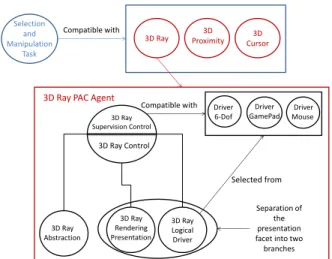
Compatible with 3D Ray Abstraction 3D Ray Rendering Presentation 3D Ray Logical Driver 3D Ray Control 3D Ray Supervision Control Selected from Driver 6-Dof Driver GamePad Driver Mouse Compatible with Separation of the presentation facet into two branches Selection and Manipulation Task 3D Proximity
Figure 6: The proposed interaction model. The task selec-tion and manipulaselec-tion is compatible with 3 interacselec-tion tech-niques. The figure represents the PAC agent of the 3D ray-based technique. This agent is compatible with three con-crete logical drivers. Multiple rendering presentations could be implemented depending on the target 3D framework. the rotation of the ray on the X and Y axes in order to con-trol the ray target. The second 2-Dof input is used to increase the ray length when a positive force is applied on the Y axis and decrease it when a negative force is applied. A discrete input is still used for object catching. The last one is based on an input of mouse type with a 2-DoF input in screen space, as shown in Figure 1b. The position is also constant at the center of the user view. To control the ray rotation, we compute the ray target as the intersection point between the far clipping plane and a ray defined by two points, the camera position and the 3D point that corresponds to the mouse position on the near clipping plane. The mouse wheel is used to increase and reduce its length and a discrete state (one button) for ob-ject catching. The 3D-ray is one interaction technique that can complete the selection and manipulation task. However, as shown in Figure 6, it is not the only one. The Figure 1c gives another example: a 3D cursor represented by a virtual hand. In that case, the logical driver used consists in control-ling a 3D cursor in position and rotation by tracking the user’s hand. To catch and object, the user has to close his hand. In this section we describe our interaction technique model that ensures device and framework independence which al-lows our toolkit to cover R1 and R2. The creation of inter-action techniques and logical drivers and the association with device units can be done automatically. It can also be con-figured seamlessly at runtime, for instance switching from a device to another one, or trying another interaction technique. Therefore the model also satisfies R3 and R4. An integrated GUI to perform the configuration could reinforce these as-pects. The automatic allocation of the interaction techniques and the configuration GUI are topics for future work.
CONCLUSION AND FUTURE WORK
In this paper, we propose two models that meet the require-ments needed to handle the plasticity property for interaction
techniques in 3D user interfaces. The first one is an extend-able device model which includes devices capabilities, limi-tations and represenlimi-tations in the real world. This model ex-poses device context changes such as the add of the removal of a device, or properties modifications. The second one is an interaction model that uses the device model, it is based on PAC and ARCH. The approach lets the developer create interaction techniques independently of concrete devices and of a 3D framework.
Future work consists in establishing and adaptation engine that will create the interaction techniques at runtime accord-ing to the current context in order to always provide the most suited application. Our models must also be extended in order to take into account different levels of adaptation such as user and content adaptation. Our perspective is to create a tool for developers and designers for the creation of plastic 3D user interfaces. Such a tool is being developed with our models in Mono C# and interfaced with the Unity3D game engine.
REFERENCES
1. A metamodel for the runtime architecture of an
interactive system: The uims tool developers workshop. SIGCHI Bull. 24, 1 (Jan. 1992), 32–37.
2. Bowman, D. A., Coquillart, S., Froehlich, B., Hirose, M., Kitamura, Y., Kiyokawa, K., and Stuerzlinger, W. 3d user interfaces: new directions and perspectives. IEEE computer graphics and applications 28, 6 (2008), 20–36.
3. Bowman, D. A., Kruijff, E., LaViola, J. J., and Poupyrev, I. 3D User Interfaces: Theory and Practice. Addison Wesley Longman Publishing Co., Inc., Redwood City, CA, USA, 2004.
4. Buxton, W. Lexical and pragmatic considerations of input structures. SIGGRAPH Comput. Graph. 17, 1 (Jan. 1983), 31–37.
5. Calvary, G., Coutaz, J., Daassi, O., Balme, L., and Demeure, A. Towards a new generation of widgets for supporting software plasticity: the ’comet’. In
EHCI-DSVIS’04(2004), 306–323. Hamburg, Germany. 6. Card, S. K., Newell, A., and Moran, T. P. The
Psychology of Human-Computer Interaction. L. Erlbaum Associates Inc., Hillsdale, NJ, USA, 1983. 7. Coutaz, J. PAC, on object oriented model for dialog
design. In Interact’87 (1987). 6 pages.
8. Florens, J.-L., Hulin, T., Gil, J. J., and Davy, P. Force feedback device / force properties. In Enaction and enactive interfaces : a handbook of terms. Enactive Systems Books, 2007, 106–108.
9. Green, M., and Lo, J. The grappl 3d interaction technique library. In Proceedings of VRST 2004, ACM (New York, NY, USA, 2004), 16–23.
10. Han, S., Han, J.-J., Kim, J. D. K., and Yeong Kim, C. Connecting users to virtual worlds within MPEG-v standardization. Signal Processing: Image
DRAFT
11. Hand, C. A survey of 3d interaction techniques. In Computer graphics forum, vol. 16 (1997), 269–281. 12. Lacoche, J., Duval, T., Arnaldi, B., Maisel, E., and
Royan, J. A survey of plasticity in 3D user interfaces. In 7th Workshop SEARIS(2014).
13. Lindt, I. Adaptive 3D-User-Interfaces. PhD thesis, 2009. 14. Lipscomb, J. S., and Pique, M. E. Analog input device
physical characteristics. SIGCHI Bull. 25, 3 (July 1993), 40–45.
15. Mackinlay, J., Card, S. K., and Robertson, G. G. A semantic analysis of the design space of input devices. Hum.-Comput. Interact. 5, 2 (June 1990), 145–190. 16. Ohlenburg, J., Broll, W., and Lindt, I. DEVAL–a device
abstraction layer for VR/AR. In Universal Acess in Human Computer Interaction. Coping with Diversity. Springer, 2007, 497–506.
17. Thevenin, D., and Coutaz, J. Plasticity of user interfaces: Framework and research agenda. In Proceedings of INTERACT, vol. 99 (1999), 110–117.