HAL Id: hal-01716120
https://hal.archives-ouvertes.fr/hal-01716120
Submitted on 4 Dec 2019
HAL is a multi-disciplinary open access archive for the deposit and dissemination of sci-entific research documents, whether they are pub-lished or not. The documents may come from teaching and research institutions in France or abroad, or from public or private research centers.
L’archive ouverte pluridisciplinaire HAL, est destinée au dépôt et à la diffusion de documents scientifiques de niveau recherche, publiés ou non, émanant des établissements d’enseignement et de recherche français ou étrangers, des laboratoires publics ou privés.
To cite this version:
Pascale Bruckel, Philippe Lours, Pascal Lamesle, Bernard Pieraggi. In situ ESEM investigations of the oxide growth on hot work tools steel: effect of the water vapour. Materials at High Temperatures, Taylor and Francis, 2003, 20 (4), pp.551-560. �10.3184/096034003782750105�. �hal-01716120�
INTRODUCTION
Tempered martensitic tools steels used in forging processes are frequently submitted to complex thermo-mechanical loading cycles combined with complex environments (wet atmosphere, lubricant, etc.). Unexpected failure of forg-ing tools can result from the combination of thermo-mechanical and chemical damage. Although the influence of environment is usually underestimated, the extensive oxidation observed on tool surfaces [1] shows that the influence of chemical damage cannot be neglected. There-fore, a better knowledge of the oxidation mechanisms of these tempered martensitic tool steels could be useful for a better understanding of their service behaviour and a better assessment of their lifetime.
The oxidation behaviour of chromia former Fe–Cr alloys has been extensively studied in dry and wet atmos-pheres, and increased growth kinetics have been reported in the presence of H2O [2–4]. For pure chromium and for
Cr2O3-forming alloys, Henry et al. [4,5] have suggested that the enhanced diffusion in wet atmosphere results from the faster transport of substitutional OH–anions compared
to the transport of O2–anions through the chromia scale
(see also [6]). At a lower chromium content, oxides grown on Fe–Cr alloys are corundum-type (Fe,Cr)2O3 solid
solution [2,7–9]. Enhanced kinetics have also been observed in the presence of water vapour. They can be related either to the presence of macroscopic defects (pores, cracks, etc.) [Lepingle et al., 7] or to the water vapour in the oxidising gas, particularly the effect of hydroxyl ions whose amount depends on the H2O/O2 ratio [Nickel et al., 8]. The detrimental effect resulting from the evaporation of CrO2(OH)2has been studied by Asteman et al. [3] for different Cr contents [9]. All these mechanisms point to a significant decrease of the chromium concentration in the oxide as Cr supply from the substrate is too low compared to the Cr depletion rate. However, the chromium content of tempered marten-sitic tools steels is about 5 wt% and does not permit the growth of a continuous and protective oxide scale [1]. This is particularly the case for modified AISI H11 steel considered in the present study.
MATERIAL AND EXPERIMENTAL
The material investigated is a tempered martensitic tool steel modified AISI H11 with Rockwell hardness 47 HRc and chemical composition reported in Table 1. The
micro-In situ ESEM investigations of the oxide
growth on hot work tools steel: effect of the
water vapour
P. Bruckel, P. Lours, P. Lamesle and B. Pieraggi
CROMeP, Research Centre on Tools, Materials and Processes, Ecole des Mines d’Albi-Carmaux, 81013 Albi, France
Tempered martensitic steel modified AISI H11 is used in forging processes where tool failure can result from the combination of thermo-mechanical and chemical damage. A better knowledge of the oxidation mechanisms in this material could be useful for a better appreciation of its service behaviour and life-time. The low chromium content of this Fe–Cr type steel allows the development of mainly Fe2-xCrxO3 oxides with corundum structure and leads to enhanced oxidation in the presence of water vapour.
In situFEG–ESEM images show the scale microstructural modifications during high temperature exposure, as well as the lateral growth of oxide particles. Together with GIXRD, SEM/EDS and SIMS analysis, FEG–ESEM also allows assessment of the H2O effect on oxidation behaviour during high temperature exposures (600 and 700°C). Water vapour induces either pores or crystallites size increase, favours faceted oxides particles with enhanced density at the highest partial pressure. At this microscopic scale, anisotropic growth of crystallites is observed, and size expansion rates are found to be linear and characteristic of each individual particle.
Temperature acts principally on oxide film microstructure. Whatever the environment, homogeneous scale growth is observed at 600°C whereas the steel surface is heterogeneously covered by oxides at 700°C.
Keywords: environmental scanning electron microscopy, oxide growth, water vapour, steel oxidation
*To whom correspondence should be addressed: E-mail: bruckel@enstimac.fr
structure consists of martensitic laths (0.1–2 !m width and 0.5–15 !m length) and of carbides segregated at the grain boundaries [10]. Specimens are cut into rectangular pieces with dimensions (25 mm " 8 mm " 3 mm) for thermogravimetric analysis and (2.5 mm " 2.5 mm " 3 mm) for in situ FEG-ESEM observations. After polish-ing down to 3 !m, samples are cleaned in an ultra-sonic ‘50% acetone + 50% ethanol’ bath and dried in hot air.
Oxidation treatments consist of exposures at 600 or 700°C for 160 hours carried out in a thermo gravimetric analyser (TGA). The oxidising media are either dry gas (synthetic air with maximal water content of 3 ppm H2O, called OA1), or wet gas (synthetic air + 19.7 or 30.8 vol.% H2O, called OA2 and OA3), and are described in Table 2. Analysis of scale morphology and chemical composition are performed using scanning electron micro-scopy with energy dispersive spectrometry (SEM/EDS), by Grazing Incidence X-ray diffraction (GIXRD) carried out for different grazing angles (0.1°, 0.5°, 1° and 5°), and by secondary ion mass spectrometry (SIMS) where the secondary MCs+-ions are detected to avoid matrix effect. In situinvestigations of the scale growth are performed using a field emission gun – environmental scanning electron microscope (FEG-ESEM) coupled to a high– temperature stage. The tests take place at 600 and 700°C in both dry and wet environments (Table 2). The dry atmosphere (OA4) is simply the laboratory air whereas the wet atmosphere consists in nitrogen and water vapour of controlled partial pressure varying from 50 to 100 Pa (OA5, OA6, AO7). Prior to isothermal exposure, the specimens are heated in nitrogen to prevent any oxi-dation at low temperatures. The images are formed by using a gaseous secondary electron (GSE) detector. Finally, SEM is used for post mortem analysis of the morphology and microstructure of the oxide scales grown in situ. OXIDATION KINETICS
Thermogravimetric curves obtained for exposures at 600 and 700°C in either dry or wet environment are shown in Figure 1. At 600°C in the presence of water vapour, parabolic behaviour is observed for oxidation treatments in respectively air + 19.7 vol.% H2O (!) and air + 30.8
vol.% H2O ("). The resulting weight gains are signifi-cantly higher than in dry air (") where the kinetics may
also fit a parabolic law while the grown oxide scale is very thin, as indicated by the very low mass increase (0.1 mg cm–2for 160 hours exposure).
Enhancement of the oxidation kinetics is also appreci-able at 700°C as shown in Figure 1. Once again, mass gain is much more pronounced in a wet atmosphere (21.3 mg cm–2 after 90 hours exposure in air + 19.7 vol.% H
2O)
than in dry air (6.6 mg cm–2after 90 hours). The shape of
the curve monitored during oxidation at 700°C for 160 hours in dry conditions is first parabolic then, after 10 hours, exhibits a sudden slope increase and levels off again to a parabola after 35 hours exposure. The temper-ing temperature of tools steels is about 620°C, thus microstructural changes of the underlying substrate may occur during oxidation treatments for 160 hours at 700°C. In contrast, the kinetics are approximately parabolic over the full duration (90 hours) of exposure at 700°C in air + 19.7 vol.% H2O.
An assessment of the relative effect of water vapour and temperature may be obtained by comparison of the kinetics in wet atmosphere at 600°C (!) (") and in dry
air at 700°C (#). Up to 40 hours, oxidation resistance
seems to be mainly related to the presence of water vapour. For longer time, the temperature effect becomes predominant as mass gain is lower after wet oxidation at 600°C than after dry oxidation at 700°C. It can be finally concluded from the data in Figure 1 that growth rates are connected to the temperature whose drastic effect on weight gain is particularly observed after long time exposures. Moreover, oxidation kinetics are significantly increased in the presence of water vapour and tend to be parabolic.
OXIDE SCALE CHARACTERISATION
After oxidation in dry air at 600 or 700°C, GIXRD diffraction peaks (Figures 2a and 2b) are characteristic of the underlying steel substrate and of hematite #-Fe2O3. Nevertheless, the observed peaks of hematite are shifted from their theoretical Fe2O3position given by the JCPDS
card number 33–664. This shift is related to the presence of chromium in hematite. Actually, #-Fe2O3, #-(Fe,Cr)2O3
and Cr2O3 have the same corundum structure type and similar lattice parameters so that substitution of Fe by Cr in hematite is possible. The oxidation product is expressed as Cr-substituted hematite Fe2-xCrxO3.
For specimens exposed at 600°C for 160 hours in dry air, MCs+-SIMS depth profiles (Figure 3) exhibit a
decrease in the Fe content and a corresponding increase of the Cr content close to the substrate/oxide interface confirming that chromium substitutes for iron in #-Fe2O3.
Note also the enrichment in Mn and Mo in this inner part of the oxide film whereas the outer part is mainly hematite with a slight amount of manganese whose con-tent gradually decreases from 9 at% at the gas/oxide inter-face to 0.5 at% at the interinter-face between #-Fe2O3 and Fe2–xCrxO3. These values must be handled with care since
the actual profiles of Fe, Cr, Mn and Mo in the oxide part
Table 1 Chemical composition of modified AISI H11 tool steel
Fe C Cr Si Ni Mn V Mo
Modified Bal. 0.36 5.70 0.35 0.09 0.40 0.47 1.25 wt% AISI H11 Bal. 1.65 6.03 0.68 0.08 0.40 0.51 0.72 at%
Table 2 Description of the different oxidising atmospheres (at 20°C)
TGA FEG-ESEM
Literal denomination Dry air Air + 19.7 Air + 30.8 Laboratory air N2+ 100 Pa H2O
vol% H2O vol% H2O (50% Relative
Humidity) N2+ 50 Pa H2O
Total pressure 101300 Pa 190 Pa 130 Pa 200 Pa 250 Pa
H2O partial pressure 30 Pa 19956 Pa 312000 Pa 14 Pa 50 Pa 100 Pa
Vol% H2O 3 ppm 19.7% 30.8% 8% 38.5% 25% 40%
have been plotted using relative sensitivity factors (RSF) estimated with the following approximations : (i) RSF of oxygen is not included in the calculation and (ii) RSF is assumed constant in the substrate and the oxide. This calculation is based on the elementary chemical compo-sition of the substrate and the corresponding MCs+
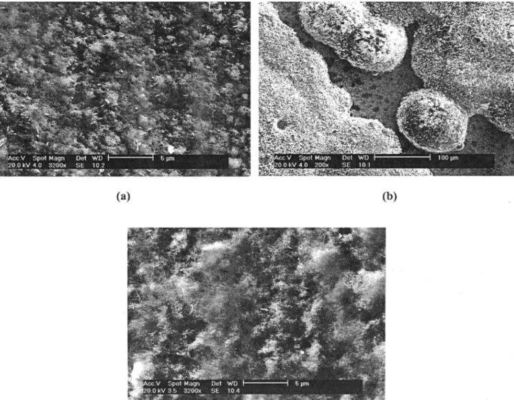
-SIMS intensities [11]. Note that after 160 hours exposure at 600°C in dry air, the steel surface is fully covered by the grown scale which shows a porous morphology whereas no crystallites can be precisely distinguished (Figure 4a). Furthermore, and according to the TGA results (Figure 1) and the presence of steel peaks in GIXRD patterns (Figure 2a), the oxide film is supposed to be very thin (less than 1 !m).
After exposure at 700°C for 160 hours in dry air, a duplex structure of the oxide film is observed showing a thin inner scale that is, from EDS analysis, rich in chromium and other alloying elements like Mo, Mn, V or Si, and an outer homogeneous layer that probably results from the coarsening and coalescence of hemis-pherical islands (~100 !m) that are shown in Figure 4b. Globally, the heterogeneity of the oxide film leads to complex X-ray diffraction responses where both the duplex oxide scale and the underlying steel diffract (Figure 2b).
If the composition of the oxide film seems unchanged regardless of the oxidation temperature, the morphology of the oxidised surface changes : the homogeneity of the scale formed at 600°C is no longer achieved at more elevated temperatures. Since 700°C is higher than the tempering temperature, the scale heterogeneity shown in Figure 4b may be related to the loss of the pure tempered martensitic microstructure due to high-temperature long-time exposure of the steel substrate. This evolution leads to a new structure that may favour localised oxidation as diffusion paths usually follow grain boundaries. Conversely, diffusion in the initial steel microstructure occurs at the more closely connected martensitic lath boundaries resulting in a homogeneous scale.
In the presence of water vapour, especially for oxida-tion at 600°C in dry air + 19.7 vol.% H2O (OA2) for 160 hours and in dry air + 30.8 vol.% H2O (OA3) for 90
hours, only Fe2-xCrxO3is observed in Figures 2c and 2d.
No steel peak (#-Fe) occurs on the GIXRD patterns indi-cating, in agreement with kinetics results in Figure 1, that the oxide films grown in wet atmospheres are, for the same exposure time and temperature, much thicker than those formed in the dry environment. A significantly
increased porosity (~1 !m) is observed compared to dry oxidation (~200 nm) (Figure 4c). Finally, the initial steel surface is homogeneously covered by oxides except locally scaled areas exhibiting another morphology and crack networks.
Figure 1 Oxidation kinetics for different oxidising conditions (")
600°C in dry air (#) 700°C in dry air (!) 600°C in air + 19.7%vol H2O (") 600°C in air + 30.8%vol H2O ($) 700°C in air + 19.7%vol
H2O.
Figure 2 GIXRD patterns (grazing angle 5°) after exposure for 160
hours at (a) 600°C in dry air (b) 700°C in dry air (c) 600°C in air + 19.7 vol.% H2O, and for 90 hours exposure at (d) 600°C in air + 30.8
vol.% H2O (e) 700°C in air + 19.7 vol.% H2O. Circles (%) stand for
After exposure at 700°C in air + 19.7 vol.% H2O (OA2)
for 90 hours, GIXRD patterns exhibit Cr-substituted hema-tite for each analysed angle (0.1°, 0.5°, 1° and 5°) and additional diffracted peaks characteristic of Fe3O4 for grazing angle 5° (Figure 2e). The grown oxide scale is thus assumed to be composed of an outer Fe2-xCrxO3 scale and an inner magnetite layer. No significant shift of the Fe3O4peaks has been observed but it may be assumed
that the mixed iron-chromium spinels mentioned in litera-ture [2] also occur. Oxide spallation upon cooling results in a strong embrittlement of the oxide layer and further analysis (SEM, SIMS, etc.) have not yet been performed. FEG-ESEM IN SITU OBSERVATION OF THE OXIDE GROWTH
FEG-ESEM equipment permits in situ study of the oxidation of specimens at high temperatures (600 and 700°C) by using a specific heating stage. The oxidation can be performed either in laboratory air or in nitrogen + water vapour. This is useful for investigating the effect of H2O on oxidation behaviour of the studied material. Images are obtained using emitted gaseous species (GSE detector). Many technical constraints must be considered to produce good quality images. First, the electrical con-ductivity of species is lowered in dry atmospheres com-pared to wet environments, which makes image acquisition more difficult. In addition, in wet environments, heating of specimens is performed using a N2 atmosphere to avoid low temperature oxidation but no image can be recorded in this case. Although electrical conditions are better in wet environments, the high working tempera-ture leads to important image shifts on the screen and makes good adjustments difficult. Furthermore, thermal expansion of the material is an additional source of
Figure 3 MCs+-SIMS concentration profiles for 160 hours exposure
at 600°C in dry air. (&) iron (") chromium (") molybdenum (%) manganese.
Figure 4 SEM images of the oxide scale formed after exposure (a) at 600°C for 160 hours in dry air (b) at 700°C for 160 hours in dry air (c) at
focussing difficulty and hinders accurate recording of specific zones of interest over oxidation exposure. OXIDE GROWTH AT 600°C
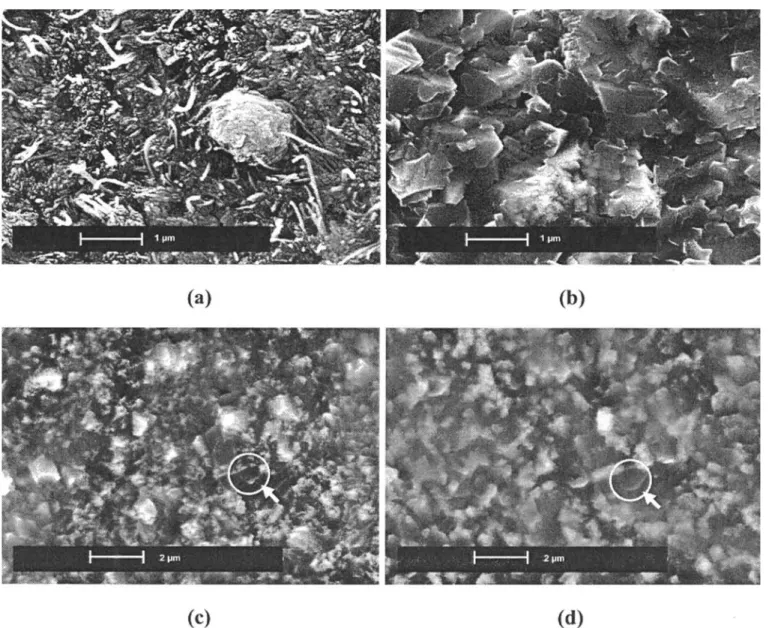
Figure 5 presents a few characteristic post mortem images after oxidation either in dry or wet atmosphere was com-pleted (Figures 5a and b) and during in situ oxidation in the FEG-ESEM (Figures 5c and d). The morphology of the oxide scale formed during exposure at 600°C in dry conditions (OA4) for 2 hours consists of a continuous layer on which globular crystallites are located (Figure 5a). Those particles, with dimensions of about 1 !m, are observed in situ as soon as image recording starts, but with a smaller size (~ 500 nm), suggesting that they form during the very early stages of oxidation. Only a little change of shape of the globular oxides is observed dur-ing exposure. However, the evolution of the surrounddur-ing scale can be followed in situ and exhibits a very slow growth rate in agreement with kinetic results discussed in the corresponding section. Finally, the continuous scale is composed of agglomerated nano-crystallites and of hematite whiskers.
Figure 5b shows a post mortem image of the surface oxidised in wet conditions at 600°C for 45 minutes (OA5). Again, globular oxides are present when the observation starts and it is assumed that quite similar nucleation pro-cesses occur in dry and wet atmospheres. The initial metal surface is totally covered by a scale that has developed around the initial globular oxides which are more or less overlapped by micrometre-sized faceted crystallites. No hematite whiskers are observed in this case. Figures 5c and d describe in situ evolution of the oxide scale with time for exposure in 50 Pa H2O. The main feature
observed in this dynamic sequence is the drastic change of scale morphology over a short time scale (10 minutes) resulting from a rapid coarsening of oxide crystallites. OXIDE GROWTH AT 700°C
At 700°C in FEG-ESEM experiments, the oxide scale produced upon thermal exposure in the dry environment (OA4) is heterogeneous (Figure 6), according to the obser-vations presented in Figure 4b, and for the same metal-lurgical reasons previously discussed (tempering temper-ature below 700°C). However, the morphology of the scale
Figure 5 Post-mortem SEM images of the oxide scale formed after exposure at 600°C (a) for 2 hours in laboratory air (b) for 45 minutes in 50 Pa
water vapour. In situ ESEM sequence showing surface evolution during oxidation at 600°C under wet conditions (c) after 32 minutes exposure (d) after 42 minutes exposure.
is somewhat different as the oxidising conditions are different in the TGA and FEG-ESEM tests (laboratory air versus dry air, 2 hours versus 160 hours). The result-ing scale consists of the initial surface slightly oxidised except for a few isolated circular areas with diameter in the range 30–40 !m where globular crystallites are located (Figure 6) and no hematite whiskers are observed.
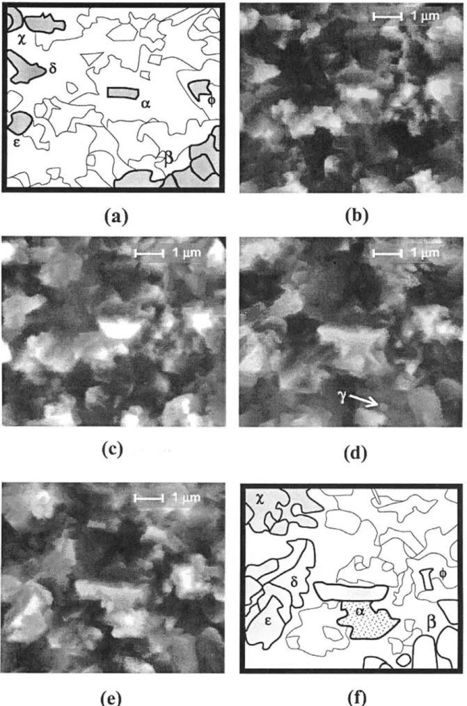
In the presence of water vapour (50 Pa H2O), the oxide layer is subject to microstructural changes as indicated in the in situ sequence of Figure 7. The oxide film has grown for 1 hour 15 minutes prior to being monitored in situ for 10 minutes. The morphology of the scale is significantly modified during this rather short time period indicating faster oxidation kinetics than in dry air. The growth of typical oxide crystallites, such as those labelled #and $, with simple forms, seems essentially bi-directional and exhibits some anisotropy in the plane of observation. Other oxide particles of complex shapes (labelled %, &, ' or () tend to grow in a complex way. Conversely, some other particles (marked ), * or +) do not coarsen at all during the sequence.
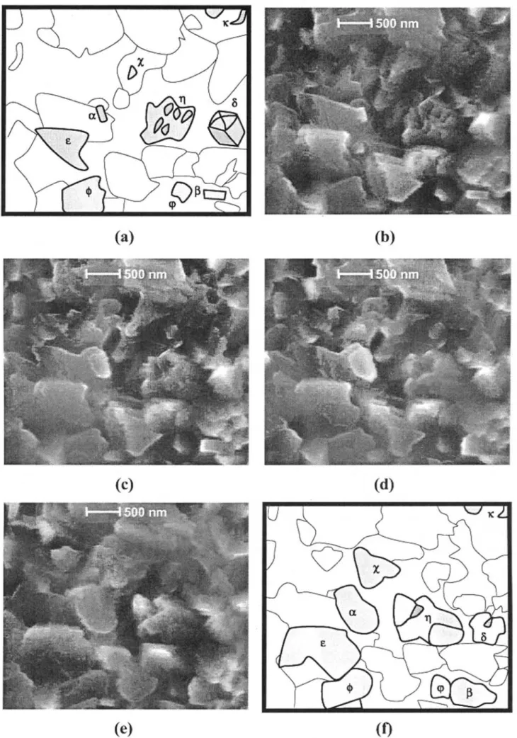
The isothermal experiment at 700°C in wet conditions consists of a two-step exposure, first under 50 Pa partial pressure of water vapour for 2 hours (OA6), then under 100 Pa H2O for 3 hours (OA7). Figure 8 shows a sequence of images starting after 1 hour 35 minutes under the former environment. Enhanced modifications of the oxidised surface are observed as soon as the water vapour partial pressure is increased. Larger amounts of crystallites are present that gives rise to a more complex scale showing higher crystallite density and seemingly enhanced compactness. Attention may be paid to the particle labelled #whose size increase is particularly sig-nificant. The crystallite gradually loses its initial rectan-gular form (Figure 8b) to develop first into a trapezoid with faceted edges (Figure 8c). After about 30 minutes growth, coalescence occurs with an oxide particle located underneath leading to a new shape particularly apparent
in Figure 8d. Further growth tends to develop again into a rectangle. The growth of this particle preferentially proceeds toward the left hand side and the bottom of the image confirming the growth anisotropy previously dis-cussed. Its final shape is highly irregular (Figure 8e) and its length, measured parallel to the horizontal of the images, increases by 300% over 1 hour exposure under 100 Pa H2O at 700°C. Though much more difficult to monitor, but nevertheless interesting, is the evolution of particles in the areas marked %, ) and &: coalescence occurs as crystallites tend to coarsen and join to each other when growing. Changes for the $-particles are also remarkable: from an initial complex form, particles trans-form into a more regular shape with rounded edges. Similarly as for experiments under 50 Pa partial pressure of water vapour previously described, some particles, for instance ,, only show little evolution during the sequence: instead of growing, this particle seems to collapse to the benefit of new oxides. The total duration of the exposure in 100 Pa water vapour (OA7) at 700°C is 3 hours, and the sequence in Figure 8 deals with a time period between 1 hour 35 minutes and 2 hours 25 minutes. The further exposure (35 minutes) leads to the development of faceted oxides. Finally, a post mortem image in Figure 9 shows a heterogeneous scale with two morphologies: a very thin layer composed of nano-crystallites coexisting with compact and faceted oxides of average size 1 !m. No hematite whisker growth was followed in situ. CRYSTALLITES GROWTH KINETICS
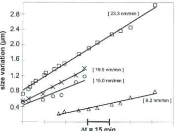
Figure 10 shows the evolution of typical crystallite dimen-sions during in situ oxidation at 700°C in 100 Pa partial pressure of water vapour (OA7). In practice, relevant size parameters of crystallites are measured, for instance length and width of rectangular particles. However, the initial morphology usually changes during oxide growth so that a given dimension cannot be followed over the whole exposure time. In such a case, another specific para-meter is chosen for measurement. In situ observations show that the nucleation of crystallites may occur at any time during exposure. An example is given in Figure 8d where the particle marked , clearly nucleates within the preced-ing time period. For this reason, no time origin is shown in Figure 10 and only the time scale -t is indicated.
In Figure 10, squares (!) stand for the length of
the particle labelled # (Figure 8) whose size has been measured from the start till the end of the in situ sequence. Triangles (#) represent the width of the rectangular part
that develops after the coalescence of # with another crystallite in the time period between Figures 8c and 8d. Experimental data fit satisfactorily single regression lines. Crosses (") and circles ($) are relative to the growth of another, egg-shaped, crystallite not shown in Figure 8 and labelled .. In this case, linearity of the size-versus-time curves is also achieved. However, some dispersion is observed resulting from alternate increase periods of respectively the major and the minor axis of the ellipsoid. This can again be related to the previously mentioned growth anisotropy.
If similar linear growth mechanisms are pointed out for several crystallites, slopes of size-versus-time curves are quite different. Thus, a single linear kinetic law describ-ing the growth of all the crystallites cannot be assumed. Growth rates for exposure at 700°C in 100 Pa H2O are in the range 5–25 nm min–1 which is smaller than growth
Figure 6 Post mortem SEM image of the oxide scale formed after
Figure 7 In situ FEG-ESEM images showing oxides growth in 50 Pa partial pressure of water vapour at 700°C. Recording starts after 1h15min
Figure 8 In situ FEG-ESEM images showing oxides growth under 100 Pa partial pressure of water vapour at 700°C after previous exposure for 2
hours in 50 Pa H2O. Monitoring starts after 1h35min exposure (t = 0 min). (a) schematic of (b), (b) t = 0 min (c) t = 15 min (d) t = 45 min (e) t = 60
rates for oxidation in 50 Pa water vapour (30–50 nm min–1). Calculation of this latter growth rate range is
based on data obtained from a short time in situ sequence (10 minutes) after approximately 1 hour oxidation in 50 Pa H2O (OA6). Since the total duration of this
treat-ment in OA6 is 2 hours, the conservation of a linear behaviour during the remaining 1 hour exposure cannot be ensured. Further oxidation may lead to slower kinetics with, for instance, parabolic or cubic behaviour. In this case, decreased linear growth rates in 100 Pa H2O (OA7)
are due to the presence of the oxide film formed during the previous 2 hours exposure in 50 Pa H2O (OA6). This
scale acts as a barrier to the transport of cations, and limits the reaction with the oxidising atmosphere. Another possible reason for the slowing down of crystallite growth rates, is an increase of the number of nucleation sites. This is in good agreement with the crystallite density that is enhanced as water vapour partial pressure increases from 50 to 100 Pa, and with the observation of some particles that either remain constant in size during exposure, or collapse to form new crystallites. In addition, the increase of H2O partial pressure (OA7) seemingly modifies the morphology of the grown oxide scale and therefore induces a change in oxidation mechanisms.
CONCLUSIONS
The literature suffers a lack of information about the oxide films developed on tool steels during exposure at high temperatures. Since these complex oxides may get involved in the forging tools chemical damage, a better understanding of the initial stages of oxide growth on these materials is of the highest importance. FEG-ESEM is particularly suitable for performing in situ investigations under controlled conditions of temperature (600 and 700°C) and atmosphere (laboratory air, water vapour,
etc.). This equipment allows observation of the lateral growth of some crystallites and of the scale micro-structural changes. Finally, the water vapour effect on oxide growth can be investigated if FEG–ESEM is added to more conventional post mortem techniques such as GIXRD, SEM/EDS or SIMS.
In situFEG–ESEM observations exhibit the formation of nano-sized particles in dry environment and micro-crys-tallites for wet oxidation. This is in good agreement with the post mortem SEM investigations that show globular nano-crystallites form in laboratory air whereas faceted crystallites (micrometre size) preferentially develop in the presence of water vapour. TGA results obtained from sam-ples oxidised in either ‘dry air’ or ‘air + H2O’ show an increase of pore size in the presence of water vapour. These microstructural differences (crystallites/ pores) between FEG-ESEM and TGA tests are related to the characteristics of the oxidising conditions (atmosphere and exposure time).
Kinetics are always enhanced in the presence of water vapour. The crystallite size expansion is found to be linear (FEG–ESEM) though the thickness increase with time fits a parabolic law (TGA). In addition, each growth direction exhibits a specific oxidation rate indicating growth anisotropy. In the particular case of wet oxidation at 700°C, growth rates are globally reduced as water vapour pressure increases from 50 to 100 Pa. This can be related to either the oxide scale formed during the earliest exposure in 50 Pa H2O for 2 hours and which may act as a diffusion barrier, or to an enhanced number of oxides due to a multiplication of the nucleation sites.
Finally, the temperature effect on oxidation behaviour is linked to the material microstructure and seems inde-pendent of the oxidising atmosphere. Modified AISI H11 is a tempered martensitic tools steel with tempering tem-perature about 620°C. For instance at 600°C, stability of the microstructure is assumed and the relatively good closeness of the laths’ boundaries allows an homogeneous scale to grow. In contrast, possible transformations of the underlying steel microstructure for long time exposure at 700°C can lead to more widely spaced short-circuit dif-fusion paths and explain the observed heterogeneity of the grown oxide films.
Further investigations will first attempt to validate kinetics linearity over longer exposure times with the aim (i) to give ranges for the growth rates in both dry or wet oxidising conditions, (ii) to clarify the low expan-sion rates found for exposure at 700°C in 100 Pa water vapour. On the other hand, oxidation kinetics enhance-ment in the presence of water vapour has not been corre-lated to any drastic Cr depletion in the underlying sub-strate, especially in our case as iron seems to be, however, preferentially oxidised. Hypotheses on the presence of pores / cracks [7], the increase of the OH–content in the
scale [4–6,8] or the evaporation of Cr / Fe hydroxides [3,9] will be more precisely investigated in future work.
Figure 9 Post mortem SEM image of the oxide scale formed after
exposure at 700°C for 2 hours under 50 Pa H2O and further 3 hours
under 100 Pa H2O.
Figure 10 Size variation of oxides grown on a surface first oxidised at
700°C for 2 hours in 50 Pa H2O then in 100 Pa H2O. Linear regression
curves are shown in full lines. (!) length of crystallite #(#) width of crystallite #(") long axis of crystallite . ($) short axis of crystallite ..
REFERENCES
[1] Jean, S. Méthodologie d’exploitation mécanique et microstructurale d’un essai de fatigue thermique: application à l’étude du faïençage d’un acier pour outil de forge à chaud. Thesis, Institut National Polytechnique de Toulouse (1999).
[2] Kofstad, P. High temperature corrosion. Elsevier Applied Science, London & New York, (1998).
[3] Asteman, H. Svensson, J.-E. Johansson, L.-G. and Norell, M. Indi-cation of chromium oxide/hydroxide evaporation during oxidation of 304 L at 873 K in the presence of 10% water vapour. Oxidat. Metals
52(1/2), 95–111 (1999).
[4] Henry, S. Influence de la vapeur d’eau sur l’oxydation à haute température du chrome et de quelques aciers inoxydables ferritiques stabilisés. Thesis, Institut National Polytechnique de Grenoble (2000).
[5] Henry, S. Mougin, J. Wouters, Y. Petit, J.-P. and Galerie, A. Characterization of chromia scales grown on pure chromium in different oxidising atmospheres. Mater. High Temp. 17(2), 231–235 (2000).
[6] Galerie, A. Wouters, Y. and Caillet, M. The kinetic behaviour of metals in water vapour at high temperatures: can general rules be proposed?
Mater. Sci. Forum369–372, 231–238 (2001).
[7] Lepingle, V. Louis, G. Petelot, D. Lefebvre, B. Vaillant, J.-C. High temperature corrosion behaviour of some boiler steels in pure water vapour. Mater. Sci. Forum 369–372, 239–246 (2001).
[8] Nickel, H. Wouters, Y. Thiele, M. Quadakkers, W.J. The effect of water vapour on the oxidation behaviour of 9%Cr steels in simulated combus-tion gases. Fresenius’ J. Analyt. Chem. 361(6/7), 540–544 (1998). [9] Asteman, H. Segerdahl, K. Svensson, J.-E. Johansson, L.-G. The
influence of water vapour on the corrosion of chromia-forming steels.
Mater. Sci. Forum369–372, 277–286 (2001).
[10] Delagnes, D. Comportement et tenue en fatigue isotherme d’aciers à outils Z38CDV5 autour de la transition oligocyclique – endurance. Thesis, Ecole des Mines de Paris (1998).
[11] Pfeifer, J.-P. Holzbrecher, H. Quadakkers, W.J. Breuer, U. Speier, W. Quantitative analysis of oxide films on ODS-alloys using MCs+-SIMS and e-beam SNMS. Fresenius’ J. Anal. Chem. 346(1/3), 186–191 (1993).


![[PDF] Apprendre à creer des objets intelligents avec Arduino pdf | Cours gratuit](data:image/gif;base64,R0lGODlhAQABAIAAAP///wAAACH5BAEAAAAALAAAAAABAAEAAAICRAEAOw==)