HAL Id: hal-01968735
https://hal.archives-ouvertes.fr/hal-01968735
Submitted on 10 Mar 2020HAL is a multi-disciplinary open access
archive for the deposit and dissemination of sci-entific research documents, whether they are pub-lished or not. The documents may come from teaching and research institutions in France or abroad, or from public or private research centers.
L’archive ouverte pluridisciplinaire HAL, est destinée au dépôt et à la diffusion de documents scientifiques de niveau recherche, publiés ou non, émanant des établissements d’enseignement et de recherche français ou étrangers, des laboratoires publics ou privés.
Monitoring gas hydrate formation and transport in a
flow loop with acoustic emission
Ana Cameirão, Eric Serris, Aline Melchuna, Jean-Michel Herri, Philippe
Glenat
To cite this version:
Ana Cameirão, Eric Serris, Aline Melchuna, Jean-Michel Herri, Philippe Glenat. Monitoring gas hydrate formation and transport in a flow loop with acoustic emission. Journal of Natural Gas Science and Engineering, Elsevier, 2018, 55, pp.331 à 336. �10.1016/j.jngse.2018.04.035�. �hal-01968735�
1
Monitoring gas hydrate formation and transport in a flow
loop with acoustic emission
CAMEIRAO A.a,*, SERRIS E.a, MELCHUNA A.a, , HERRI J.M.a, GLENAT P.b
a Centre SPIN, Département Propice, Laboratoire LGF (UMR 5307), Ecole Nationale Supérieure
des Mines de Saint-Etienne, 158 Cours Fauriel, Saint-Etienne 42023, France
b TOTAL S.A., CSTJF, Avenue Larribau, Pau Cédex 64018, France
*corresponding author: cameirao@emse.fr ABSTRACT
Experimental studies on flow loop allow estimating the amount of formed hydrate and their transport during time. The amount of hydrates formed spatially during flow is unknown together with the location of the beginning of sedimentation and plug. This experimental study was carried on to verify the use of acoustic emission (AE) to spatially follow the formation of hydrates but also sedimentation and agglomeration. The acoustic emission energy variations allowed to follow the emulsification, to identify the beginning of the crystallization and to follow the crystallization, agglomeration and plug/sedimentation in the flow loop.
KEYWORDS: acoustic emission, gas hydrates, crystallization, liquid-liquid dispersion, rheology, agglomeration
1. INTRODUCTION
The flow assurance domain concerns different types of technology used to ensure flow at onshore and offshore pipelines. Pipeline flow is altered by presence of different types of solids (wax, scale, hydrates…). Specifically concerning hydrates, their formation can slow down and even completely stop the flow in the pipeline [Sloan et al., 2011).
In order to prevent the stop of the flow and subsequent losses on production; several mitigation measures can be envisaged. The oldest ones are pipe thermal insulation and injection of methanol to displace the formation conditions into more severe ones. The high cost of these solutions leads the researchers to search new solutions. The recent measures include the use of low dosage hydrate inhibitors like anti-agglomerant and kinetic inhibitors. These will, respectively, prevent agglomeration between hydrates and slow down or prevent completely their formation. Another solution is cold flow, it consists without injection of any chemical on allowing formation of hydrate particles which are transportable as a slurry and do not deposit or agglomerate [Sintef, 2010]. Several researchers are studying associations between these mitigation procedures.
Gas hydrates are composed by water molecules connected through hydrogen bridges forming a cage that accommodates a gas molecule [Sloan, Koh, 2007]. In this study, the focus will be on methane hydrates.
The methane hydrates crystallization can be carried on a batch reactor, a cell or a flow loop [Sloan, Koh, 2007]. Experiments on flow loop allow the study of the crystallization under flow followed by the study of the slurry transport [Melchuna et al., 2016]. Hydrate formation in flow loops are closer to real field conditions. Although, as well as it happens in field scale, a major issue is the processes along the pipeline during time. This paper presents a preliminary study with a non-intrusive technique, acoustic emission, which allows to follow hydrate formation in pipelines.
2
This technique was already used by other authors in order to understand the flow pattern in multiphase flow [Husin et al., 2013] and to detect the presence of sand and droplets in pipelines [El-Alej et al., 2014]. The idea of this work is to follow the hydrates formation from the beginning of the crystallization, detected by an increase in the energy [Gherras et al., 2012] and the hydrates crystallization with increasing solid fraction during time and during flow in the pipeline.
2. MATERIAL AND METHODS 2.1. Materials
The materials are:
- ultrapure water (provided from Millipore filter),
- oil phase is Kerdane® (C11-C14) provided by TOTAL FLUIDES®, - anti-agglomerant additive provided by TOTAL,
- pure methane (99.99%) supplied by AIR LIQUIDE. 2.2. Equipment
The Archimedes flow loop is composed by one horizontal section and one vertical section. It reproduces the thermodynamic deep-sea conditions with temperature control ranging from 0°C to 14° and pressure control up to 100 bar. The horizontal section of 1.02 cm internal diameter (2/5 inch) has 36.12 m long. The vertical section or riser of 10 m high going into a gas-liquid separator (2 m) is followed by a descending pipe of 10 m long going back down to the horizontal section. The vertical section has an internal diameter of 1.73 cm (2/3 inch) (3). The gas/liquid separator at the top of the flow loop is where the gas diffuses into the liquid phase by formation of a geyser.
The flow is induced by a multiphase pump (Moineau pump), with a flow rate between 72 L.h-1
and 500 L.h-1 (0.3 m.s-1 to 1.8 m.s-1). The flow rate is monitored with a Coriolis flow-meter
equipped with a densimeter.
The flow loop is equipped with a FBRM probe (Focused Beam Reflectance Measurement) installed on the descending pipe and a PVM probe (Particle Vision and Measurement) installed on the horizontal section, both in situ probes. As recommended for a representative sampling of the particles, probes were installed on straight pipes. The windows of these probes cut the streamlines at an angle of 45° and reach the center of the pipes (14). The FBRM probe measures the chord length of droplets, hydrate particles and agglomerates up to 1 cm. The PVM probe allows the direct observation of droplets, hydrates particles and agglomerates. A pressure probe together with nine temperature and five differential pressure probes scattered in the flow loop follow the time evolution of the processes during the experiment [Melchuna et al., 2016].
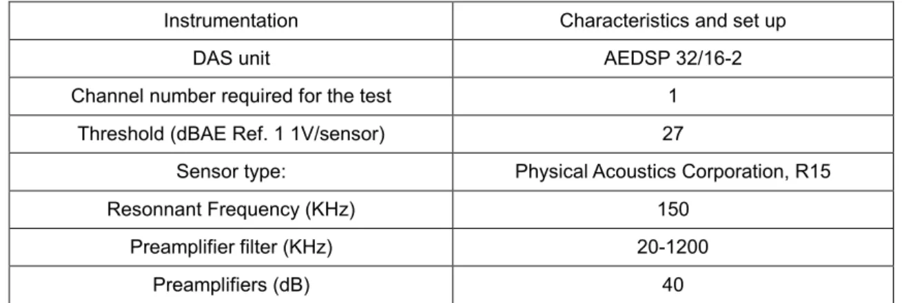
The acoustic emission (AE) probe was located at the beginning of the flow loop horizontal section. The AE signal was detected by a specific device (Physical Acoustics Corporation, R15). Coupling grease was used between the loop wall and the sensor for improving the transmitting efficiency of acoustic signals. The collected signals by the detecting device were then conditioned, amplified, filtered, and processed with a Data Acquisition System (DAS from EuroPhysical Acoustics S.A). To avoid the disturbance of signals from background, the threshold of detection was set at a high level. The parameters of the Data Acquisition System for the experiment were set as the following indicated in Table 1.
3
Table 1 Characteristics and set-up parameters for the AE acquisition system.
Instrumentation Characteristics and set up
DAS unit AEDSP 32/16-2
Channel number required for the test 1
Threshold (dBAE Ref. 1 1V/sensor) 27
Sensor type: Physical Acoustics Corporation, R15
Resonnant Frequency (KHz) 150
Preamplifier filter (KHz) 20-1200
Preamplifiers (dB) 40
The absolute energy, in atto-Joule (1 aJ = 10−18 J) is defined from the integration (in this case T=1s) of the output voltage V(t) of the transducer, and being inversely proportional to the electrical resistance of the measuring circuit.
The experiments were made with mixtures of water and kerdane with water cut (volume percentage on the liquid-liquid dispersion) equal to 40% and 80% and a flow rate fixed at 200 L.h-1 or 400 L.h-1, with and without 0.005% volume AA-LDHI vs. water. The AA-LDHI was
intentionally under-dosed to have some agglomeration and study the transport in the presence of agglomerates. During the hydrate formation, the pressure is maintained constant equal to 80 bar through a system of gas injection, composed of a pressure controller coupled to a gas flowmeter.
The conversion of the water and volume of hydrates were calculated from Melchuna et al. [Melchuna et al., 2016].
2.3. Experimental Procedure
The mixture of oil and water is injected in the flow loop. In case of experiments with additive, it is injected together with the water. The mixture is flowed on the loop until the pressure drop and the average chord length reach stability which means the dispersion is formed (3). Then the flow loop is cooled down until 4°C (which means a sub cooling of 6°C) and then the pressure is increased up to 80 bar by methane injection and the pressure compensation is turned on.
The conversion is calculated from the total amount of gas injections once the crystallization started, which is detected by the appearance of a peak in the temperature. This peak corresponds to the exothermic phenomena of the crystallization.
3. RESULTS AND DISCUSSIONS
The main experimental results are the acoustic energy together with the pressure drop and the cumulated chord length for droplets, crystallized droplets and agglomerates.
The presence of AA-LDHI at low dosage is not significant to the behavior of the crystallization and subsequent agglomeration.
4
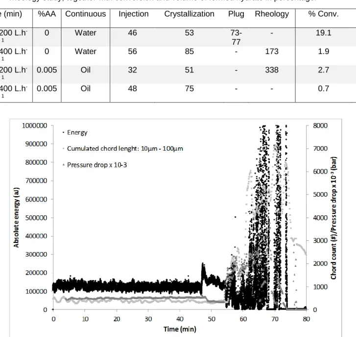
Table 2 – Times of gas injection, beginning of crystallization, plugging and beginning of the rheology study, together with conversion and volume of formed hydrate in percentage.
Time (min) %AA Continuous Injection Crystallization Plug Rheology % Conv. %
Vol. 40%, 200 L.h -1 0 Water 46 53 73-77 - 19.1 10.5 40%, 400 L.h -1 0 Water 56 85 - 173 1.9 1.0 80%, 200 L.h -1 0.005 Oil 32 51 - 338 2.7 2.8 80%, 400 L.h -1 0.005 Oil 48 75 - - 0.7 0.7
Figure 1 - Energy, chord length and pressure drop during time for experiment at 40 % water cut with 200 L.h-1 (injection, onset.
5
Figure 2 - Energy, chord length and pressure drop during time for experiment at 40 % water cut with Kerdane at 400 L.h-1.
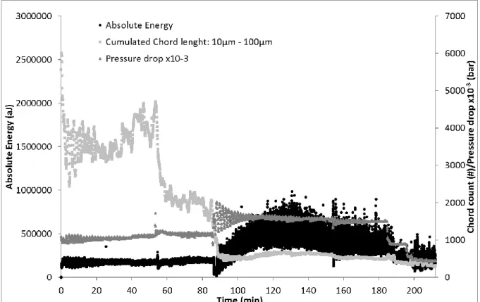
Figure 3 - Energy, chord length and pressure drop during time for experiment at 80 % water cut with Kerdane and 0.005% AA-LDHI at 200 L.h-1.
6
Figure 4 - Energy, chord length and pressure drop during time for experiment at 80 % water cut with Kerdane and 0.005% AA-LDHI at 400 L.h-1.
The dispersions at high water cut are complex and inhomogeneous rather than those at low water cut (Melchuna et al., 2016).
Before the formation of hydrates, experiments show a regular oscillation in the absolute energy (Fig. 1, 2, 3 and 4) characteristic of the state of the dispersion of the droplets in the continuous phase, corresponding to a polydispersed population of droplets around 10 µm. At high water cut (Fig. 3 and 4) the signature of the emulsion is clearly different from that at low water cut (Fig.1 and 2), with significant fluctuations that decrease until a constant value before the crystallization beginning. The fluctuations translate the higher polydispersity of the dispersion, where big droplets of 1 mm are mixed with droplets around 10 µm.
Experiments at high water cut and low flow rate (Fig. 3) show higher polydispersity and heterogeneity with higher fluctuations in the pressure drop and absolute energy, traducing the inability of shear to homogenization.
From the analysis of the cumulated chord length measurements (Melchuna, 2016) at low water cut and 200 L.h-1 the liquid-liquid dispersion is oil continuous, rather than water continuous for
the other three experiments.
When methane was injected, the absolute energy increased and returned to the initial level before the beginning of crystallization. The high transfer of gas into the oil phase seems to affect the attenuation of the signal in case of oil continuous phase. The time between the increase and return to initial level was higher (about 10 min) in oil continuous phase (Fig. 1) than in water (Fig. 2, 3 and 4) where the peak lasted 1 min.
At high water cut and water continuous liquid-liquid dispersion the absolute energy behavior is more chaotic according to the state of dispersion. A peak is detected when methane is injected in the loop, followed by a constant absolute energy with little oscillations at higher or lesser
7
energy than the initial level. The injection of methane seems to affect the structure of the dispersion by coalescence mechanisms, which are corroborated by a decrease in the measured cumulated chord length. This explains why the energy level does not return to the level observed before injection.
The acoustic emission probe detected the crystallization beginning by a steep increase. Even if some oscillations are observed, the tendency of the results is to increase and remain approximately constant until the end of the experiment. The experiment finishes either by stop of the flow due to higher viscosity or plug, or by the rheological study of the slurry transported. The absolute energy seems mainly correlated with the amount of hydrates and the size of the particles/agglomerates, and lesser but still correlated with the continuous phase.
In cases of experiments with plugging and high amount of hydrates (Fig. 1) the increases on pressure drop, chord length and absolute energy are almost proportional. The acoustic emission probe detects the conversion of water droplets into hydrates and agglomerates and their subsequent collision by shear with increasing energy peaks. These ones are proportional to the increasing size of the hydrates and/or agglomerates colliding between them.
Immediately after the formation of the plug the three probes results tend to zero (Fig. 1). In cases of experiments without plugging and with low amount of hydrates (Fig. 2, 3 and 4), the energy increases after the beginning of crystallization. The crystallization of droplets is accompanied by agglomeration and increasing size of droplets into doublets and bigger agglomerates, which increase the energy. Because of the high shear, the maximal size of agglomerates is attained and maintained until the end of the experiment with constant absolute energy.
In all experiments when significant amount of hydrates is formed (Fig. 1, 2 and 3) the pressure drop increased.
Experiment in Fig. 4 with few hydrates show few variations on pressure drop and cumulative chord length and more significant in absolute energy.
The absolute energy after crystallization seems to be linked to the amount of oil and the number of particles. With increasing oil fraction, the energy after the formation of the particles increased from 104 to more than 105 and the maximum chord length account corresponded to
8000 (Fig.1) and 500 (Fig. 2, 3 and 4). This validates the use of acoustic emission probes to follow the fraction of hydrates in a pipe. In order to calibrate the probe two variables must be taken into account: the number of particles/agglomerates and the continuous phase where sound/energy will be transmitted.
During the rheological study with decreasing flow rate (300, 200, 100 L.h-1) (Fig. 2) the chord
length decreases very slightly together with the pressure drop and the absolute energy. The acoustic emission as expected decreases due to the decrease in number of collisions at lower shear. The state of the dispersion is maintained with varying flow rate. These evidences validate the hypothesis to use the acoustic emission to describe the flow pattern.
The rheological study with increasing flow rate (100, 200, 350, 450 L.h-1) show four regions
(Fig. 3) on the absolute energy: first, a very oscillating zone at low flow rate followed by three peaks each one accompanied by one plateau in the pressure drop. The first region corresponds to a non-homogenized suspension with an increase in the chord length and fluctuations in the energy and pressure drop. The other flow rate shows a sharp peak on the energy followed by a plateau at the energy before the rheological study because shear is able to transport the suspension. The cumulated chord length increase at 100 and 200 L.h-1 together
8
with the pressure drop that has the same level than before the rheological study at 200 L.h-1.
The chord length increases due to some changes on the state of the dispersion of the two liquid phases. At 350 and 450 L.h-1 the chord length decreases into almost the same number
than before the rheological study and the pressure drop increases due to higher shear than during crystallization.
The acoustic emission detected the gas injection with the appearance of a peak. The results before crystallization show a typical signature of the emulsion in terms of acoustic absolute energy. The beginning of crystallization is detected by the acoustic emission probe and the following height of the energy peaks is proportional to the sizes of the particles and agglomerates colliding. Plugging was also detected by the acoustic emission. A particular link and proportionality exist between the pressure drop and the absolute energy of acoustic emission together with the number of chord length.
The acoustic emission probe proved to be envisaged to measure the hydrates fraction along the flow loop and also to detect changes in the state of the liquid-liquid dispersion together with the solid, during emulsification and crystallization and even plug and rheological study.
4. CONCLUSIONS
In this work we try to use acoustic emission in addition with analytical techniques such as PVM and FBRM to get other information during hydrates formation in flow loop tests. The firsts results show interesting variations of acoustic emission parameters both during emulsification and crystallization. The experimental results enable to follow the emulsification and the acoustic energy during time seems to be a function of the size and number of the droplets. The energy cushion seems higher in water than in oil continuous phase. This might allow determining the continuous phase during emulsification and crystallization.
The beginning of the crystallization is accompanied by a steep decrease of acoustic energy. The follow up of crystallization was possible from the amplitude of the acoustic signal to detect agglomeration and formation of crystals.
Further work must be done to better understand acoustic emission sources in both the emulsion phase and crystallization. For example, we want to relate collisions energy and agglomeration efficiency must be done in order to calculate the agglomeration rate. In order to complete the analysis of the acoustic signal, a complete analysis of the frequency will be made and will determine different acoustic emission sources. Calibration between the acoustic emission and the solids fraction might enable to follow the hydrate crystallization in industrial processes pipelines.
5. ACKNOWLEDGEMENTS
The authors acknowledge the financial support of TOTAL S.A., CSTJF. 6. REFERENCES
Gherras, N., Serris, E., Fevotte, G., 2012. Monitoring Industrial Pharmaceutical Crystallization Processes Using Acoustic Emission in Pure and Impure Media, International Journal of pharmaceutics 439, 1-2, 109-119.
9
Husin, S., Addali, A., Mba, D., 2013. Feasibility study on the use of the Acoustic Emission technology for monitoring flow patterns in two phase flow, Flow Measurement and Instrumentation, 33, 251-256.
Melchuna, A., Cameirão, A., Herri, J.-M., Glénat, P., 2016. Topological modeling of methane hydrate crystallization from low to high water cut emulsion systems, Fluid Phase Equilibria, 413, 158-169.
El-Alej, M.E., Corsar, M., Mba, D., 2014. Monitoring the presence of water and water–sand droplets in a horizontal pipe with Acoustic Emission technology, Applied Acoustics 82, 38–44. SINTEF, 2010. https://www.sintef.no/globalassets/sintef-petroleum/brosjyre/cold_flow.pdf (accessed 10/8/2017).
Sloan, E. D., Koh, C. A., 2007. Clathrate Hydrates of Natural Gases - 3rd edition. CRC Press Inc.
Sloan, E. D., Koh, C. A., Sum, A.K., 2011. Natural Gas Hydrates in Flow Assurance. GPP – Elsevier.
Hu, Y., Qian, X., Huang, X., Gao L., Yan Y., 2014. Online continuous measurement of the size distribution of pneumatically conveyed particles by acoustic emission methods, Flow Measurement and Instrumentation 40, 163-168.