Technology researchers and makes it freely available over the web where possible.
This is an author-deposited version published in:
https://sam.ensam.eu
Handle ID: .
http://hdl.handle.net/10985/9257
To cite this version :
Laurent DROUEN, JeanFrederic CHARPENTIER, Eric SEMAIL, Stéphane CLENET
-Investigations on the performances of the electrical generator of a rim-driven marine current
turbine” - In: International Conference on Ocean Energy, France, 2008-10 - Investigations on the
performances of the electrical generator of a rim-driven marine current turbine” - 2008
Investigations on the performances of the electrical generator of a
rim-driven marine current turbine
L. Drouen, J.F. Charpentier,
IRENav
BP 600
29240 Brest Armées, France.
laurent.drouen@ecole-navale.fr
E. Semail, S. Clenet,
L2EP
USTL, Bâtiment P2,
59655 Villeneuve d’Ascq, France.
eric.semail@lille.ensam.fr
Abstract
In this paper, the electrical generator of a rim-driven horizontal-axis current turbine is modeled in detail. Its main characteristics and performances are evaluated (efficiency, mass, cost, etc). This generator is of permanent magnet direct-driven synchronous type and is connected to a variable speed power electronics drive. It is then compared to a more traditional technology (a pod generator) in terms of mass and cost for a common set of specification. In addition, due to the specific geometry of the machine, the use of low-cost ferrite magnets is investigated in place of NdFeB magnets.
1. INTRODUCTION
Since the late 1990s, several prototypes of horizontal-axis current turbines have been installed and tested throughout the world. Among them, probably one of the most advanced project, the “Seaflow” has been installed in 2003 on the Devon coast of England by MCT Ltd [1]. It consists in a horizontal-axis turbine with 2 blades, has a 11 meter diameter rotor and looks like a wind turbine. The rotor has a speed around 15 rpm and is connected onto the shaft of a speed-increasing 3 stages gearbox which, in turn, drives a 1000 rpm asynchronous generator. It yields a power up to 300kW with favorable conditions (a current speed of about 2.5m/s). This project has proven that electrical power can be extracted from such a turbine. Another project, called E-Tide, has been developed by Hammerfest Strøm (Norway): the 300kW horizontal-axis turbine has a 15-16m diameter rotor connected to a multi-stage gearbox and an electrical generator. The turbine has delivered electricity to the grid for almost four years [2]. The electromechanical conversion technologies of both projects are very similar and are based on the association of an axial flow turbine with an “off the shelf” electrical generator, directly inspired from the wind turbine conversion systems. The connection is made via a gearbox that adapts the speed of the rotor (typically 10 to 20 rpm) to the speed of the electrical machine (generally above 500 rpm). However, those solutions might not be ideal in terms of complexity, failure rate, efficiency, maintenance and cost. As some investors plan to develop some tidal turbines on a large scale [1], it looks relevant to study some innovative solutions that won’t necessarily look like an immersed wind turbine and will be fitted to the ocean tidal energy extraction. For instance, tidal turbines are placed in
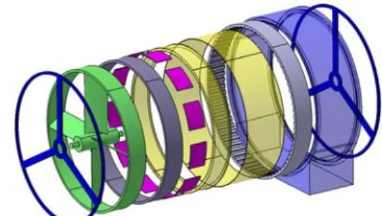
immersed areas of difficult access and it seems critical to minimize the number of maintenance operations. As an example, let’s mention the French prototype “Sabella D03”: the turbine has a 3 meter diameter and a rotation speed of 50 rpm and has been immersed in 2008 in Brittany. This turbine should have a reduced number of failures as its technology is of direct-driven (DD) synchronous type (i.e. without any gearbox, the electrical generator and the rotor having the same rotation speed). Additionally, it must be noted that the gap separating the rotor from the stator is immersed in biodegradable oil. In this paper, a concept of generator adapted to the specific constraints of tidal energy extraction is studied. It consists in a radial magnetic flux electrical machine which surrounds the blades of a horizontal-axis tidal turbine (Fig. 1). The benefits and drawbacks of this structure are highlighted. The paper starts with a general description of the technology. Then, it presents a model that considers electromechanical, thermal and financial aspects and estimates the main characteristics of the electrical generator. A typical set of specification is then defined and the characteristics of the generator are evaluated. Finally, the results are compared with more classical solutions in terms of mass and cost.
Figure 1. . Schematic view of a the studied technology
2. TECHNOLOGY DESCRIPTION
Compared with more conventional solutions, the proposed generator is of direct-driven type. In addition, the active parts of the electrical machine will surround the periphery of the blades (in a classical structure, they are placed on the axis of the turbine) and will be encapsulated into a protective duct.
This concept has already been studied and tested successfully for marine propulsion [3], [4], [5], [6], powers varying from a few hundreds of Watt up to several hundreds of kilowatt. Some of those “rim-driven”
propellers are already commercialized, mainly for bow thrusters or Autonomous Underwater Vehicles propulsion. Vessels propulsion (powers of several MW) has also been studied but it seems that only small scale prototypes have been developed until now. A similar machine, but used now as a generator, has been tested [7] on a small rating turbine (50W) with encouraging results. Actually, some emerging companies have, very recently, manufactured and installed some “rim-driven” generators [8],[9], but very few academic works and experimental results have been published for the time being.
In theory, this structure presents various benefits. First, the gearbox is suppressed. This element is generally made of up to three stages [1] and results in a rather complex, heavy and expensive structure that needs regular lubrication operations. The DD solution, directly derived from wind turbines, leads to less failures and lower maintenance issues [10] which is particularly important in a context of marine current extraction. Secondly, we place the DD, high rated torque and low speed generator around the blades. It is quite advantageous compared with more classical DD machines that are usually heavier and less efficient than higher speed generators [11]. Finally, by housing the generator within a protective duct, it is well know that the hydrodynamic efficiency of the blades is improved. In addition, ducts improve vibration and cavitations performances, as well as protection of blades [6]. It must be noted that ducted turbines are rarely used for wind applications. It can be explained by the fact that, for a given power, a wind turbine is significantly larger than a tidal turbine. Indeed, the power density (W/m2) available from a stream is directly proportional to the fluid density and the cube of the current velocity. Thus, if we compare the power densities of a 2.5m/s water stream and a 13m/s air stream, which are typical velocities, then the power available per square meter is approximately 6 times higher for a tidal turbine (water is nearly 1000 times denser than air). Visual impact, increased cost or mechanical complexity of such structures would probably become unacceptable.
As said above, it is advantageous to put the active part of the generator around the blades as the gap diameter of the machine is increased, which results in a higher torque. Indeed, if we consider a turbine generating a power P with a rotor speed Ω, the torque T of the machine is deduced as follow
1 .Ω− = P
T (1) The electromagnetic (EM) interaction between rotor and stator occurs within the gap that separates them. Considering a classical value of tangential force density σt (N/m2) in the gap, which depends mainly on the machine technology and cooling principle, the EM torque can be expressed as follow
2 / . . DS
T =
σ
t (2) with D, the gap diameter and S the air gap surface area. We understand now that, for a given performance (power and speed), based on (1) and (2), it will be convenient toincrease the gap diameter D as it will decrease the required surface area S, hence the size of the machine. In terms of volume and mass of active components, if we suppose the thickness h independent of the diameter D (this first order assumption is realistic for a given rotation speed), we understand that, for a given torque, the required active volume (approximately the area S time the thickness h) shall decrease with D.
The generator is a synchronous permanent magnet (PM) radial flux machine. Compared with wounded rotors, the use of magnets suppresses the copper losses within the rotor and the efficiency is improved. Additionally, the risk of failures and the maintenance cost tend to be reduced. Induction machines have not been considered. Indeed, with such dimensions (the propeller diameter is several meters long), the gap height wouldn’t be compatible with the principle of induction machines that require very thin separations between rotor and stator in order to limit magnetizing currents and magnetic leakages. The synchronous machine will be associated with an AC/DC Pulse Width Modulation (PWM) voltage converter that can control the current wave into the stator of the generator and, consequently, the rotation speed. An equivalent DC/AC converter (i.e. same structure and rating) is used for the connection to the electrical grid (or directly to a load in the case of an isolated application). This study is a challenge as it has to take into account different disciplines such as electromagnetism, mechanics, hydrodynamics and thermal transfers. For instance, the choice of the minimum gap height, that ensures the separation between stator and rotor, must take into account various constraints. First the magnetic interaction between stator and rotor, secondly the fabrication tolerances, thirdly the distortion and movements of the rotor with respect to the stator due to the action of the very large mass of water flowing through the rotor. On an electromagnetic point of view, a minimum gap is required as, for a given magnet height, the magnets radial flux density at the stator surface decreases with the gap. Another challenge will be the immersion of the gap. As already done for some rim-driven applications [5], [6], we propose to let the water flow through the gap. Thus, it minimizes the sealing problems (classical hub systems need a rotating seal). Moreover, it should improve the thermal performances of the machine. However, since most of the active elements are corrosion sensitive, they will be covered with corrosion-resistant paint or fiber glass plus epoxy coating. Moreover, it is well known that some phenomena like turbulent Taylor vortices may occur between two immersed moving cylinders [12]. The probability of occurrence tends to increase for low clearance ratios (ratio of gap thickness hg to gap radius D/2) which leads to a thicker gap than usual.
3. DESIGN MODEL
3.1. Principle
The design model is used to deduce the performances of the electrical machine for a given set of specification. It is a first order analytical model that permits a fast but fairly precise calculation of the performances of the
machine (efficiency, temperature, mass, etc) and is adapted to an optimization work. It is directly inspired by equivalent analytical models that can be found in [10] and [11] for instance. The input parameters of the model are the machine inner diameter Dint (m), rotational speed Ω (rad/s) and shaft torque Q (N.m) transmitted by the turbine. A certain number of variables are fixed to some relevant values by the designer but they may also vary in a given range if considered as key variables (for a process of optimization).
3.2. Electromechanical model
3.2.1. Equality constraints
The electrical machine is connected to an AC/DC PWM voltage converter that can control the current wave into the stator windings. If the electrical machine current is sinusoidal (with an appropriate control strategy), the medium EM torque is expressed as follow
ψ
π
. . /4).cos .( . . . 2k 1A B1 D2L TEM = w L (3)where kw1 is the winding factor, AL (A/m) is the stator rms electric load, B1 (T) is the peak value of the fundamental of the magnets flux density at the stator surface, D (m) is the gap diameter, L (m) is the iron axial length and ψ is the electrical angle between the stator current and the electromotive force induced by the rotor.
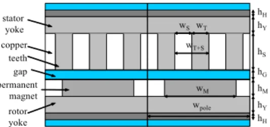
permanent magnet gap hS hY hY hM teeth stator yoke rotor yoke wT wT+S wpole hG wM copper wS hH hH
Figure 2. . Sketch of a cross section of 2 poles of the electrical machine
A linear relationship between the gap height hG and the gap diameter D is proposed
D k
hG = G. (4)
where the coefficient kG takes into account, ideally, magnetic, mechanical, hydrodynamics and thermal considerations.
The relationship between B1, hG, the magnets height hM and the number of pole pairs p, is expressed as follow
) 1 )( 1 ( ) )( 1 ( ) 1 /( 2 ). ) 1 ( 2 1 ( 2 2 2 2 2 2 1 1 1 p sm p rm r p rm p sm r p rm p rm p sm r R R R R p p R p R p R B k B − − − − + − + − + − = − +
μ
μ
β ) 2 / /( 1 M G rm h D h R = − − (5) ) / 2 1 /( 1 h D Rsm= − Gwhere Br is the remanent flux density of the magnets, β is the magnet to pole width ratio and μr is the magnets relative permeability. This formula is of very good accuracy and is derived from a 2D model [14] that solves
the governing field equations by separating the polar variables. It predicts the open-circuit field distribution anywhere in the gap of a slot less surface mounted PM machine. In addition, a coefficient ks, which takes into account the slotting effect, is applied to the gap and magnet heights ) / /( . 1 o e G M r s R h h k = +
μ
+μ
(6) Two formulas are proposed for the reluctance Re in [15]. The first one shall be used in the case of a thin gap )))) 1 ( /( 1 1 .( /( ) . ( G M r1 o t e h h k R = +μ
−μ
− +σ
− (7) ) ) 2 / ( 1 ln( ) / 2 ( ) 2 / ( tan ) / 2 ( 1 ' ' 2 M s s G M s h h w w h w − + =π
−π
σ
where kt is the proportion of teeth, h’M is the magnetic height and ws is the slot width. A second formula shall be used in the case of a thick airgap
) 4 /( )) ln( ) 2 ln( ) 2 (( k k k k D mS p Re= − t − t + t t
μ
o pp (8) where Spp is the number of slots per pole and per phase and m the number of phases. The slots and teeth height hS=hT are linked to the rms electric load AL, the rms current density J(A/m2) in the slot conductors and the slot fill factor kf )) 1 ( . /( f t L S A Jk k h = − (9) The rotor and stator yoke minimum heights hY(min) are chosen such that the flux density into the iron is lower than a maximum value Bmax (that generally corresponds to the saturation limit of the magnetic material). The following formula is determined by considering both superposed effects of magnets (height hYM) and windings (height hYW) on the iron flux density. The flux density in the gap is assumed to be radial.YW YM Y h h h (min)= + (10)
)
4
/(
.
B
1pk
B
maxD
h
YM=
π
β
β)
2
18
/(
.
.
.
' 2 max 2 2D
B
h
p
A
h
YW=
Lμ
oπ
MIt is important to note that the expression of hYW (effect of the windings) is given for the particular case of a three phase regular winding with one slot per pole and per phase (Spp=1). In addition, the relationship between the gap diameter and the rotor inner diameter Dint (m) is reminded G M Y H
h
h
h
h
D
D
=
int+
2
+
2
+
2
+
2
(11) where hH (m) is an additional aluminum thickness that ensures, first, a mechanical integrity to the rotor and, secondly, an interface between the blades and the electrical machine.The iron losses are calculated thanks to classical estimations of global losses pFe (W/kg) per unit mass in
each part of the stator magnetic circuit c Feo Fe b o Fe Fe
p
f
f
B
B
p
o.(
/
)
(
/
)
=
(12) where f (Hz) and BFe (T) are respectively the electrical frequency and flux density in the iron, pFeo (W/kg) is the iron losses per unit mass at a given frequency fo and flux density BFeo, b=1.5 and c=2.2, using typical medium quality Fe-Si laminated steel datasheets. For the calculation of the losses PFe, the flux density amplitude is supposed to be Bmax everywhere in the stator. The relationship between the EM torque TEM and the mechanical torque TMeca is deducedΩ
−
=
Meca Fe/
EM
T
P
T
(13)In this relationship, we assume that the iron losses are mainly caused by the rotation of the rotor. The turbine torque Q being an input data, if the mechanical losses are ignored for this study, then
TMeca=Q (14)
For the special case of a rim driven current turbine, the turbine diameter DT and the rotor internal diameter Dint are the same.
DT=Dint (15)
Moreover, the following geometrical parameters are fixed such that a unique solution to the above equations can be found: p, hM, hG, kt, β, hS, L, kf, hH, hYS and hYR (stator and rotor yoke heights). The winding coefficient kw1 is set to 1 for this study, the electrical angle ψ is set to 0 (to limit the copper losses) and the number of phases is m=3. The current in the conductors is then deduced from
)
2
/(
.
.
A
LD
mpn
sI
=
π
(16)with ns the number of winding turns per phase and per pair of pole. The winding resistance (for each phase) is calculated as follow cond cond
S
L
w
R
=
ρ
/
(17)Scond is the conductor section which can be easily determined by the knowledge of kf, ns and the slot dimensions. Lcond is the total length of a winding conductor, it is composed of two elements: the axial resistance length and the end windings resistance length which can be estimated for each conductor in each end as a wpole diameter half-circle (for Spp=1). ρ (ohm.m) is the conductor resistivity. From equ. (16) and (17), it is then possible to calculate the copper losses
2 ).
.(R R I
m
PCu = a+ ew (18)
as well as the electrical efficiency
)
.
/(
.
Meca Fe Cu Meca elec=
T
Ω
T
Ω
+
P
+
P
η
(19)3.2.2. Inequality constraints
Physical phenomena such as saturation, demagnetization and manufacturing constraints are also considered. If those constraints are correctly defined, the model is a robust tool that eliminates any unrealistic solution. If ψ=0, the effect of the magnets and windings on the teeth saturation can be considered separately. Thus, the teeth saturation by the magnets is not reached as long as
)
/(
max1
k
B
B
k
t≥
β (20)In addition, the teeth saturation by the windings is not reached as long as
)
2
3
/(
.
.
.
.
k
tA
L oD
B
max Mh
'p
≥
μ
π
(21) Again, this relationship is given for the particular case of a three phase regular winding with Spp=1.An additional constraint concerns the tooth shape that must follow the following criterion
max
/
w
R
h
S T≤
(22)where wT is the teeth width and Rmax is a ratio that represents a limit in terms of teeth mechanical integrity. Similarly, the magnets shape is chosen such that the ratio magnet height on magnet width remains realistic
2 max
)
2
/
/(
D
p
R
h
Mβπ
≤
(23)The constraint concerning the demagnetization of the magnets is expressed as follow
cj G o G r L D p B h h H A . . /(3 2 )+ . / )/ ' < (
π
μ
(24)where Hcj (A/m) is the coercive field of the magnets. A thermal model has been built in order to limit the temperatures in the conductors to reasonable values. The constraint on the conductors maximum temperature TCu(max) is simply expressed as follow
max (max) T
TCu ≤ (25) where Tmax is a limit temperature that depends on the conductor class. For a question of clarity, the thermal model is not detailed in this article but can be found in [16]. This model estimates roughly the temperatures in the different parts of the structure thanks to the dimensions and losses evaluated previously. It is based on a simple steady state thermal resistance network directly derived from the heat transfer equations under steady-state conditions.
Additional mechanical constraints are considered. The first one is the thickness of the electrical machine hEM that must be lower than the duct thickness hduct that can be considered as directly proportional to the turbine
diameter DT, i.e. hduct=khduct.DT with khduct<1 T hduct H Y S G M Y H h h h h h h k D h + + + + + + ≤ . (26) Secondly, the total length of the electrical machine Lmach (end windings included) must be lower than the duct length Lduct, considered as directly proportional to the turbine diameter, ie Lduct=kLduct.DT with kLduct<1
T Lduct D k p D L+
π
/ ≤ . (27) Finally, an ultimate constraint concerns the voltage converter electrical frequency that must remain in a realistic range of values(max)
conv conv f
f ≤ (28) The electrical frequency of the converter is directly dependant on the electrical frequency of the machine fmach, i.e. fconv > kfconv1.fmach with
) 2 /(
.p
π
fmach=Ω (29) It also depends on the electrical machine time constant τmach i.e. fconv > kfconv2.1/τmach with
)
/( a ew
mach
mach=L R +R
τ
(30) where Lmach is the machine synchronous inductance (including the slot leakage inductance) that is calculated following classical equations [10],[11].3.3. Validation
The presented EM model has been validated in several typical sets of dimensions with numerical 2D simulations. This validation step is not presented in this paper for conciseness reasons.
3.4. Financial aspects
In order to optimize the design of the machine, the price of the various active parts is evaluated (in Euros per kilogram as seen in table 1), based on typical current values proposed by metal markets. It must be noted that the evaluated cost corresponds only to the cost of the active part of the electrical machine. Structure costs as well as converter and network connection costs were not evaluated. The various isolating resins and the corrosion-resistant paint were ignored.
Table 1: price of the active parts (€/kg)
Copper 6.0 €/kg
Iron 0.5 €/kg
Aluminium 2.0 €/kg
NdFeB 87.0 €/kg
Ferrite 3.5 €/kg
4. RESULTS AND DISCUSSIONS
4.1. RIM generator design
Using the design model presented in the previous section,
we have determined a rough design of a 3 phases rim-driven generator for a set of realistic specification. They correspond to those of the MCT “Seaflow” turbine [1] which is one of the most representative projects at the moment. It is characterized, for its nominal operating point, by the following data: the turbine diameter is DT=11m, the mechanical power is 300kW, the turbine speed is 15rpm and the fluid velocity is 1.5m/s. Table 2 summarizes the parameters fixed into the model.
Table 2: parameters fixed in the model
Rotor inner diameter Dint 11 m Torque transmitted by the turbine Q 191 kN Turbine speed (Ω is in rad.s-1) Ν 15 rpm
Air gap hg 0.02 m
Magnet remanent flux density Br 1.2 T Magnet coercive field Hcj 106 A/m Maximum field in the iron magnetic Bsat 1.4 T Winding coefficient kb1 1 Teeth shape ratio Rmax 5 Electrical angle ψ 0 rad Number of phases m 3
Max. temperature (in the conductors) Tmax 100 °C They are typical design specification of high diameter machines using conventional materials (NdFeB magnets and FeSi laminations). The gap is thicker than in a classical machine because of the mechanical constraints related to very large diameters (the minimum gap height to gap diameter ratio is typically chosen between 0.1 and 0.2%) and also because of the hydrodynamic phenomena that may occur in the gap (see part 2). The windings are very common: one slot per pole and per phase.
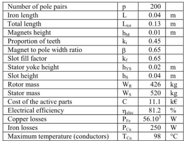
The chosen design objective is the cost minimization of the active parts. The optimum geometry of the machine (number of pole pairs, active length, magnets height, etc) are determined thanks to an adapted optimization process. The main design results (dimensions and cost) are given in table 3. Those results are validated by a 2D FD code which confirms the flux density and EMF levels. It must be noted that an additional constraint has been added: a minimum electrical efficiency of 80%.
Table 3: geometry and performances of the rim-driven solution (optimization of the cost of the active parts) Number of pole pairs p 200 Iron length L 0.04 m Total length Ltot 0.13 m Magnets height hΜ 0.01 m Proportion of teeth kt 0.45 Magnet to pole width ratio β 0.65 Slot fill factor kf 0.65 Stator yoke height hYS 0.02 m
Slot height hS 0.04 m
Rotor mass WR 426 kg
Stator mass WS 520 kg
Cost of the active parts C 11.1 k€ Electrical efficiency ηelec 81.2 % Copper losses PFe 56.103 W
Iron losses PCu 250 W
Maximum temperature (conductors) TCu 98 °C The rotor mass is only 426 kg for a total mass of 946 kg due to a large number of pole pairs (p=200) and also
thanks to the large gap diameter (D=11.2m). This is a good point as the rotating part (rotor and blades) has to be relatively light. The end windings volume in the stator could be reduced by the use of original concentrated fractional slot winding [17], [18] and / or multiphase winding strategies [19]. The structure is particularly thin and short. Thus, a 3D Finite Element EM analysis will be relevant to evaluate the end effects (second order effects only) on such a short machine (4cm of active axial length only). At the same time, those unusual dimensions should favor the integration of the machine into a nozzle with good hydrodynamic performances.
On a thermal point of view, the highest temperature level (in the conductors) should be less than 100°C, which is in accordance with classical electrical machine materials specifications. The thermal study shows that approximately 50% of the heat flux should be evacuated through the gap, confirming the benefits of the water in the gap. The main part of the copper losses is related to the end-windings. The efficiency of the machine (81.2%) can probably be increased by the use of non conventional winding technologies such as concentrated windings that lead to smaller end-windings.
Additional electrical results are summarized in table 4. It shows the influence of the high value of the cyclic reactance (0.78 pu) on the machine performance. This value is typical of direct-drive machines [13] with large gap surfaces. A high reactance implies a low power factor (around 0.74) which leads to an oversized converter (in terms of voltage). In the other hand, it should ensure a good protection of the machine against short-circuits by limiting the currents amplitude. Concerning the electrical time constant τmach, it is high enough (18ms) to limit the required converter switching frequency (a few kHz should be sufficient). For a more accurate calculation of τmach, the reactance of the immersed AC cable (between the machine and the converter) should be included. Estimations show that it tends to reduce the value of the time constant (depending on the cable length) but conclusions should remain the same.
Table 4: additional electrical results
Number of turns par coil ns 6 turns Back EMF (rms) E 200 Vrms
Line current (rms) I 500 Arms Voltage (rms) V 270 Vrms Cyclic reactance Lω 0.78 p.u. Phase resistance R 0.13 p.u. Electrical time constant τ 0.018 s Conductor temperature Tcond 93.7 °C
4.2. Elements of comparison with more classical
machines
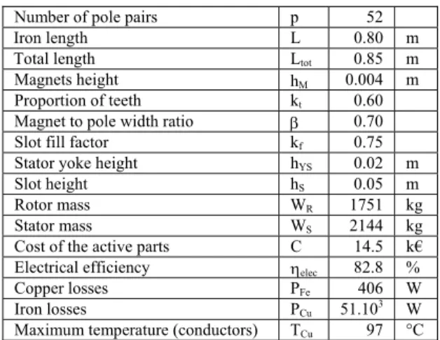
Regarding the mass and cost, the proposed machine seems to be competitive compared with more classical technologies. In terms of comparison, a conventional Direct Driven PM generator driven by the axis with a rotor inner diameter Dint=1.5m is considered (a pod technology). The chosen diameter corresponds to a typical value for this range of power [13]. The same set of specification, but with a lower gap (hg=2.7mm), is considered. The main design results, for an objective of
cost optimization of the active parts, are given in table 5. Table 5: geometry and performances of the pod solution
(optimization of the cost of the active parts) Number of pole pairs p 52 Iron length L 0.80 m Total length Ltot 0.85 m Magnets height hΜ 0.004 m Proportion of teeth kt 0.60 Magnet to pole width ratio β 0.70 Slot fill factor kf 0.75 Stator yoke height hYS 0.02 m
Slot height hS 0.05 m
Rotor mass WR 1751 kg
Stator mass WS 2144 kg Cost of the active parts C 14.5 k€ Electrical efficiency ηelec 82.8 % Copper losses PFe 406 W Iron losses PCu 51.103 W Maximum temperature (conductors) TCu 97 °C The optimized cost of the machine is 14.5k€, i.e. 30% more expensive than for a rim-driven solution. It must be noted that the corresponding active mass (3895kg) is significant, even if our objective was not the mass optimization. Approximate overall dimensions of both machines are represented on Fig. 3 for a visual comparison.
Figure 3. . Comparison of the overall dimensions of both rim-driven and pod electrical machines Now, considering a solution combining a gearbox and a classical “off the shelf” machine with a rotation speed varying between 500 and 1500rpm, the cost of a 300kW three levels gearbox should be close to 20k€ (a medium value varying between 70 and 80 k€/MW is often proposed). Additionally, the active mass of the generator / gearbox association should exceed 4000kg (based on typical values of the wind turbines market).
Both comparisons confirm that the structure should be highly competitive in terms of cost and active mass compared with classical direct driven or geared solutions.
5. USE OF LOW COST MAGNETS
In most cases, Rare-earth magnets (NdFeB or SmCo) are very popular as their high remanent flux densities (up to 1.4T) lead to compact machines. However, those magnets are particularly expensive and tend to represent a large proportion of the price of the active part of the machine. For instance, the NdFeB magnets of the machine studied in part 4 represent approximately more than 50% of the total price (active part only).
Low energy magnets such as Ferrites are much cheaper but, in the mean time, have a lower remanent flux
density. The best values proposed by manufacturers are below 0.45T (using Strontium Ferrites), i.e. approximately three times lower than NdFeB or SmCo magnets values. Thus, based on equation (3), they tend to increase significantly the active length of the machine if the stator current loading AL is supposed the same. However, the results of part 4 reveal that, for that particular application, the active part of the machine is very short and can be increased. Thus, it looks relevant to study a rotor made up of Ferrite magnets.
Based on the same model as previously, we estimated the characteristics of an equivalent rim-driven generator with now Ferrite instead of NdFeB magnets mounted on the surface of the rotor. The design specification remain the same, except the magnet remanent flux density (Br=0.4T) that is supposed three times lower, and the coercive field Hcj=260kA/m. The chosen design objective remains the cost minimization and the design results are given in table 6.
Table 6: geometry and performances of the rim-driven solution using Ferrite magnets
Number of pole pairs p 182 Iron length L 0.12 m Total length Ltot 0.22 m Magnets height hΜ 0.025 m Proportion of teeth kt 0.45 Magnet to pole width ratio β 0.65 Slot fill factor kf 0.60 Stator yoke height hYS 0.02 m
Slot height hS 0.03 m
Rotor mass WR 1350 kg
Stator mass WS 1430 kg Cost of the active parts C 8.4 k€ Electrical efficiency ηelec 81.7 % Copper losses PFe 54.103 W
Iron losses PCu 142 W
Maximum temperature (conductors) TCu 78 °C The machine is still very short as the estimated overall length is 0.22m only. The estimated active mass of the rotor is about 1350kg, which tends to be slightly too much and a multi-criterion cost/mass optimization would be relevant. Ferrite magnets have a lower density (approximately 4900kg/m3 compared with 7500kg/m3 for NdFeB magnets) but the required iron length L is about three times higher than with NdFeB magnets. Regarding the cost of the active part, the simulations reveal that the optimised cost is improved (8.4k€) compared with the NdFeB machine studied in part 4 (i.e. 25% cheaper). The coercive field of the Ferrite magnets (about 260kA/m for anisotropic Ferrite magnets with high remanent flux density) is lower than for NdFeB magnets (about 4 times lower) and the risks of demagnetisation due to abnormal currents in the stator (high transient currents for instance) are increased. It represents one of the main drawbacks of this technology. Thus, the magnets height and number of poles have to be carefully chosen. For the chosen winding configuration and a given current loading, a high number of poles is recommended as it tends to reduce the flux density induced by the stator currents, thus the demagnetisation risks.
The above results tend to prove that Ferrite magnets mounted on the rotor should represent a very attractive solution in terms of dimensions, mass and costs. This approach is particularly original as high rating PM synchronous machines are, most of the time, designed with high energy NdFeB or SmCo magnets that are particularly expensive.
6. CONCLUSION
In this study, an innovative concept of tidal current turbine electrical generator is presented. Based on the integration of a direct-driven permanent magnet synchronous machine in the nozzle of a ducted turbine, it appears to be particularly fitted to the marine current extraction context. This structure has non conventional dimensions and an appropriate model is developed and validated. The main physical characteristics of the active part as well as its cost are roughly estimated. Results are encouraging as, on an electromechanical point of view, this permanent magnet and gearless technology, leading theoretically to less failures and maintenance, is feasible and competitive in terms of cost, mass and volume compared with more conventional technologies. Additionally, simulations reveal that this particular structure should permit the use of low cost permanent magnets which should reduce even more the cost of the active part.
7. REFERENCES
[1] Seaflow, Pilot project for the exploitation of marine currents, European commission community research, 2005, EUR 21616.
[2] http://www.hammerfeststrom.com/ (last accessed Sept. 2008).
[3] L., Matuszewski, K. Falkowski, “Ring thruster with magnetic bearings” in Proceedings of the
IEEE-Ocean 2003 Conference, vol.4, pp 2023-2031.
[4] S.M. Abu-Sharkh, S.H. Lai, S.R. Turnock “Structurally integrated brushless PM motor for miniature propeller thrusters” in the IEE Proc. of
Electr. Power Appl., Sept. 2004, Vol. 151, N° 5, pp.
513-519.
[5] Ø. Krøvel, R. Nilssen, S.E. Skaar, E. Løvli, N. Sandoy, “Design of an integrated 100kW Permanent Magnet Synchronous Machine in a Prototype Thruster for Ship Propulsion” in CD Rom Proceedings of ICEM'2004, Cracow, Poland, Sept. 2004, pp.117-118.
[6] M. Lea et al., “Scale model testing of a commercial rim-driven propulsor pod” in J. of Ship Prod., May 2003, Vol. 19, N°2, pp.121-130.
[7] SM Abu Sharkh, D Morris, SR Turnock, L Myers and AS Bahaj, “Performance of an integrated water turbine PM generator” in IEE conference
publication, 2002, Vol. 487, pp 486-491.
[8] http://www.openhydro.com/ (last accessed Sept. 2008).
[9] http://www.cleancurrent.com/ (last accessed Sept. 2008).
[10] H. Polinder, F.F.A. van der Pijl, G.J. de Vilder, P. Tavner, “Comparison of direct-drive and geared generator concepts for wind turbines”, in IEEE
Trans. on Energy Conv., Sept. 2006, Vol. 21, N°3,
pp. 725-733.
[11] A. Grauers, “Design of direct-driven permanent-magnet generators for wind turbines” Ph.D. dissertation, Chalmers University of Technology, Göteburg, Sweden, 1996.
[12] A.A. Townsend, “Axisymmetric Couette flow at large Taylor numbers” in Journal of Fluid
Mechanics, 1984, Vol. 144, pp. 329-362.
[13] A. Grauers, P. Kasinathan, “Force density limits in low-speed permanent magnet machines due to temperature and reactance,” in IEEE Trans. on
Energy Conv., Sept. 2004, Vol. 19, N° 3, pp.
518-525.
[14] Z.Q. Zhu, D. Howe, E. Bolte, B. Ackermann, “Instantaneous magnetic field distribution in brushless permanent magnet dc motors, Parts I to IV” in IEEE Trans. on Magnetics, Jan. 1993, Vol.29, N°1, pp. 124-158.
[15] E. Matagne, « Contribution à la modélisation des dispositifs électrotechniques en vue de leur
modélisation», Thèse de Doctorat Université catholique de Louvain, 1991.
[16] L. Drouen, J.F. Charpentier, E. Semail, S. Clenet, “Study of an innovative electrical machine fitted to marine current turbines”, in conference proceedings
of IEEE OCEAN’ 07, Aberdeen, Scotland, 18-21
June 2007.
[17] F. Magnusen, D. Svechkarenko, P. Thelin, C. Sadarangani, “Analysis of a PM machine with concentrated fractional pitch windings” in NORPIE
2004 proceedings, Trondheim, Norway, 14-16 June
2004, 8pp.
[18] J. Cros, P. Viarouge, “Synthesis of high performance PM motors with concentrated windings”, in IEEE trans. on energy conv., Vol 17, N°2, June 2002, pp 248-253.
[19] F. Scuiller, J.F. Charpentier, E. Semail, S. Clénet, “A global design strategy for multiphase machine applied to the design of a 7-phase fractional slot concentrated winding PM machine”, in ICEM2006, Chania, Creete Island, 2-5 Sept 2006.