Science Arts & Métiers (SAM)
is an open access repository that collects the work of Arts et Métiers Institute of Technology researchers and makes it freely available over the web where possible.
This is an author-deposited version published in: https://sam.ensam.eu Handle ID: .http://hdl.handle.net/10985/10995
To cite this version :
Raphaël PESCI, Karim INAL, Renaud MASSON - A crystallographic approach of brittle fracture in the 16MND5 bainitic steel. In-situ X-ray diffraction and scanning electron microscope
measurements at low temperatures - 2006
Any correspondence concerning this service should be sent to the repository Administrator : archiveouverte@ensam.eu
A CRYSTALLOGRAPHIC APPROACH OF BRITTLE FRACTURE IN THE 16MND5 BAINITIC STEEL. IN-SITU X-RAY DIFFRACTION AND SCANNING ELECTRON MICROSCOPE MEASUREMENTS
AT LOW TEMPERATURES
R. Pesci1, K. Inal 2 and R. Masson 3
1 LPMM UMR CNRS 7554 - Ecole Nationale Supérieure d’Arts et Métiers - 4 rue Augustin Fresnel - Metz Technopôle - 57078 Metz cedex 3 - France
2 MECASURF - Ecole Nationale Supérieure d’Arts et Métiers - 2 cours des Arts et Métiers - 13617 Aix-en-Provence - France
3 Electricité De France Recherche et Développement - Département Matériaux et Mécanique des Composants - Site des Renardières - Avenue des Renardières - Ecuelles - 77818 Moret-sur-Loing - France
raphael.pesci@metz.ensam.fr, karim.inal@ensam.fr,renaud.masson@edf.fr
ABSTRACT: In-situ experiments have permitted to
describe the behavior and the damaging processes of the 16MND5 bainitic steel at low temperatures. X-ray diffraction has been used to determine the stress states in each phase while the tensile tests realized into a scanning electron microscope have shown brittle microcracks initiating from {100} cleavage facets. A polycrystalline modeling with a two-level homogenization has also been developed: it correctly predicts the effects of temperature and includes an experimentally identified cleavage criterion.
Keywords: In-situ tests, brittle fracture, stress analysis,
cleavage criterion, polycrystalline modelling. 1 INTRODUCTION
Neutron irradiation ageing causes a temper embrittlement of low alloy steels [1] which shifts their ductile to brittle transition range to higher temperatures. As a result, to assess pressure vessel steels integrity during a pressurized thermal shock (in case of an accidental loss of coolant for instance), it becomes necessary to consider their brittle behavior. It is thus very important to characterize the mechanical properties of such un-irradiated materials (especially the toughness as well as the mechanisms responsible for brittle fracture (nucleation and propagation of cracks)) at very low temperatures and to define relevant brittle fracture criteria [2], in order to predict their service life.
In-situ tensile tests have been therefore realized between -196°C and -60°C in a Scanning Electron Microscope (SEM), in order to characterize the behavior and the damaging processes (nucleation/crack-growth, but also appearance of slip lines) of the 16MND5 bainitic pressure vessel steel (ferrite and cementite); brittle microcracks in particular have been observed to initiate and to propagate, thereby leading to the global fracture of the material. In addition, X-Ray Diffraction (XRD) has been used to determine the stress states in the material and especially the fracture stress in ferrite, still during loading at low temperatures.
A polycrystalline modeling has also been developed concurrently with in-situ experimental measurements using a two-level homogenization, which is well adapted to the microstructure composed of an aggregate of
perfectly bonded bainitic grains: it takes into account each kind of heterogeneity as well as the phase and grain
interactions.A Mori-Tanaka formulation [3] first enables
to describe the elastoplastic behavior of a bainitic single crystal (modeled as a single crystal ferritic matrix with cementite inclusions), while the transition to polycrystal is then achieved by a self-consistent approach.
This model correctly predicts the behavior of the considered material, reproduces the effects of temperature and also includes an experimentally identified cleavage criterion. A more detailed modeling of the microstructure is finally presented, considering this time both pure ferritic and bainitic grains (with a constant volume fraction in cementite in the whole material).
2 IN-SITU TESTS AT LOW TEMPERATURES 2.1 Presentation of the 16MND5 bainitic steel
The material considered is a 16MND5 bainitic pressure vessel steel (similar to U.S. A508 cl.3) used in pressurized water reactors; its chemical composition is given in table 1.
C S P Mn Si
0,159 0,008 0,005 1,37 0,024 Ni Cr Mo Cu Al 0,70 0,17 0,50 0,06 0,023
Table 1: Chemical composition of the 16MND5 bainitic steel
(weight percentage, iron balance)
It underwent several heat treatments:
- two austenizations at 865°C/895°C during 4h40 followed by water quench,
- a tempering at 630°C/645°C during 7h30, - a stress-relief treatment at 610°C during 8h.
The obtained microstructure is a bainitic one (fig. 1): the former austenitic are composed of a ferritic matrix containing many carbides (the volume fraction of which is about 5%), mainly under the form of cementite precipitates, such as cementite needles or cementite
spheres: their characteristic dimension is of the order of 0,1µm.
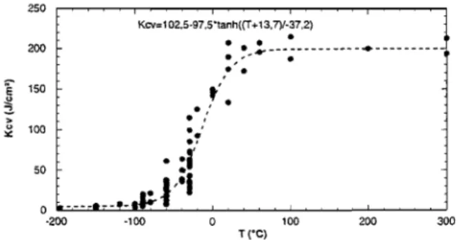
Figure 1: SEM micrograph showing the microstructure of the 16MND5 bainitic steel The resilience curve for this steel has been realized on a wide range of temperatures [-196°C;300°C], as seen in fig. 2 [4].
Figure 2: Resilience curve for the 16MND5 steel [4] It shows a great variety of results in the ductile-to-brittle transition region, which varies from -100°C to 60°C. The present study concerns the low temperatures and the lower part of the transition region [-196°C;-60°C]. 2.2 Brittle fracture characterization
Many in-situ tests have been performed at low temperatures with a small in-situ tensile machine, in order to observe the mechanisms responsible for fracture without unloading. This machine was placed directly inside the SEM (fig. 3), and enabled to characterize the microstructural elements responsible for crack initiation.
Figure 3: In-situ tensile/compressive machine
It was thus possible to follow the evolution of the damaging process during loading. The nucleation of the microcrack responsible for the failure of the specimen
and its propagation were observed, step by step, at -150°C; the concerned area was then located on the
broken specimen, to determine the origin of this microcrack initiation.
The breaking pattern was mixed: although mostly ductile, it also showed a few brittle areas that were uniformly distributed. Our attention was then focused vertically from the crack initiation site, where there was precisely a cleavage facet (fig. 4)!
Figure 4: Cleavage facet on the breaking pattern
(tensile test at -150°C)
This was an important result, because we were able to
clearly identify the site responsible for fracture. We therefore did a Electron Back-Scattered Diffraction
(EBSD) analysis on the breaking pattern of the specimen, in order to determine the crystallographic plane that cleaved, thereby causing the fracture, and to ascertain if it was a {100} plane, as it has already been shown in many studies on ferrite (and more generally in body-centered cubic materials). Several areas were therefore spotted on the facet. These manipulations proved difficult and extremely complicated, because the breaking pattern was not perfectly flat: its important “relief” made it not only difficult to achieve the necessary 70° inclination between the electron beam emitted and the specimen, but also constituted a potential obstacle for the diffracted electrons. In spite of all these difficulties, it was possible to index various Kikuchi line patterns, one of which is presented in fig. 5: the Euler angles (close to orientation 270°, 0°, 0°) and the associated pole figures, enabled us to identify the cleavage plane, to confirm it was a {100} one.
Figure 5: Pole figures corresponding to the Kikuchi line pattern obtained on the cleavage facet analysed
20 µm
2.3 Stress distribution in the material
XRD is perfectly adapted to the study of 16MND5 bainitic steel, because it enables to determine the stress states on various scales, whether it be in each phase
(sin2ψ method) or for several crystallographic
orientations (single crystal analysis method [5]). The small in-situ tensile machine was therefore placed
directly below a SET-X (EDF Renardières research center) or a PROTO (ENSAM of Metz) diffraction goniometer equipped with a linear detector (fig. 6): the stress states in the material could be thus determined
throughout the tensile tests, during loading, at the last point of loading, and after unloading, with the temperature remaining constant all through the proceedings.
Figure 6: In-situ tensile/compressive machine placed below a SET-X diffraction goniometer
Many in-situ tensile tests were thus realized between -196°C and -60°C. At each step of the loading, the stress analyses were realized in ferrite with a linear detector, considering the {211} planes in the tensile direction. The volume fraction of cementite being too small to take some measures, the values of the internal stresses in this phase (I order stresses) were deduced by using the following hypothesis on the macroscopic scale:
I C Fe C Fe I Fe Fe I f f 3 3 . .σ σ σ = + (1)
where fFe and fFe3C respectively represent the volume
fraction of ferrite and cementite, σ is the applied I
macroscopic stress and σ and FeI
I C Fe3
σ are the internal
stress states in each phase of the material.
The stress analyses during loading showed that the stress was higher in cementite, while the stress in ferrite
remained close to that in bainite (σFeI 3C >
I
σ > I
Fe
σ ),
whatever the temperature considered. At -150°C in particular, ferrite did not go beyond 700MPa, while cementite reached values of the order of 2600MPa and seemed to saturate above a certain applied strain value (fig. 7); this phenomenon will be further investigated in part 3 of this paper. The stress difference observed between the average stress in ferrite and the macroscopic one increased with the applied strain,
until it reached 100MPa: it was also higher at low temperatures, never exceeding 150MPa, and could still be more important in other materials such as duplex steels (>200MPa [6]) or pearlitic steels (>400MPa [7]). Besides, the fracture stress in ferrite was close to 700MPa, and seemed to be constant in relation to temperature (-60°C, -80°C, -120°C and -150°C). 0 500 1000 1500 2000 2500 3000 0 1 2 3 4 5 Strain (%) S tre s s (M
Pa) Stress in cementite
Macroscopic stress Stress in ferrite
Figure 7: Stress distribution in the 16MND5 bainitic
steel during an in-situ tensile test at -150°C
3 POLYCRYSTALLINE MODELING
A polycrystalline modeling was also developed using a two-level homogenization, considering the material as
an aggregate of perfectly bonded bainitic grains. A Mori-Tanaka model was first developed to describe
the behavior of a two-phase body centered cubic single
crystal with a matrix/inclusion topology, while a self-consistent model enabled to pass from the crystallographic mechanisms which characterized the grain, to the polycrystalline scale. The elastic behavior of both phases was supposed to be the same, the plastic strain of the matrix being induced by crystallographic gliding when slip systems became active.
3.1 Elastoplastic behavior of the polycrystalline material The Mori-Tanaka model enabled to predict the stress and strain distribution in a two-phase single crystal
composed of a ferritic matrix
( )
Fe with a distribution ofspherical cementite precipitates (Fe3C inclusions which
remain elastic).
The activation of slip systems in ferrite was determined thanks to an energetic criterion, and the elastoplastic
tangent modulus of this phase lijkl was defined by the
relation:
(
)
⎟⎟ ⎠ ⎞ ⎜ ⎜ ⎝ ⎛ + − =∑∑
− g h qrkl h qr gh h op mnop g mn g st ijst ijkl ijkl C C R R C R h R C l . . . . 1. . (2)where lijkl depends on the elastic stiffness tensor Cijkl ,
the orientation tensors Rijg, the set of active slip systems
g and the hardening matrix hgh.
The local behavior law of the bainitic grain was then characterized by: t C Fe Fe t l ε σ& = / 3 .& (3)
(
)
[
]
[
(
)
]
1 / 3 . 3 . . 1 . . − + − − + = l f C T l f I f T lFe FeC Fe FeC Fe isthe two-phase elastoplastic tangent modulus [8] and σ&t
and ε&t are respectively the overall stress and strain of the bainitic grain, considering f the volume fraction
of cementite, CFe3C and lFe the elastic and
elastoplastic characteristics of each phase, and
(
)
[
1]
1 3 . .− − − + = Fe FeC Fe Esh l C l S IT that comes from the
solution of the elastic inclusion problem, with
S
Esh theEshelby tensor.
Finally, a self-consistent model enabled to pass from the crystallographic mechanisms which characterized the grain, to the polycrystalline scale. For elastoplastic heterogeneous materials, the constitutive relation was defined on the macroscopic scale by:
t C Fe Fe C Fe Fe C Fe Fe/ 3 L / 3 .E& / 3 & = Σ (4)
where E&t and Σ& are respectively the macroscopic strain
and stress rates, lFe/Fe3C
( )
Ω are the elastoplastic moduliof the different bainitic single crystals,
Ω
is one grainorientation characterized by Euler angles and the
macroscopic elastoplastic modulus LFe/Fe3C is equal to
( )
[
(
( )
)
]
1 / / 1 / / 3 . . 3 . 3 3 − − Ω − + Ω Esh Fe FeC Fe FeC Fe FeC C Fe Fe I S L l L lIn these conditions, the proposed modeling could predict the per phase average stress distribution in the material during axisymmetric tensile tests. For a tensile test at -60°C for example, one thousand grains were taken into account, the crystallographic orientation of which was chosen at random, plastic gliding was considered on
{ }
110
111
and{ }
211
111
slip systems and theelastic constants were the following: C11=237,4GPa
,
Pa 7 , 134
12 G
C =
and
C44 =116,4GPa.
Besides, onlyg c
τ and the hardening parameters needed to be identified
with experiments: τcg =275MPa, h1 =225MPa and
MPa h h2 =1,2 1=270 . 0 200 400 600 800 1000 1200 0 1 2 3 4 5 6 Strain (%) St ress (MP a ) Model: cementite Model: bainite Model: ferrite Tensile test at -60°C
Figure 8: Stress-strain curve during a tensile test at -60°C on the 16MND5 steel
The resulting stress was higher in cementite while the stress in ferrite remained close to that in bainite
(even after unloading: fig. 8). Cementite also seemed to saturate above a certain strain rate; this result may be surprising at first, but the evolution of stress in cementite in relation to strain in cementite (and not to the macroscopic strain anymore (fig. 9)) confirmed that this phase does remain perfectly elastic.
0 200 400 600 800 1000 1200 0 0,1 0,2 0,3 0,4 0,5 0,6 Strain in cementite (%) S tres s in ce me nt ite (M P a )
Figure 9: Stress in cementite as a function of strain in cementite (tensile test at -60°C on the 16MND5 steel) 3.2 Effects of temperature: comparison model/experiments
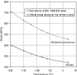
The effects of temperature could be introduced into the model by identifying only the initial value of the critical
resolved shear stress τ parameter for each temperature cg
(fig. 10); indeed, the hardening parameters did not vary, since the tensile tests realized at different temperatures showed that the slopes of the macroscopic stress-strain curves were similar in the elastic and the plastic parts. The predicted yield stress of the material was reported on the same figure, which showed that their evolution was not linear. As expected, the initial value of the critical resolved shear stress was higher at low temperatures since the yield stress and the stress states in the material were then more important. In agreement with the tensile tests performed at temperatures between -196°C and -60°C, it decreased afterwards as temperature increased and tended to a horizontal
asymptote (τ =200MPa), like the yield stress. cg
Figure 10: Evolution with temperature of the yield stress and the initial value of the critical resolved shear stress
Therefore, the model could predict the evolution with temperature of the per phase average stress distribution. The difference between the macroscopic stress and the average stress in ferrite increased with the applied strain and also with decreasing temperatures (fig. 11).
0 100 200 300 400 500 600 700 800 900 0 1 2 3 4 Strain (%) St re ss ( M P a ) Tensile test XRD measurements in ferrite Model: macroscopic stress (bainite) Model: stress in ferrite
Figure 11: Stress-strain curve during a tensile test at -150°C on the 16MND5 steel
These numerical results were consistent with the experimentally observed one (XRD measurements). However, the difference between bainite and ferrite remained underestimated by the model (almost 100MPa).
4 Cleavage fracture criterion
The model enabled to determine as well the stress states in the material for any grain orientation. Since EBSD had shown that cleavage (brittle fracture) occurred normally to the {100} planes in ferrite during tensile tests at low temperatures (see part 2), it was able to
predict in particular the evolution of the σ{ }g100 stress
(stress normal to the {100} planes) in each bainitic single crystal, whatever be its orientation characterized
by the three Euler angles. In this case, σ{ }g100 was
defined by the following relation:
{ }=
∑
j i j ij i g n n , 100 .σ . σ (5)where
n
is the normal to {100} planes.Thus, a damaging criterion was introduced in the model. [9] had already experimentally identified a threshold for
cleavage propagation σcg{ } 465MPa100 = (it remained the
same whatever the orientation of the grain considered),
which corresponded to a critical value of the σ{ }g100
stress in the ferritic grain of duplex steels. Some grains would attain it before others, depending on their crystallographic orientation: therefore, failure would be supposed to take place when a sufficient number of them reached this value (this number, which was identified as equal to 7% of all the grains so that the model was in agreement with the experimental results, was constant with temperature).
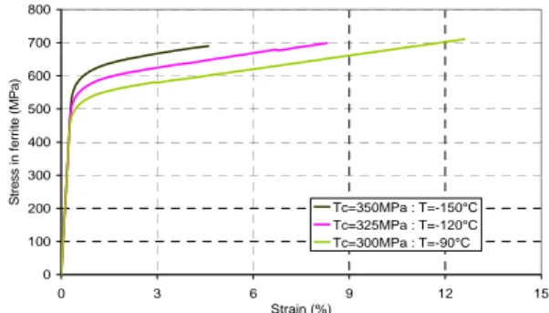
When considering this criterion, the model here presented showed that this failure criterion was reached sooner at low temperatures (fig. 12).
0 100 200 300 400 500 600 700 800 0 3 6 9 12 15 Strain (%) S tre ss i n f e rr it e ( M P a ) Tc=350MPa : T=-150°C Tc=325MPa : T=-120°C Tc=300MPa : T=-90°C
Figure 12: Influence of temperature on the material failure (7% grains reached the cleavage criterion) The stress states and the stress difference between each phase were thus less important (fig. 13): this was explained by the increasing of yield stress (controlled by the critical shear stress) when temperature decreased (almost 100MPa between -150°C and -90°C).
600 800 1000 1200 1400 1600 1800 -160 -140 -120 -100 -80 -60 Temperature (°C) Fr a c tu re st re ss (M P a ) Cementite Bainite Ferrite
Figure 13: Influence of temperature on the fracture stress Besides, the fracture stress in ferrite remained constant in relation to temperature (-90°C, -120°C and -150°C),
which was not the case in bainite and cementite: it strongly depended on the scale considered, its value
being 465MPa on the scale of the crystal (σc 100g{ }) and
685MPa on the macroscopic one. This critical stress was very interesting, since XRD measurements showed
(for example at -150°C: fig. 7) that it remained indeed close to 700MPa! Therefore, the model was coherent since the failure criterion was identified in ferrite: it wouldn’t have been relevant (nor correct) to take it in
bainite, because the stress in this phase was not constant, but increased with temperature, and it was in the ferritic phase that the cracks leading to the global failure of the material had been observed to germinate!
However, the percentage of grains (7%) reaching the failure criterion may seem high; it is possible to adjust it, by considering the material as a polycrystalline aggregate of not only just bainitic grains but both pure ferritic and bainitic grains (15% of the latter presenting a higher local cementite volume fraction of 33%), the volume fraction of cementite remaining constant in the whole material (5%). The first simulations realized have already given a higher stress difference (20MPa
more: fig. 14) between ferrite and the macroscopic value, therefore much closer to the XRD results. As a consequence, the fracture stress in ferrite must have been also modified; indeed, part of the ferrite contained more cementite (it was therefore more stressed), so that the fracture criterion must have been reached sooner. But this remains to be investigated.
0 500 1000 1500 2000 2500 0 5 10 15 20 25 Strain (%) Stress ( M Pa) 15% of the grains containing 33% of cementite Each grain containing 5% of cementite
Figure 14: Comparison between two simulations during a tensile test at -60°C on the 16MND5 steel This more detailed representation of the microstructure proved more precise, all the more so as EBSD measurements had shown that each grain of the material was in fact composed of several packets with their own crystallographic orientation. These packets, which could be furthermore purely ferritic or reinforced with cementite particles (bainitic packets), defined the real characteristic microstructural length of the material and should probably be considered as the “effective grains” in the model.
4 Conclusions
A series of in-situ tensile tests was performed at various low temperatures to characterize the mechanical properties and the fracture processes of the 16MND5 steel: the damage was observed with a SEM and the internal stresses in the ferritic phase were determined by XRD. All these measurements supplied a polycrystalline model with data on a crystallographic scale, which can take into account the effects of temperature by identifying a critical shear stress for each one. It is already efficient since it enables to predict correctly the elastoplastic behavior and the damaging processes of this bainitic steel in relation to temperature.
However, this model will be yet improved. Which percentage of pure ferritic and bainitic grains must be considered to perfectly represent the microstructure of the 16MND5 steel? More in-situ tensile tests at low temperatures must also confirm the experimental results so far obtained and provide new crystallographic damage criteria (especially cleavage initiation and propagation): in particular, the value of the critical stress
{ } 465MPa100 = g
c
σ and the percentage of grains reaching
the failure criterion still need to be discussed and adapted (is 7% of the grains too much? Shall only one
grain be considered to cleave to induce fracture?), in order to agree exactly with the experimental data (especially the fracture stress at each temperature between -196°C at -60°C).
Acknowledgements
Financial support from EDF Research and Development
Division as well as fruitful discussions with G. Rousselier, partner of this study, are gratefully
acknowledged. References
[1]. C. Bouchet, B. Tanguy, J. Besson and S. Bugat. Prediction of the effects of neutron irradiation on the Charpy ductile to brittle transition curve of an A508 pressure vessel steel. Comput.
Mater. Sci., vol. 42 (2005), pp.
294-300.
[2]. T. Narström and M. Isacsson. Microscopic investigation of cleavage initiation in modified A508B pressure vessel steel.
Mater. Sci. and Engin. A, vol.
271(1999), pp. 224-231.
[3]. T. Mori and K. Tanaka. Average stress in matrix and average energy of materials with misfitting inclusions. Acta
Metall., vol. 21 (1973), pp.
571-574.
[4]. S. Renevey. Approches globale et
locale de la rupture dans le domaine de transition fragile-ductile d’un acier faiblement allié. Thesis (1997).
[5]. V. Hauk. Residual Stress Analysis
by Nondestructive Methods.
Elsevier Science B.V. (1977). [6]. K. Inal, P. Gergaud, M. François
and J.L. Lebrun. X-ray diffraction methodologies of macro and pseudo-macro stress analysis in a textured duplex stainless steel. Scand. J. of
Metal., vol. 8 (1999), pp.
139-150.
[7]. M. Belassel. Etude de la
distribution des contraintes d’ordre I et II par diffraction des rayons X dans un acier perlitique. Thesis (1994).
[8]. Y. Benveniste. A new approach to the application of Mori-Tanaka theory in composite materials.
Mech. of Mat., vol. 6 (1987), pp.
147-157.
[9]. L. M’Cirdi, J.L. Lebrun, K. Inal and G. Barbier. Experimental approach of a crystallographic cleavage criterion in a cast aged duplex stainless steel. Act.
Mater., vol. 49 (2001), pp.