Science Arts & Métiers (SAM)
is an open access repository that collects the work of Arts et Métiers Institute of
Technology researchers and makes it freely available over the web where possible.
This is an author-deposited version published in: https://sam.ensam.eu Handle ID: .http://hdl.handle.net/10985/8769
To cite this version :
Nafissah ODEDELE, Christophe OLMI, Jean-Frederic CHARPENTIER - Power Extraction Strategy of a Robust kW Range Marine Tidal Turbine Based on Permanent Magnet Synchronous Generators and Passive Rectifiers - In: 3rd Renewable Power Generation (RPG) Conference 2014, Italy, 2014-09 - 3rd Renewable Power Generation (RPG) Conference 2014 - 2014
Power Extraction Strategy of a Robust kW Range Marine Tidal
Turbine Based on Permanent Magnet Synchronous Generators
and Passive Rectifiers
N. Odedele
†*, C. Olmi
†, JF Charpentier
††French Naval Academy Research Laboratory (IRENav), Brest France (email jean-frederic.charpentier@ecole-navale.fr), *Arts et Métiers Paris Tech,
Keywords: Marine renewable energy, Permanent magnet
synchronous generator, Marine current turbine, passive rectifier.
Abstract
This paper presents a kW range marine tidal current power generation system consisting of a fixed pitch marine current turbine (MCT) with two permanent magnet synchronous generators in the turbine shaft, two diode rectifiers (each rectifier is associated with a permanent magnet synchronous generator) and aDC source voltage. This system is designed for a kW range robust power supply. The specificity of the proposed system is that the two generators have different numbers of turns in their windings and the two rectifiers are in parallel in the same DC source. It has been demonstrated that the proposed system is able to harness very efficiently the energy of the turbine in the whole tidal cycle. The proposed system is interesting because it does not need complex control system and it allows minimizing converter losses costs due to electronic devices as controlled IGBT PWM converters usually used in conventional power generation systems. The analytical results have been confirmed numerically using PSIM software for two kW range generators with the same magnetic circuit and different winding number of turns.
1 Introduction
The resolution of climate and energy equation has favoured traditional green energies development (hydropower, solar, onshore wind turbine, biomass) and the emergence of new renewable energy sectors like marine energies. In this context, France policy is to include in the energy production, a contribution of 23% of renewable energies from 2020 [1]. The most promising marine energy technologies are offshore wind turbines (laid and floating), tidal current technology, wave energy and ocean thermal energy technologies due to the technically exploitable potential of the corresponding resources. Therefore, both academic and industrial current researches are focused on optimizing the operation and profitability of marine renewable energies (MRE). Our paper is focused on marine tidal current energy. In France, there are several very high potential sites for tidal currents and the first tidal energy park of EDF based at Paimpol-Bréhat is currently in testing period and will be efficient in 2015 [2]. The presented work deals with the electrical part associated with a
MCT. If there is a need for very high power MCT connected to electric grid, there is also a need for small power systems for supplying stand-alone installations near tidal current sites in association with energy storage system as batteries. This kind of system can, for example be very useful for supplying measurement stations, buoys, or security installations. In these contexts, developing efficient and very robust system is obviously a key feature.
The state of art of marine tidal turbines, has been entirely reviewed in [3] .The performance of a MCT depends primarily on the nature of the resource (current speed), then on compromises between the different technologies involved and the extraction strategy. The resource is characterized by the kinetic energy of tidal currents and the disturbances which are related to the depth of the site and to the swell. Special solutions for minimizing the negative effects of these disturbances have been studied by adding some electrical components in [4] and [5].
The specification of the turbine (number of blades, fixed or variable pitch, horizontal axis, vertical axis, geometric specifications ...), the generator (permanent magnet synchronous generator, wound synchronous generator, doubly-fed induction generator, squirrel cage induction generator) and the associated power electronics are fundamental technological choices. The extraction strategy has to take into account the geographic positioning of the system relative to currents. The control according to the harnessing strategy can be done by using the pitch of the turbine or by using the generator electronic drive which allows a speed control. The control degrees of freedom vary in accordance with the technologies involved.
In traditional high power systems, a Maximum Power Point Tracking (MPPT) strategy is associated with a power limitation at high fluid velocities. MPPT can be done by a speed control of the turbine using a controllable converter (IGBT PWM rectifier) and power limitation acting on the pitch and/or converter control.
As an example, a direct drive solution with a permanent magnet synchronous generator (PMSG) and a IGBT PWM back to back converter seems particularly interesting for a MCT compared to the use of an induction generator. This classical solution requires in all cases, the implementation of complex power electronics for controlling the generator torque and speed.
The aim of our work is to follow the maximum power operating point with an automatic and passive method,
without using electrical control devices in a similar way as proposed in [6] for an off-grid wind power system. The advantage of this solution is to eliminate the losses of converter, to reduce costs and improve the system reliability compared to conventional systems. A strategy to achieve the maximum power of a PMSG based on fixed pitch marine turbine system associated with passive rectifiers is studied in our paper. This strategy consists in adapting two generators characteristics in order to extract efficiently the energy. A simple analytical model, which is able to predict the system behaviour, is proposed. This model is validated by numerical simulations using PSIM software. The energy efficiency of this strategy is evaluated and compared to the reference case where a classical MPPT control is used.
2 System analytical and numerical Models
2.1 Single PMSG/diode rectifier system
The first studiedbasicsystem consists of a MCT, a direct drive PMSG and a diode rectifier which supplies a fixed DC voltage source (Fig. 1). This DC voltage source can for example be the capacitive filter of an inverter DC bus which supplies power to anAClocal grid and/or battery in the case of a stand-alone installation.
In this system, the mechanical power Pm and the electric
power Pe have been estimated analytically as function of the
rotor mechanical speed and the system parameters. The mechanical power captured from the kinetic energy of tidal currents by a MCT could be formulated as
= (1)
where ρ is the sea density, is the turbine power coefficient,
R is the turbine radius and is the marine current speed.
Figure 1. Simple marine power generator system.
Cp depends on the turbine blade geometry and its
hydrodynamic behaviors [7]. Its maximum value for marine current turbine (MCT) is estimated to be in the range of 0.35 to 0.5 [8]. An analytical approximation of the Cp curve is
given by equation (2) [9] :
= ∗ − ∗ − ∗ − ∗ + (2)
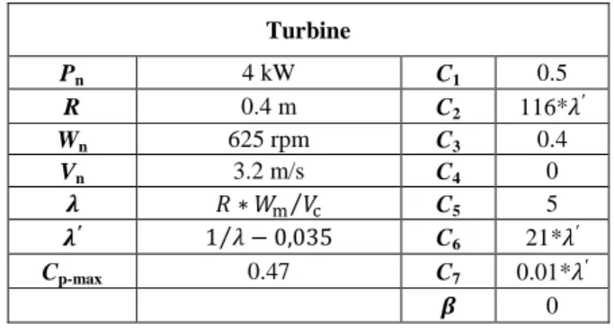
where , , , and β are constant values; and depend on . The values and expressions of the parameters used in the study are given in table 1.
Turbine Pn 4 kW C1 0.5 R 0.4 m C2 116* ′ Wn 625 rpm C3 0.4 Vn 3.2 m/s C4 0 ∗ ⁄ C5 5 ′ 1⁄ − 0,035 C 6 21* ′ Cp-max 0.47 C7 0.01* ′ ' 0
Table1 . Cp Curve Parameters. [7]
It can be noticed that this analytical model of Cp (equation 2)
corresponds to the model which is implemented in the PSIM software [9].
Figure 2. Cp curve of the studied MCT.
Figure 2 shows the power coefficient curve (Cp) obtained with
the parameters of the system summarized in Table 1. This curve allows us to find for each tidal velocity, the curve of the extracted mechanical power VS. the rotating speed of the turbine/PMSG, using equation (1). These curves are given in figure 4 for several values of tidal velocity. In the figure 4, the operating points corresponding to the maximal energy harnessing strategy are given by the intersection of the MPPT curve (red dotted line) and the mechanical power curves. If the operating points of the turbine correspond to the MPPT curve, the turbine will extract the maximum mechanical power for each tidal speed. Therefore, the energy extracted using this MPPT strategy will be used as a reference to estimate the efficiency of our system
The PMSG/rectifier/DC bus system can be represented by the equivalent diagram on figure 3 [12].
Figure 3. Equivalent diagram of the PMSG/rectifier/DC bus system.
In the diagram of figure 3, UD0 represents the offload DC
voltage which is the average value of the diode rectifier output [12], V is the DC bus voltage. It is obtained by the following equation where E is the root mean square (RMS) of the generator back electromotive force (EMF) and k is the flux constant of the PMSG.
()*= √, - , - = / 0 . (3)
RD = 2r represents the Joule losses with r, the phase resistance
of the PMSG [12].
R0 takes into account commutation losses related to diodes
overlap [12]:
)2=,34. (4)
L is the phase cyclic inductance, ω = p.ωm the electrical
pulsation and p, the number of pole pairs. Thus, the DC current can be expressed by:
5) =:6787;:9<= =√
> ?@A 9
B;=>C. .@A. (5)
Hence the expression of electrical power on the DC bus is given in the equation (3):
D= . 5) =
9E=√> ?@A 9F
B;=>C. .@A (6)
Finally, the mechanical power harnessed by the PMSG can be estimated as a function of the speed by equation (7):
= D+ 3G5 + H4 (7)
where I is the RMS phase current 5 = 5) I [12] and H is the frictional coefficient (modelling mechanical losses).
The intersection of the PMSG mechanical power curve VS. rotating speed defined by equation (7) and the turbine mechanical power curves VS. rotating speed, which can be determined using equation (1) and (2) for each tidal velocity (this curves are shown on figure 4), allows to determinate the turbine/PMSG/rectifier system power operating points for a given tidal velocity as shown in Figure 5. The data used to
draw this graph are given in table 1 and table 2. The turbine has been designed to have a maximal tip speed lower than 30 m/s. This tip speed allows avoiding cavitation phenomena in the blades [11].
Figure 4. Mechanical Power curves corresponding to the studied turbine for several tidal velocities.
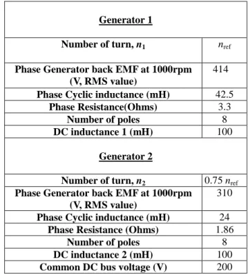
Phase Generator back EMF at 1000rpm (V,
RMS value) 414
Phase Cyclic Inductance (mH) 42.5
Phase Resistance (Ohms) 3.3
Number of Poles 8
DC bus Voltage (V) 200
Frictional Coefficient (N.m.s.rad-1) 0.0179
Table 2. Studied Electric Generator/rectifier Main parameters Thus, if the resource statistic is known (i.e. the number of hours corresponding to each tidal velocity in a studied period), the knowledge of the operating point corresponding to each tidal current velocity will allow us to determine the total amount of energy extracted in this period. Considering the shape of the power curve of the electrical system, it is obvious that a PMSG associated with a rectifier and a constant DC bus is not able to follow an MPPT strategy. That means that even if extracting energy with such a very simple system is possible, this extraction is not really optimal.
Figure 5. Steady state operating point for a MCT/PMSG/Rectifier system.
A way to increase the efficiency of such a system is to control the value of the DC source as in [10] in order to follow the MPPT operating points; but this solution needs, of course, to introduce a controllable converter in the DC bus side.
2.2 Numerical validation of the electrical power model
The system has been simulated with Powersim software (PSIM) in order to validate the proposed simple analytical approach. This software is particularly suitable to simulate such a system because it includes turbines models and power electronics device models.
The analytical (equations 6 and 7) and the numerical (PSIM) results Pe and Pm for different speeds for the PMSG are
shown in figure 7. In this case the PMSG/rectifier system is simulated in PSIM with several constant rotational speeds. The results show a good accordance of analytical and numerical analysis and validate the very simple analytic approach.
Figure 7. Comparison of the analytical and numerical power results.
3 Multi Machine System Performance
3.1 Influence of the number of windings turns.
The electrical power curve delivered by a single generator/rectifier system depends on the generator characteristics (cyclic inductance and electromotive forces) and the fixed DC voltage output (equation 3). For a given magnetic configuration (same magnet and magnetic circuit) and a given value of the DC bus, the electromotive force is directly proportional for a given speed to the number of stator windings turns, which is noted n. In the other hand, the inductance value and the resistance value of the windings are proportional to J . This can be explained because if the global copper section in the slot is considered to be maintained as a constant in rewound process, the conductor section is proportional to 1/n and the total length of the conductor in the winding is proportional to n. It means that if the machine is rewound (and if n varies), the MCT/PMSG/rectifier system performance will be influenced and then, the power generated by the PMSG/rectifier system also.
Figure 8 presents electric power curves (analytical model) for several value of n. In this graph, nref corresponds to the
generator data of table 2.
Figure 8: Electrical power VS speed for several winding number of turns.
3.1 Proposed Multi machine configuration.
It can be noticed considering the shape of the electrical power curves (Fig. 7 and 8) that it is obvious that such a system is not able to extract the power following a MPPT strategy. So let us consider a system composed of a MCT, with two PSMG in the same shaft; each PMSG is associated with a passive rectifier which is connected in the same DC bus (parallel connection of the two rectifiers) (Figure 9).
In this case, for a fixed current speed and a fixed DC voltage, the electrical power characteristics of the global system can be estimated by adding the two subsystems (PMSG/rectifier) electrical power Pe curves. In order to reach the maximum
association of two PMSG with two different numbers of turns in the windings and the same magnetic circuit is considered.
Figure 9. Proposed marine power generator system. This solution can lead to a power curve which fits the theoretical MPPT power curve, if the number of turns of the two machines is well chosen. Accordingly, the chosen configuration associates two PMSG. The main electrical parameters (E, L, R) of the two generators are deduced from the number of winding turns by application of the rules defined in paragraph 3.1. These electrical parameters are summarized in table 3.
Table 2 : Electrical parameters of the two associated generator/rectifiers.
Figure 10 describes the theoretical mechanical and electrical powers VS speed curve of the two machine/rectifier system connected to the DC bus. This curve is estimated by adding the two subsystems (PMSG/rectifier) analytical power Pe and
system curve with the turbine mechanical power curves allows to find the steady state operating points for each tidal speed. It can be noticed that the chosen configuration leads to operating points which are close of the MPPT theoretical curve. So it means that the energy extraction is maximized by this association.
Figure 10: System with 2 machines operating points. Then the total amount of energy in a one year period can be calculated by the knowledge of the resource tidal speed statistics.
Figure 11. Histogram of the absolute values of current speed in the Raz de Sein during one year. (Oi, VS. Vi) [11] The marine resource used in this study is described by statistical data collected in the Raz de Sein during one year. The histogram (Fig. 11) shows for 5 intervals of current speed value centered at Vi= [0.363m/s, 1.090m/s, 1.816m/s,
2.542m/s, 3.268m/s], the corresponding occurrences in hours Oi =[1872h, 3002h, 2427h, 962h, 161h]. The annual current
speed average value is about 1.345 KL . The number of intervals has been deliberately reduced in order to make calculations faster and results presentation more clear. However, the method is of course applicable to finer intervals (and therefore to a larger number of data). [11]
The energy extracted for each current speed is obtained by multiplying the corresponding occurrence (number of hours) by the electrical power delivered at the operating point associated with the current speed. The sum of the extracted energies for each current speed corresponds the total energy
Generator 1
Number of turn, n1 nref
Phase Generator back EMF at 1000rpm (V, RMS value)
414
Phase Cyclic inductance (mH) 42.5
Phase Resistance(Ohms) 3.3
Number of poles 8
DC inductance 1 (mH) 100
Generator 2
Number of turn, n2 0.75 nref
Phase Generator back EMF at 1000rpm (V, RMS value)
310
Phase Cyclic inductance (mH) 24
Phase Resistance (Ohms) 1.86
Number of poles 8
DC inductance 2 (mH) 100
extracted in the year. The annual extracted energy can then be estimated for the combined model of generators and compared to the theoretical perfect MPPT strategy. Of course, this energy amount allows calculating the average power in the period by dividing by the total number of hours.
The system is also simulated for each constant tidal speed by using PSIM software which allows associating turbines, electrical machines and power electronic systems.
Table 3 presents the operating points calculated with analytical models and by numerical simulations and the MPPT theoretical operating point for each considered tidal speed. The analytical and numerical calculations are relatively in good accordance. The two last lines of table 3 present the total amount of energy extracted in the studied period and the corresponding average power. One can notice that around 70% of the MPPT mechanical theoretical amount of energy is extracted by the system. Of course, this electrical energy takes into account mechanical and electrical losses which remain significant for a kW range system (around 20% of mechanical power as shown in figure 10).
Table 3: Harnessed energy and comparison with MPPT optimal strategy.
3
Conclusion
The relevance of a passive power generation strategy based on system composed of a MCT with two direct drive PMSG on its shaft is studied. Each PMSG is associated with a diode rectifier. The two rectifiers are connected in parallel to a DC bus. A simple analytical approach has been proposed to study such a system. This simple model allows to estimate the system performance for a given tidal current resource statistics corresponding to a given site. The analytical results have been confirmed numerically for one and two generators association using multi-physical simulation software (PSIM). These simulations allow validating the model and the proposed concept. It has been demonstrated that such a system can be quite as efficient as a conventional one, based on converters, controlled to follow a maximum power point strategy. The advantage of the proposed system is that the electrical commutation losses are reduced and the system is more robust because of the simplicity and the robustness of the component used.
In the future works, it should be interesting to build an experimental laboratory set up in order to validate the studied
concept. It should also be relevant to take into account the swell disturbance in order to evaluate its influence on the power harnessed by the system.
References
[1] A. Rabain and Y-H. De Reock, “Overview of available resources and the expected outcomes from France, Europe and International projects”, in Proceedings of Marine
Renewable energy Conference, Brest (2013).
[2] L. Terme and N. Gerard, “EDF Paimpol-Bréhat tidal current turbine farm: First achievement and preparation for grid connection”, in Proceedings of Marine Renewable
energy Conference, Brest (2013).
[3] S.E. Ben Elghali, M.E.H. Benbouzid and J.F. Charpentier, “Marine tidal current electric power generation technology: state of the art and current status”, in Proceedings of IEEE IEMDC’07, Antalya (Turkey), 2007, pp. 1407-1412.
[4] Z. Zhou, F. Scuiller, J.F. Charpentier and M.E.H. Benbouzid, “Power smoothing control of a grid-connected marine current turbine system using supercapacitors”, in Proceedings of Marine Renewable energy Conference, Brest (2013).
[5] J.R. Bumby, N. Stannnard, J. Dominy and N. McLeod, “A permanent magnet generator for small scale wind and water turbines”, in Proceedings of the International
Conference on Electrical Machines, Vilamoura (ICEM) 2008,
Paper ID 733, pp. 1-6.
[6] B. Kou, Y. Bai and L. Li, “A novel wind power generator system with automatic maximum power tracking capability”,
IEEE Transactions on Energy Conversion, ,Vol 28, issue 3, 2013, pp 632-642.
[7] Z. Zhou, F. Scuiller, J.F. Charpentier, M.E.H. Benbouzid and T. Tang, “Grid-connected marine current generation system power smoothing control using supercapacitors,”, in Proceedings of the 2012 IEEE IECON, Montreal (Canada), pp.4035-4040, Oct. 2012.
[8] S. Benelghali, R. Balme, K. Le Saux, M.E.H. Benbouzid, J.F. Charpentier and F. Hauville, “A simulation model for the evaluation of the electrical power potential harnessed by a marine current turbine,” IEEE Journal on
Oceanic Engineering, vol. 32, n°4, pp. 786-797, Oct. 2007.
[9] Hua, “PSIM_Manual.book”, (2013).
[10] L. Xie and T. Tang, “Modeling and control of a small marine current power generation system” in proceedings
IEEE International Symposium on Industrial Electronics,
Hangzhou China, (2012), pp. 1438-1442.
[11] L. Drouen, “Machines électriques intégrées à des hélices marines: contribution à une modélisation et conception multi-physique “, PhD Thesis, Arts et Métiers paris Tech (2010) (in french)
[12] G. Seguier, “ Power electronic converters, AC/DC conversion“, Mc Graw Hill Higher Education, (1986), consulted in French version.
Tidal speed Analytical model electrical power Numerical model electrical power (PSIM) Optimal MPPT theoretical mechanical power 0.363 m/s 0 kWh 0 kWh 11 kWh 1.090 m/s 0 kWh 0 kWh 471 kWh 1.816 m/s 1.31 MWh 1.35 MWh 1.77 MWh 2.542 m/s 1.58 MWh 1.59 MWh 1.92 MWh 3.682 m/s 536 MWh 544 kWh 685 kWh Amount of energy 3.43 MWh 3.48 MWh 4.87 MWh