Science Arts & Métiers (SAM)
is an open access repository that collects the work of Arts et Métiers Institute of
Technology researchers and makes it freely available over the web where possible.
This is an author-deposited version published in:
https://sam.ensam.eu
Handle ID: .
http://hdl.handle.net/10985/12694
To cite this version :
Philippe MAYER, Eric BECKER, Régis BIGOT, Bruno KAÏCI - Structural investigation of a new
composite process - In: Proceedings of the 20th International ESAFORM Conference on Material
Forming, Irlande, 2017 - Structural investigation of a new composite process - 2017
Any correspondence concerning this service should be sent to the repository
Administrator :
[email protected]
Structural investigation of a new composite process
Philippe Mayer
1,2, a), Eric Becker
1,b), Régis Bigot
1,c)and Bruno Kaïci
3,d) 1Laboratoire de Conception, Fabrication et Commandes – Arts et Métiers ENSAM - 4, rue Augustin Fresnel -F57078 METZ France.
2Institut de Soudure, 18 av. Général Patton- 57500 Saint-Avold 3 AMVALOR Company - 4, rue Augustin Fresnel - F57078 METZ France.
b)Corresponding author: [email protected]
a)[email protected], c) [email protected], d)[email protected]
Abstract. This work presents a study done on a new patented forming process, created to produce massive composite
parts used for structural applications in automotive and aeronautics industries. The study presented in this paper deals with an experimental setup, used to characterize thick composite cylinders. The author presents the characterization of these cylinders and a new analysis method, in order to understand the consolidation steps of the composite in this forming process. The structural health of the part is illustrated by the analysis of the intra-bundle and inter-bundle porosities, by micrographs characterizations.
Keywords: composite parts shape forming, composite anisotropy, continuous fibers.
INTRODUCTION
Automotive industry creates partnerships with composite manufacturers to find new ways to manufacture tomorrow cars. In this context, the LCFC (Laboratoire de Conception, Fabrication et Commande) and the Institut de Soudure decided to use their knowledge in Forging and composite manufacturing to create a new process for the automotive and aeronautic industries. The objectives are to create structural parts, by forming massive composite preform over the fusion temperature.
Car manufacturers are submitted toregulations in order to reduce CO2 emissions. The objectives for 2020 have already been established by the European community. Different ways are identified to face these new laws, such as the “downsizing” on the motors, or the “lightening” of the cars by reducing the structural parts weight. The latter requires material optimization in order to lighten the structural parts.
Composite parts must be mechanically characterized and their structure must be healthy with minimal voids contents and maximal fibers impregnation. These characterizations must be done in order to improve the contacts between the composite components and create a predictable composite structure. A new composite process is presented in this paper with mechanical characterization of thick cylinder. The objective of this study is to create a testing method for this new composite process.
PROCESS POSITION IN THE COMPOSITE FORMING INDUSTRY
In term of performance, the objective is to place the process near the CFRT (Continuous fiber reinforced thermoplastic), and the winding method. Both of them use continuous fibers at high fiber volume ratio with the purpose of creating highly resistant products.
The process presented in this article was developed in order to answer to the aeronautics industry demands as presented in the introduction. To produce structural, two “sine qua non” conditions are established: parts must be resistant to the structural constraints imposed and they should be produced at high speed in order to be competitive. In term of production rate, the objective is to place the process near the SMC (sheet molding compound) and the BMC (bulk molding compound) methods because they are currently used at high rate productions.
EXPERIMENTAL INVESTIGATIONS
The present study has been decided to characterize the new fabrication process. It has been decided to create thick composite cylinders with commingled yarns in order to test the material used in the process.
Commingled yarn
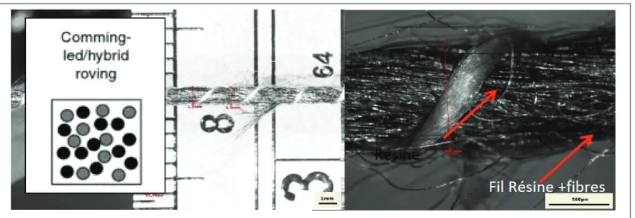
In order to produce the parts a commingled yarn C/PPS provided by Schappe Technic is used. This commingled yarn is presented bellow on figure 1. The yarn is composed by 2 types of fibers:
x The stretched broken carbon fiber (1-8 cm long, black on figure 1) x The PPS fiber in and around the yarn (in white on figure 1)
This yarn has the advantage to be easily placed and consolidated with good mechanical properties (better than short fibers and a little less than continuous fibers). They has been used in consolidation study by (Bernet and Michaud 2001) in order to create consolidation model based on (Klinkmüller et al. 1995) and (Gutowski et al. 1987).
Figure 1 : Commingled yarn morphology
A thermal characterization has been done to know the different temperatures used to do the consolidation of the parts: the fusion is around 285°C for the PPS, so the best consolidation temperature should be around 300-315°C. Mechanical testing of the fibers shows that after 30N of tension there is an elongation of the composite which is not negligible, that is why the entire winding step will be set between 1N of winding tension and 30N. The yarn has a diameter around 0.9 mm. This diameter lightly changes with the tension; that is why the winding program has been adapted in the process.
Fabrication process
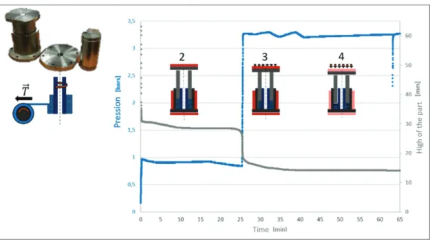
In order to characterize the fabrication process of this study, a simple geometry has been decided; a ring. The production of these kinds of rings is always the same in our case of study: (All the steps are presented on the figure 2 below)
1. Winding the yarn with a constant tension (between 1N and 30N as told before), a specific tool has been designed for a winding with a robot
2. Heating the tools with two heating plates and one heating ring. 3. Start of the compression and consolidation phase.
4. Cooling the tools with or without forced convection
Figure 2 : Fabrication process and steps
After the consolidation and the cooling of the tools to a temperature below the recrystallization, the part is extracted in order to be measured and characterized. The dimensions of the final parts are around 20 mm high with an interior diameter of 50 mm and an exterior diameter of 70 mm. It looks like the cylinder presented on figure 3, which presents a thick composite cylinder produced with commingled yarn.
Figure 3 : Cylinder produced with the process of this study
Mechanical testing
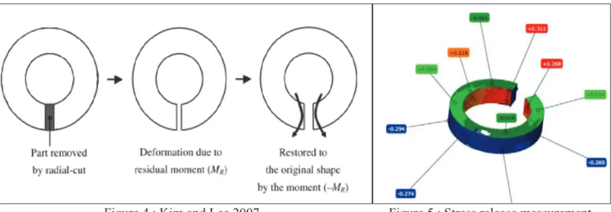
The mechanical testing of the parts has been inspired by (Kim and Lee 2007). The cylinders are cut with a precise saw. After cutting the cylinders the stresses are released and there is a physical expression of this stress; inside and outside diameters change. The stress release is illustrated on figure 5 by comparison of two measurements (before and after cutting the rings):
x The outside diameter decreases about 0.28 mm x The inside diameter decreases about 0.3 mm
Figure 4 : Kim and Lee 2007 Figure 5 : Stress release measurement This stress release can induce some fracture in the middle of the composite. The stress is a process induced phenomenon, depending on the winding tension and on the fabrication parameters like the temperature and the pression during the forming process. One of the first point to verify in the process is to understand quantify the deformation due to residual stresses.
In their tensile test Kim and Lee use strain gauge in order to see the deformation of the parts during the test. They placed the gauges inside and outside the cut ring. I the present case of study, another method have been used speckled pattern to determine the 2D deformation of the ring. This method is easy to set up with a camera and graphite spray. During the mechanical test, the deformation of the front side is analyzed by software which name is GOM Correlate and all the deformations are shown. The user can create numerical gauge in order to see the deformations along one specific axis and create graphics of this deformation depending on the time. The force, which is retrieved by the traction bench, is easily correlate with the analysis. The displacements of the cylinders are retrieved by an extensometer, fixed at the cut ring, as shown on the figure 6 below.
Mechanical results & morphological characterization
All the mechanical phases of the tensile test have been represented on figure 7. x First the internal stress is compensated (Around 0.3 kN)
x The elastic deformation of the ring (1 kN, 1.3 mm displacement) x Delamination and destruction of the structure
x Returning to 0 (0N with a final displacement corresponding to the beginning of delaminating phase)
Figure 7 : Force and displacement during a tensile test
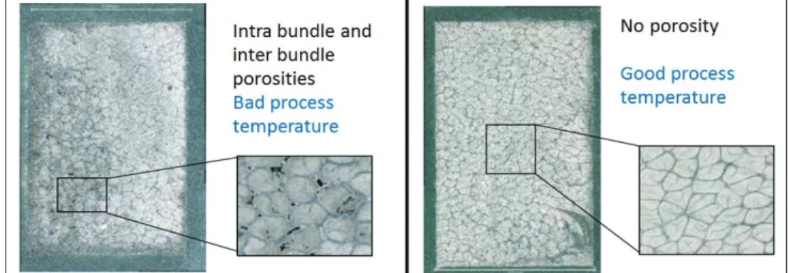
Mechanical tests show the best results with some specific parameter like the initial tension of the fibers and the best process temperature (Fusion temperature +X°C). These results have been correlated with a morphological characterization of the ring, by micrographs and bundle analysis (figure 8).
Figure 8 : Example of two parts created with two different setups
DISCUSSION ABOUT CURRENT WORK
The mechanical behavior of thick cylinder presents complex stresses; more than a tensile test, its looks like a three points flexion with traction inside and compression outside. This reaction depends directly on the composition of the ring (repartition of the fibers in the section, porosities, etc). The mechanical test is fits better as a comparison
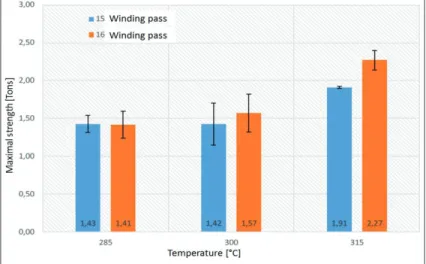
than a quantitative method. Another nice point of view is that, with the GOM Correlate method, the user can predict the delamination of the part before it appears. In an industrial way, this method can improve the comprehension of the stresses in the part during the effort, and predict the destruction of the part (with certain limits). The residual stresses have been quantified in another point of this study. For example the influence of the temperature is presented in the figure 9. The maximal strength is increased by 30% with good thermal setting of the consolidation.
Figure 9 : Influence of the temperature on the maximal strength
CONCLUSIONS & OUTLOOKS
The study presented in this paper is a part of a global processing study, done in order to understand the influence of entry parameters like the consolidation temperature, the tension of the fibers during the winding phase, etc. The aim of the study was to create a testing method in order to understand the mechanical behavior of the parts done with the fabrication process of the global project. To do this, thick cylinders have been produced with different parameters and have been characterized. In a mechanical point of view, the tests have proved that the consolidation temperature impacts directly the material impregnation, and has been. A direct link between the mechanical behavior of the composite and the temperature of consolidation has been verified. The next steps of the study will be to find the best processing parameters with a more accurate experimental plan.
ACKNOWLEDGMENTS
We thank Prof. Artan Sinoimeri of the Haute Alsace University for his support.
REFERENCES
1. Bernet, N, and V Michaud. 2001. “Commingled Yarn Composites for Rapid Processing of Complex Shapes.”
Composites Part A: Applied … 32: 1613–26.
http://www.sciencedirect.com/science/article/pii/S1359835X00001809.
2. Gutowski, T G, Z Cai, S Bauer, D Boucher, J Kingery, and S Wineman. 1987. “Consolidation Experiments for Laminate Composites.” Journal of Composite Materials 21 (7): 650–69.
http://www.scopus.com/inward/record.url?eid=2-s2.0-0023381308&partnerID=40&md5=76780cf9d1e36698b62a62e870c69958.
3. Kim, Jong Woon, and Dai Gil Lee. 2007. “Measurement of Residual Stresses in Thick Composite Cylinders by the Radial-Cut-Cylinder-Bending Method.” Composite Structures 77 (4): 444–56. doi:10.1016/j.compstruct.2005.07.020.
4. Klinkmüller, V, R Kästel, L Ye, and K Friedrich. 1995. “On Impregnation Quality and Resulting Mechanical Properties of Compression Moulded Commingled Yarn Based Thermoplastic Composites,” 189–201.