Science Arts & Métiers (SAM)
is an open access repository that collects the work of Arts et Métiers Institute of
Technology researchers and makes it freely available over the web where possible.
This is an author-deposited version published in: https://sam.ensam.eu Handle ID: .http://hdl.handle.net/10985/10105
To cite this version :
Olivier THOMAS, Fabrice MATHIEU, W. MANSFIELD, C. HUANG, Susan TROLIER MCKINSTRY, Liviu NICU - Piezoelectric amplifiers with integrated actuation and sensing
capabilities - In: 26th. IEEE international conference on micro electro mechanical systems (MEMS 2013), Taiwan, 2013-01 - Proc. of the 26yh. IEEE international conference on micro electro mechanical systems (MEMS 2013) - 2013
Any correspondence concerning this service should be sent to the repository Administrator : [email protected]
PIEZOELECTRIC PARAMETRIC AMPLIFIERS WITH INTEGRATED
ACTUATION AND SENSING CAPABILITIES
O. Thomas
1,*, F. Mathieu
2, W. Mansfield
3, C. Huang
3, S. Trolier-McKinstry
3and L. Nicu
21
Arts et Métiers ParisTech/LSIS, FRANCE
2LAAS-CNRS, FRANCE
3Pennsylvania State University, USA
ABSTRACT
We report in this work on unprecedented levels of parametric amplification in microelectromechanical systems (MEMS) resonators with integrated piezoelectric actuation and sensing capabilities operated in air. The method presented here relies on accurate analytical modeling taking into account the geometrical nonlinearities inherent to the bridge-like configuration of the resonators used. The model provides, for the first time, precise analytical formula of the quality factor (Q) enhancement depending on the resonant mode examined. Experimental validations were conducted for resonant modes exhibiting, respectively, hard and soft-spring effects when driven in the nonlinear regime; Q amplification by a factor up to 14 has been obtained in air.
INTRODUCTION
Micromachined mechanical resonators are the subject of much attention due to their very high natural frequencies, large mechanical quality factors and low power operation. Among the vast field of applications, one can primarily highlight electronic filtering [1] and ultra-sensitive mass sensors [2]. In those applications, one key parameter is the quality factors of the resonances, which is directly related to either the sensor sensitivity or the filter selectivity [3]. When operated in air or in liquid, the quality factor dramatically decreases, thus leading to loss of performance. Several strategies have been proposed to overcome those difficulties, such as active closed loop enhancement [4, 5], or parametric amplification, introduced by the pioneering work of Rugar and Grutter [6] and used for torsional microresonators [7]. More recently, this principle has been applied to nano-beams, driven by Lorentz forces in [8] and by piezoelectric action in [9], and to an array of microcantilevers in [10]. Pure parametric actuation has also been widely considered, for signal filtering [11], mass sensing [12], signal amplification [13] or logic circuitry [14, 15].
In this paper, micromachined resonators with an integrated piezoelectric layer for actuation and detection purposes are described. An enhancement of up to a factor 14 was obtained by parametric amplification, with operation in air. Moreover, the impact of geometrical nonlinearities, which limits the devices performances, was investigated through reduced order modeling and numerical simulations, thus leading to (i) closed form expressions for the Q-factor enhancement and (ii) an efficient design rule to predict and overcome the
nonlinearity threshold.
EXPERIMENTAL METHODS
Fabrication of piezoelectric MEMS
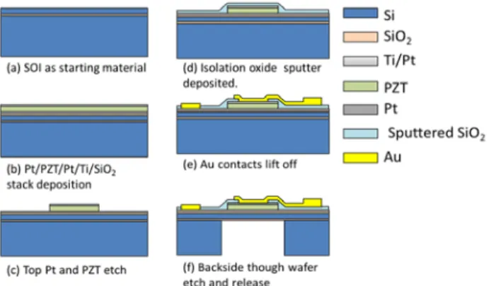
The fabrication process for the piezoelectric MEMS resonators is depicted in Fig. 1. A double-side polished silicon-on-insulator (SOI) wafer with a 2 µm Si device layer and a 1 µm buried oxide layer was used as the starting substrate. The mask set for the wafer hosts chips bearing 50-µm wide bridges and paired, with lengths of 300 µm, 500 µm or 700 µm. The piezoelectric layer covers one eighth of the bridge length at each of the ends.
Figure 1: Fabrication flow-chart for the micro-machined piezoelectric resonators.
To fabricate these devices, the first step was the growth of a 100-nm-thick thermal silicon dioxide film on the SOI wafer. A metal-complex oxide-metal sandwich structure was then deposited on the thermal SiO2. A
bottom electrode consisting of a 20 nm titanium adhesion layer and 100nm platinum of Pt was then deposited. A 1.6 µm layer of lead zirconate titanate (PZT: Pb(Zr0.52Ti0.48)O3) was then spin deposited from a sol gel
solution on the bottom electrode as described elsewhere [16]. Finally, a top electrode of 100nm of platinum was sputter-deposited on the PZT. Subsequent lithography defined the active device structure. The active device pattern was transferred to the top electrode (100nm Pt) and the 1.6 µm PZT layer by dry etching using a thick resist as a mask (Shipley SPR220).
The dry etch process was run in a Tegal 6540 HRe– capacitively coupled plasma chamber using a mixture of Cl2 and CF4 gases and a process pressure of ~ 5 mTorr.
The PZT etch was stopped on the bottom platinum electrode. A second set of lithography and plasma etch
steps were used to define the bottom electrode patterns. A 400-nm-thick isolation film of silicon dioxide was then sputter deposited to avoid possible hydrogen damage of the PZT piezoelectric layer. Contact lithography and inductively coupled plasma (ICP) oxide etch processes were then used to open contacts to both top and bottom electrodes. The interconnect traces and pads were formed by a liftoff process of an electron beam-evaporated Ti/Au (10/150 nm) metal onto an undercut bi-level resist structure. A separate lithography step was then utilized to define the cantilever device structures; the isolation oxide, device silicon and buried oxide was etched using ICP etch processes (in a PlasmaTherm Versalock cluster tool) to form the beam structures. The cantilever and membrane devices were released utilizing backside thick resist lithography and Bosch etching through the handle wafer. The etching was stopped on the SOI buried oxide layer. During this step, the front-side structures were protected with a thick resist layer. After the handle wafer etch, the protection resist was removed to release both cantilever structures and membrane structures and the device chips were gently extracted from the wafer by applying pressure with tweezers at the separating paths running through the wafer.
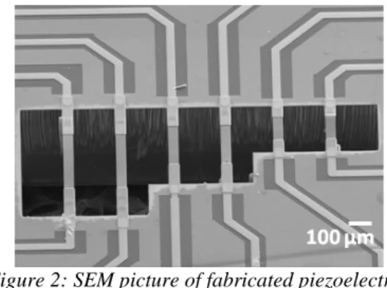
Scanning electron microscope (SEM) image of micromachined bridges is shown in Figure 2.
Figure 2: SEM picture of fabricated piezoelectric microbridges.
THEORETICAL CONSIDERATIONS
When electrically actuated, the piezoelectric layers attempt to contract laterally in proportion to the applied voltage
V
(t
)
. The mechanical action on the beam is equivalent to a concentrated moment and an axial force applied at the end of the piezoelectric layer. As a consequence, the beam is subjected to a bending action as well as a modulation of its axial tension. Since the axial tension modifies the natural frequencies of the beam, parametric driving is achievable. Parametric amplification consists of driving the beam in bending at a frequency Ω and superimposing a parametric “pump” at 2Ω, which is simply realized here witht V t V t V()= dcos(Ω +ϕ)+ pcos2Ω (1)
By choosing the phase difference ϕ, amplification of the resonance peak can be obtained, when Ω is close to a natural frequency of the beam [6, 17].
A model of the microelectromechanical beams that includes the constituent layers, the change in cross-section and the geometrical nonlinearities can be obtained by the finite-element method [18]. If this model is reduced to only one mode of vibration, the corresponding modal coordinate
u
(t
)
obeys: ) cos( 2 cos 3 2 0 0 ω δ ϕ ω + +Γ + Ω = Ω + + u u u u t F t Q u d (2)where Q is the mechanical quality factor of the mode, ω0 is its natural frequency, Fd and δ are the direct and parametric forcing amplitudes, proportional to Vd and V p
respectively and Γ is the geometrical nonlinearity parameter.
The parametric amplification is first considered by means of the model of Eq. (2), without geometrical nonlinearities (Γ=0). It can be shown that at first order,
) cos( )
(t =a Ωt+ψ
u , where ais known from a closed-form expression as a function of Ω , ϕ, Fd,
δ
, ω0 andQ [6, 8, 17]. For a non zero parametric pump (δ ≠0), the curve a as a function of Ω has a resonant shape, which depends on ϕ. With ϕ −= π/4, the system’s response under parametric excitation has a higher amplitude at resonance with a narrower bandwidth, associated with an effective quality factor Qeff =∆ω/ω0 where ∆ω is the -3 dB bandwidth.
The main theoretical result is that the gain at resonance G0 and the quality factor enhancement
Q
Qeff/ are functions of only one dimensionless
parametric driving amplitude δ =δ/δcr:
η δ δ (1 ) 1 , 1 1 0 − = − = Q Q G eff 3)
where η=0.527 and δ =cr 2ω0/Q. The gain relation is
related to the closed-form expression of [6, 9, 18] while the one for Qeff was obtained here by a fit from numerical
results obtained by continuation of periodic solutions [19]. δcr is the critical amplitude of the pure parametric forcing: if the system is driven only by a parametric actuation (Fd = 0 in Eq. (2)), a non-zero response is
obtained only if the driving amplitude δ is above δcr. Experimental examples of purely parametric response are shown on Fig. 3. In contrast, if F ≠0, parametric amplification is obtained with δ below δcr. As δ approachesδcr, the gain and the effective quality factor theoretically tend to infinity, so that any quality factor is potentially attainable by this method.
Practically, the immovable ends of the beam in the axial direction create a nonlinear axial/bending coupling, modeled here by the cubic term of coefficient Γ . Its influence is noticeable for large amplitudes of the response, for which the resonance curve is bent to the low or high frequencies, depending on the sign of Γ . It thus appears that the geometrical nonlinearities impose a limit in response amplitude above which the bending of the resonance curve is noticeable. A theoretical estimation of this limit, based on Eq (2), is proposed in [19]. It shows that the maximum gain and quality factor enhancement achievable without observing the resonance curve bending can be written:
γη γ N Q Q N G eff = = max max , 4)
where γ =2/(2+η)≈0.792 and Nis inversely proportional to Fdand does not depends on δ. As a consequence, the less the direct forcing, the more efficient the parametric forcing will be.
RESULTS AND DISCUSSIONS
Experimental set-up
Piezoelectric materials allow integrated actuation and sensing capabilities. However, this class of materials comes with important capacitive parasitic effects which can hide variations of charges due to the motion. To avoid such effects, we propose a differential actuation and detection scheme by means of a blocked reference structure. The excitation voltage is applied to the measurement structure, and the same inverted signal is applied to the reference. The amplitude tuning allows removing almost all of the capacitive effect at the input of the detection charge amplifier level. A signal synthesizer Tektronix AGF3102 generates up and down frequency sweep of the parametric equation (1) around the resonance frequency. Eventually, the charge amplifier output signal is fed through an Agilent 4395A configured in spectrum analyzer with maximum hold acquisition operation mode.
Measurement of piezoelectric microresonators parametric amplification phenomena
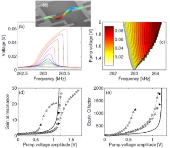
The experimental response of one mode of a 500 μm micro-bridge is shown in Fig. 3.
Figure 3 : Experimental results on a 500 μm microbridge, for a mode of resonance frequency 263.1 kHz and Q = 125. (a) operational deformed shape obtained with a laser vibrometer; (b) resonance curves for various values of the parametric pump; (c) resonance curve in pure parametric driving; (d,e) Gain and quality factor enhancement as a function of the parametric forcing voltage. The solid lines
show the theoretical formula (3) and the markers stems from experiments, for various values of the direct forcing
amplitude. The black markers are associated to the geometrical nonlinearities threshold
The geometrical nonlinearities are clearly noticeable, by a hardening effect that bend the resonance curves toward the high frequencies. Figure 3(b) leads to a critical value of the parametric pump 1.2V. Figures 3(c,d) validate the analytical gain and Qeff/Q formulae (3) in the
linear range, and clearly show the effect of the geometrical nonlinearities: if one increases the parametric forcing, the response amplitude increases until a critical value above which the bending of the resonance curve is noticeable. At this point, the gain and Qeff diverge from
the theoretical formulae (3).
The parametric amplification process is clearly observable in Figs. 3(b), with a Q-factor enhancement up to a factor 14 for the 500 μm beam, in air. As already noticed, following the theoretical formula (3), a given Q-factor enhancement relies only on the choice of Fd, with
no theoretical limitation: the smaller Fd is, the larger the
parametric amplification effect will be. In practice, the voltages Vd and Vp can be separated by several orders of
magnitude (The best Q-factor enhancements were obtained with Vd = 4mV and Vp= 1.15V for the 500 μm
beam), which is the main limitation.
CONCLUSION
In conclusion, the parametric amplification concept has been studied in detail, both theoretically and experimentally. The main result obtained is a set of original formulae that gives a very useful rule to practically adjust the main parameters of a parametric
amplifier: the maximal value of the direct drive and the parametric pump amplitude, for a given targeted Q-factor enhancement. This provides an important design rule to either avoid or exploit the nonlinear dynamics of MEMS in order to enhance their performance.
ACKNOWLEDGEMENTS
The French National Agency for Research (program ANR/PNANO 2008, project NEMSPIEZO ‘‘ANR-08-NANO-015’’) is acknowledged for financial support.
REFERENCES
[1] V. B. Chivukula and J. F. Rhoads, “Microelectromechanical bandpass filters based on cyclic coupling architectures”, J. Sound. Vibr., vol. 329, pp. 4313-4332, 2010.
[2] B. Ilic, Y. Yang, H. G. Craighead, “Virus detection using nanoelectromechanical devices”, Appl. Phys. Lett., vol. 85, pp. 2604-2606, 2004.
[3] K. L. Ekinci, Y. T. Yang, and M. L. Roukes, “Ultimate limits to inertial mass sensing based upon nanoelectromechanical systems”, J. Appl. Phys. vol. 95, pp. 2682-84, 2004.
[4] T. Alava, F. Mathieu, L. Mazenq, C. Soyer, D. Remiens, and L. Nicu, “Silicon-based micromembranes with piezoelectric actuation and piezoresistive detection for sensing purposes in liquid media”, J. Micromech.
Microeng. vol. 20, 075014, 2010.
[5] T. Manzaneque, J. Hernando-Garcıa, A. Ababneh, P. Schwarz, H. Seidel, U. Schmid, and J. L. Sanchez-Rojas, “Qualitu-factor amplification in piezoelectric MEMS resonators applying an all-electrical feedback loop”, J.
Micromech. Microeng. vol. 21, 025007, 2011.
[6] D. Rugar and P. Grutter, “Mechanical parametric amplification and thermomechanical noise squeezing”,
Phys. Rev. Lett. vol. 67, pp. 699-702, 1991.
[7] D. W. Carr, S. Evoy, L. Sekaric, H. G. Craighead, and J. M. Parpia, “Parametric amplification in a torsional microresonator”, Appl. Phys. Lett. vol. 77, pp. 1545-1547, 2000.
[8] R. B. Karabalin, X. L. Feng, and M. L. Roukes, “Parametric amplification at very high frequency”, Nano
Lett. vol. 9, pp. 3116-3123, 2009.
[9] R. B. Karabalin, S. C. Masmanidis, and M. L. Roukes, “Efficient parametric amplification in high and very high frequency piezoelectric nanoelectromechanical systems”,
Appl. Phys. Lett. vol. 97, 183101, 2010.
[10] Z. Yie, N. J. Miller, S. W. Shaw, and K. L. Turner, “Parametric amplification in a resonant sensing array”, J.
Micromech. Microeng. vol. 22, 035004, 2012.
[11] J. F. Rhoads, S. W. Shaw, K. L. Turner, and R. Baskaran, “Tunable microelectromechanical filters that exploit parametric resonance”, J. Vibr. Acoust. – Trans.
ASME vol. 127, pp. 423-430, 2005.
[12] W. Zhang and K. L. Turner, “Application of parametric resonance amplification in a single crystal silicon micro-oscillator based mass sensor”, Sens. Act.
Phys. A vol. 122, pp. 23-30, 2005.
[13] R. B. Karabalin, R. Lifshitz, M. C. Cross, M. H. Matheny, S. C. Masmanidis, and M. L. Roukes, “Signal amplification by sensitive control of bifurcation topology”
Phys. Rev. Lett. vol. 106, 094102, 2011.
[14] I. Mahboob and H. Yamaguchi, “Bit storage and bit flip operations in an electromechanical oscillator” Nature
Nanotech. vol. 3, pp. 275-279, 2008.
[15] I. Mahboob, E. Flurin, K. Nishiguchi, A. Fujiwara, and H. Yamaguchi, “Interconnect-free parallel logic circuits in a single mechanical oscillator” Nature Comm. vol. 2, 198, 2011.
[16] R. A. Wolf and S. Trolier-McKinstry, “Temperature dependence of the piezoelectric response in lead zirconate titanate films” J. Appl. Phys. vol. 95, pp. 1397-1406, 2004.
[17] R. Lifshitz and M. C. Cross, Reviews of nonlinear
dynamics and complexity, vol. 1, Wiley, 2008.
[18] A. Lazarus, O. Thomas, and J.-F. Deü, “Finite element reduced order models for nonlinear vibrations of piezoelectric layered beams with applications to NEMS”,
Finite Elements in Analysis and Design vol. 49, pp. 35-51,
2012.
[19] O. Thomas, F. Mathieu, W. Mansfield, C. Huang, S. Trolier-McKinstry, and L. Nicu, submitted to Phys. Rev.
Lett., 2012.