UNIVERSITÉ DE MONTRÉAL
TEMPERATURE-COMPENSATED MICROSTRIP ANTENNA FOR ICE MEASUREMENT AND WIRELESS SENSOR NETWORK
MARKO ZIVANOVIC
DÉPARTEMENT DE GÉNIE ÉLECTRIQUE ÉCOLE POLYTECHNIQUE DE MONTRÉAL
MÉMOIRE PRÉSENTÉ EN VUE DE L’OBTENTION DU DIPLÔME DE MAÎTRISE ÈS SCIENCES APPLIQUÉES
(GÉNIE ÉLECTRIQUE) AVRIL 2018
UNIVERSITÉ DE MONTRÉAL
ÉCOLE POLYTECHNIQUE DE MONTRÉAL
Ce mémoire intitulé :
TEMPERATURE-COMPENSATED MICROSTRIP ANTENNA FOR ICE MEASUREMENT AND WIRELESS SENSOR NETWORK
présenté par : ZIVANOVIC Marko
en vue de l’obtention du diplôme de : Maîtrise ès sciences appliquées a été dûment accepté par le jury d’examen constitué de :
M. FRIGON Jean-François, Ph. D., président
M. WU Ke, Ph. D., membre et directeur de recherche M. TATU Serioja, Ph. D., membre
DEDICATION
To my grandfather and my mother, grandmother, uncle and his family
ACKNOWLEDGEMENTS
I would like to thank my professor Ke Wu for believing and giving me the opportunity to pursue Master studies. I want to express my deepest gratitude for your patience, support, encouragement through your enthusiasm and positive attitude in bringing me into this exciting and challenging field. Thank you very much for your valuable advice and understanding me.
I also want to thank Tarek Djerafi for his friendship, guidance, suggestions, valuable discussions and efficient time spent on business trips and meetings during my work on thesis’s project. Thank you Tarek!
Without any exception, I want to express my gratitude to my friend Srinaga Nikhil Nallandhigal. I am also grateful to my friends Xiaoqiang Gu, Desong Wang, Intikhab Hussain, Chunmei Liu, Lamine Bamogho, Bilel Mnasri, Marzieh Mehri Dehnavi and Parikshat Sirpal for their endless support during my research.
I would especially thank Traian Antonescu for fabricating the designed antennas.
Last but not least, I want to express gratitude to my mother, grandmother, uncle and his family for endless support.
RÉSUMÉ
L'objectif principal de cette thèse est de concevoir et de développer une technique de compensation de température liée à la fréquence de résonance d'une antenne microruban. Une telle antenne microruban compensée en température, capable de résister à une variation importante de température, est utilisée comme une partie d'un capteur pour mesurer l'épaisseur de la charge de la glace. Les antennes microruban conçues de cette manière sont utilisées dans un réseau de capteurs de température sans fil en relation avec ses applications critiques d'un système de dégivrage d'hélicoptère. Un prototype de réseau de capteurs de température sans fil qui contrôle à distance la mise en marche ou l'arrêt des appareils de chauffage destinés au dégivrage est développé. Parmi toutes les autres antennes, l'antenne microruban est sélectionnée en raison de sa polyvalence. Aussi, sa fréquence de résonance souffre d'un problème de stabilité due à sa susceptibilité à des facteurs externes tels que les fluctuations de température. En plus, sa résonance provoquant une largeur de bande de fréquence étroite ne conduit pas à une solution directement préférée. Pour minimiser l'instabilité de fréquence induite par la température et aussi pour éviter de perdre le signal ou les interférences des canaux adjacents, on a besoin de développer une technique de compensation de température très efficace et pratique.
Dans ce travail, une technique de compensation de la température efficace et pratique est conçue pour les antennes microruban. La technique de compensation imagée est supérieure à la technique existante, tant dans sa simplicité que dans sa stabilité en fréquence. A notre, connaissance, rien de semblable n'a été fait auparavant.
Pour la première fois, la dépendance de la fréquence de résonance de l'antenne microruban en fonction de la température est étudiée à l'aide d'une formulation mathématique de la déviation de fréquence pour les géométries rectangulaires, circulaires et triangulaires. Le modèle de circuit est adopté pour l'analyse de l'impact de la température sur la fréquence de résonance de l'antenne microruban appropriée pour les procédures de CAO (conception assistée par ordinateur). Les simulations électromagnétiques sur les résultats de la théorie de déviation du modèle de circuit adopté. Les résultats de l'impact de la température sur la dérive de fréquence des antennes microruban résonnant à 2,4 GHz modélisées sur différents substrats sont présentés et comparés. La concordance entre les résultats théoriques et ceux obtenus par les simulations numériques et les
mesures expérimentales, montrent que les antennes modélisées sur des substrats plus épais présentent un meilleur comportement en température de la fréquence de résonance.
A partir d'une dérive de fréquence formulée, une condition de compensation de température pour la géométrie rectangulaire de l'antenne microruban est développée. Les contraintes imposées dans la dérivation rendent la condition de compensation valide pour le mode fondamental et ses harmoniques. Grâce à une transformation structurelle, la condition de compensation dérivée pour l'antenne microruban rectangulaire est également appliquée sur des géométries circulaires et triangulaires. Cette condition de compensation est validée par un modèle de circuit numérique et une analyse de simulateur électromagnétique. Aucun des substrats disponibles dans le commerce n'est capable de satisfaire parfaitement la condition de compensation. Parmi tous les substrats d'intérêt, les substrats RO3035 de Rogers et TMM10 sont choisis pour la vérification expérimentale car ils satisfont à la meilleure condition possible de compensation de température. Le substrat RO3035 est en polytétrafluoroéthylène (PTFE) chargé de céramique et le TMM10 est en céramique thermodurcissable chargée de particules de plastique. Onze antennes sont fabriquées et ont subi des tests approfondis. Les résultats de mesure sont en accord avec les simulations et la théorie dérivée pour les deux substrats. Les résultats de l'antenne microruban rectangulaire montrent le meilleur comportement pour TMM10 comme prévu de l'analyse. Par conséquent, de telles antennes compensées en température sont des candidats appropriés pour un nouveau concept d'utilisation d'une antenne microruban dans la détection de glace.
Une autre contribution importante de ce travail se reflète dans la détection de glace. Pour la première fois, un capteur d'épaisseur de glace basé sur une antenne microruban compensée en température est proposé. Une modélisation précise de l'effet de la charge de glace sur la fréquence de résonance de l'antenne microruban est effectuée à l'aide de mesures des propriétés électriques de cinq échantillons de glace et d'une analyse numérique. La neige recueillie dans la région de Montréal est fondue et refroidie pour former de la glace. Un soin particulier est pris lors de la collecte de la neige. Les mesures de la permittivité des glaces et de la tangente de perte sont effectuées à l'aide d'une technique de sonde coaxiale à extrémité ouverte. Les résultats obtenus pour la constante diélectrique de glace sont en accord avec les autres résultats rapportés, mais ce n'est pas le cas pour la tangente de perte. Les pertes mesurées sont beaucoup plus grandes que celles rapportées dans la littérature. La raison du désaccord est probablement causée par des incertitudes de mesure dominées par de très faibles pertes.
Dans la dernière étape du projet, le réseau de capteurs sans fil destiné au développement d'un système de dégivrage d'hélicoptères est conçu. Outre la détection de la température, le réseau sans fil dépendant de la température de chauffage et de l'épaisseur de la glace peut envoyer un signal d'activation pour les réchauffeurs de dégivrage, dans lesquels les antennes microruban compensées en température sont déployées.
ABSTRACT
The primary goal of this thesis is to devise and develop a technique of temperature compensation related to the resonant frequency of a microstrip patch antenna (MPA). Such a temperature-compensated microstrip patch antenna capable of standing against a substantial variation of temperature is exploited as part of an ice-sensor for measuring ice loading thickness. Microstrip antennas designed in this way are used in a wireless temperature sensor network in connection with its critical applications of a helicopter de-icing system. A prototype of wireless temperature sensor network which remotely controls turning-on or turning-off heaters intended for de-icing is developed. Among all other antennas, the microstrip antenna is selected due to its versatility. Thanks to the susceptibility of the microstrip patch antenna to external factors, such as temperature fluctuations, its resonant frequency suffers from a stability issue. In addition to that, its resonance causing a narrow frequency bandwidth does not lead to a straightforwardly preferred solution. To minimize the temperature-induced frequency instability and also to prevent losing signal or interferences from adjacent channels, one needs to develop a very efficient and practical temperature compensation technique.
In this work, an efficient and practical technique through a resonant frequency temperature compensation for microstrip patch antennas is devised, which is superior to existing counterparts both in its simplicity and frequency stability. To the best of the author`s knowledge, nothing similar was done before.
For the first time, a temperature dependence of microstrip antenna resonant frequency is investigated through a mathematical formulation of frequency drift for rectangular, circular, and triangular patch geometries. The circuit model for analyzing temperature impact on microstrip antenna resonant frequency suitable for computer-aided design (CAD) procedures is adopted. Electromagnetic simulations along with results of the adopted circuit model support the derived theory. Results of temperature impact on the frequency drift of microstrip antennas resonant at 2.4 GHz modelled on different substrates are shown and compared. Analysis, simulation, and experimental results show that antennas built on thicker substrates exhibit a better temperature behaviour of the resonant frequency.
Based on a theoretically formulated frequency drift, a temperature compensation condition for the rectangular patch geometry of MPA is derived. Constraints imposed in the derivation make the
compensation condition valid for the fundamental mode and its harmonics. Through a structural transformation, the derived compensation condition for rectangular patch geometry is applied on circular and triangular patch geometries. The compensation condition is validated through numerical, circuit model- and electromagnetic simulator-based analyses. None of the commercially available substrates can perfectly satisfy the compensation condition. Among all the substrates of interest, two substrates closely satisfying a temperature compensation condition are chosen for experimental verification, which are Rogers substrates, namely RO3035 and TMM10. Substrate RO3035 is ceramic-filled polytetrafluoroethylene (PTFE), and TMM10 is thermoset ceramic loaded with plastic particles. Eleven microstrip antennas were fabricated and went through extensive testing. Measurement results show a tendency in connection with the simulations and derived theory for both substrates. The results of the rectangular microstrip patch antenna show the best behaviour for TMM10 as expected from the analysis. Therefore, such temperature-compensated antennas are suitable candidates for a new concept of using microstrip patch antenna – ice-sensing.
Another contribution of this work is reflected in ice-sensing. For the first time, an ice thickness sensor based on temperature-compensated microstrip patch antenna is proposed. Accurate modelling of the ice loading effect on the resonant frequency of microstrip antenna is conducted through measurements of electrical properties of the five ice samples and numerical analysis. Snow collected in the Montreal area is melted and cooled to form ice. Particular care is taken during the snow collection. Ice permittivity and loss tangent measurements are carried out through the use of an open-ended coaxial probe technique. Results obtained for ice dielectric constant are in agreement with other reported results, but this is not the case for loss tangent. Measured losses are much larger than those reported in the literature. Reason for the disagreement is possibly caused by dominated measurement uncertainties over very small losses.
In the final stage of the project, a wireless temperature sensor network intended for the development of a helicopter de-icing system is designed, prototyped and tested. Beside the temperature sensing, the wireless network depending on heating temperature and ice thickness can send activation signal for de-icing heaters, in which the temperature-compensated microstrip patch antennas are deployed.
TABLE OF CONTENTS
DEDICATION ... III ACKNOWLEDGEMENTS ... IV RÉSUMÉ ... V ABSTRACT ... VIII TABLE OF CONTENTS ... X LIST OF TABLES ... XIII LIST OF FIGURES ... XIV LIST OF SYMBOLS AND ABBREVIATIONS... XVIICHAPTER 1 INTRODUCTION ... 1
1.1 Introduction ... 1
1.2 Why Temperature Compensated MPA ... 2
1.3 Research Objectives ... 2
1.4 Thesis Organization ... 3
CHAPTER 2 BACKGROUND ... 4
2.1 Literature Review ... 4
2.2 Frequency Regulations and Frequency Band Selection ... 13
CHAPTER 3 TEMPERATURE COMPENSATED MICROSTRIP PATCH ANTENNA .... 18
3.1 Introduction ... 18
3.2 Microstrip Patch Antenna Characteristics ... 18
3.3 Mathematical Formulation of Temperature Impact on MPA’s Resonant Frequency – Frequency Drift ... 21
3.3.1.1 Mathematical Formulation ... 21
3.3.1.2 Numerical Results ... 27
3.3.2 Circular Disk MPA Frequency Drift ... 32
3.3.2.1 Mathematical Formulation ... 32
3.3.2.2 Numerical Results ... 36
3.3.3 Equilateral Triangular MPA Frequency Drift ... 37
3.3.3.1 Mathematical Formulation ... 37
3.3.3.2 Numerical Results ... 39
3.3.4 Summarizing RMPA, CMPA and TMPA Frequency Drifts... 40
3.3.5 Circuit Model for Analysing Temperature Impact on RMPA Resonance ... 41
3.3.6 Comparison Simulation, Model and Theoretical Results... 43
3.4 Tolerance Analysis ... 44
3.4.1 Tolerance Impact on RMPA Frequency Drift ... 44
3.4.2 Tolerance Impact on CMPA Frequency Drift ... 48
3.4.3 Tolerance Impact on TMPA Frequency Drift ... 49
3.5 Novel Resonant Frequency Compensation Condition for RMPA, CMPA and TMPA . 50 3.5.1 Introduction ... 50
3.5.2 Theoretical Analysis: Derivation Temperature Compensation Condition ... 50
3.5.3 Experimental Verification ... 58
3.6 Conclusion ... 65
CHAPTER 4 ICE SENSOR MICROSTRIP PATCH ANTENNA ... 66
4.1 Introduction ... 66
4.2 Dielectric Properties of Ice ... 66
4.2.2 Measurement of Dielectric Properties of Ice ... 67
4.2.3 Conclusion ... 72
4.3 Simulation Ice Loading Effect on MPA Resonant Frequency ... 73
4.3.1 Ice Loaded Rectangular MPA ... 73
4.3.2 Conclusion ... 76
CHAPTER 5 WIRELESS TEMPERATURE SENSOR NETWORK ... 77
5.1 Introduction ... 77
5.2 System Block Diagram and System Description ... 77
5.3 System Simulation and Power Budget Analysis ... 79
5.3.1 ASK Transceiver ... 79
5.3.2 FSK Transceiver ... 81
5.3.3 QPSK Transceiver ... 83
5.3.4 Comparison of Simulated Modulation Schemes ... 85
5.4 System Implementation ... 86
5.5 Experimental Validation ... 87
5.6 Conclusion ... 89
CHAPTER 6 CONCLUSION AND FUTURE WORK ... 90
LIST OF TABLES
Table 2.1 - ISM frequency bands ... 15 Table 3.1 - The best substrates for rectangular MPA performance... 32 Table 3.2 - Microwave substrates for analysing temperature impact on antenna resonant frequency ... 40 Table 3.3 - Material properties ... 58 Table 5.1 - NRF24L01 Transceiver specifications ... 86
LIST OF FIGURES
Figure 2.1 - Category A and B substrate dielectric constant temperature dependence. The shaded
area is the dielectric constant range specified by the manufacturer [18], © [1999] IEEE ... 6
Figure 2.2 - Category C substrate dielectric constant and loss temperature dependence along manufacturer’s value specifications [18], © [1999] IEEE ... 7
Figure 2.3 - Category D substrate dielectric constant and loss temperature dependence [18], © [1999] IEEE ... 8
Figure 3.1 - Rectangular MPA geometry ... 19
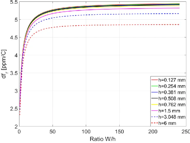
Figure 3.2 - Rectangular MPAs resonant at 915 MHz. Frequency drift for different antenna’s substrate in terms of substrate thickness and patch geometry ratio - u ... 27
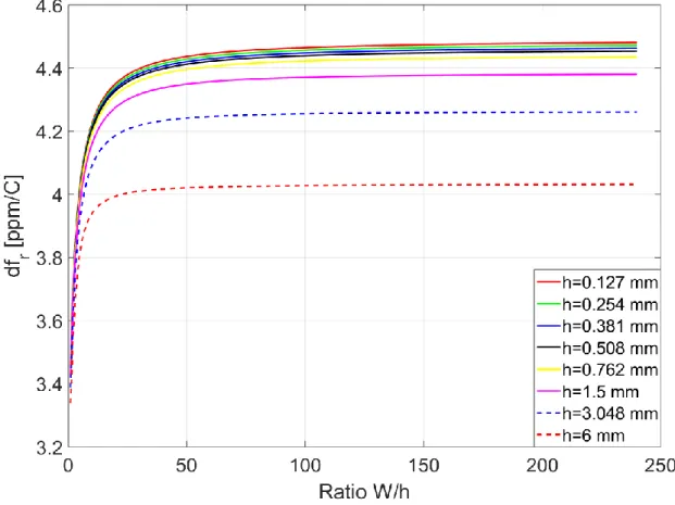
Figure 3.3 - Rectangular MPAs resonant at 5.8 GHz. Frequency drift for different antenna’s substrate in terms of substrate thickness and patch geometry ratio – u ... 28
Figure 3.4 - Frequency drift for rectangular MPAs resonant at 915 MHz on TMM10 substrate .. 29
Figure 3.5 - Frequency drift for rectangular MPAs resonant at 915 MHz on RO3035 substrate .. 30
Figure 3.6 - Frequency drift for rectangular MPAs resonant at 915 MHz on TMM10i substrate 31 Figure 3.7 - Frequency shift for CMPAs designed on different substrates ... 36
Figure 3.8 - Frequency drift of equilateral TMPAs designed on different substrate materials ... 39
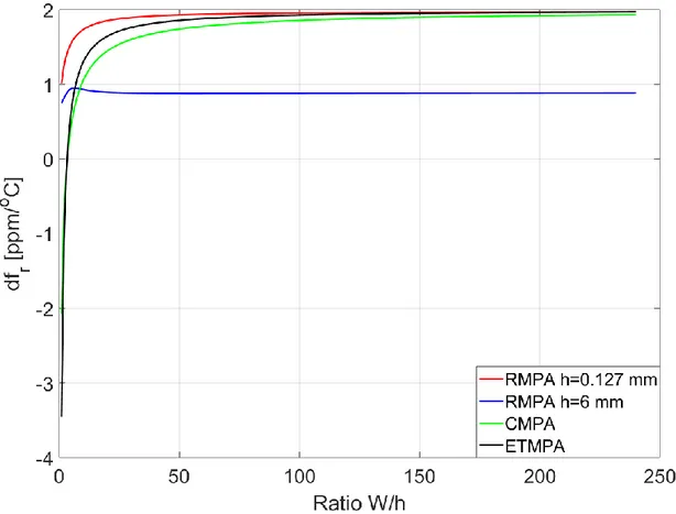
Figure 3.9 – Comparison frequency drifts for RMPA, CMPA and TMPA designed on TMM10 substrate ... 41
Figure 3.10 - Circuit model for analysing temperature impact on MPA resonance ... 42
Figure 3.11 - Comparison results between simulations, theory and circuit model ... 43
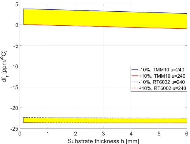
Figure 3.12 - Tolerance impact on RMPA frequency drift in terms of substrate thickness ... 45
Figure 3.13 - Tolerance impact on RMPA designed on RT/duroid 6002 substrate in terms of patch width to substrate thickness ratio ... 46
Figure 3.14 - Tolerance impact on RMPA designed on TMM10 substrate in terms of patch width
to substrate thickness ratio ... 47
Figure 3.15 - Tolerance impact on CMPA frequency drift ... 48
Figure 3.16 - Tolerance impact on ETMPA frequency drift ... 49
Figure 3.17 - Temperature Compensation Condition Given by eqn.(16) ... 55
Figure 3.18 - Structural transformation between Triangular, Circular and Rectangular Patch Geometries ... 56
Figure 3.19 - Temperature Compensation Conditions for RMPA, CMPA and RMPA antennas .. 57
Figure 3.20 - Set of fabricated microstrip antennas ... 59
Figure 3.21 - Measurement setup ... 60
Figure 3.22 - Temperature chamber coated with the absorbers ... 61
Figure 3.23 - Resonant frequency drift for RMPA fabricated on TMM10 substrate ... 62
Figure 3.24 - Resonant frequency drift for RMPA fabricated on RO6002 substrate ... 63
Figure 3.25 - Resonant frequency drift for CMPAs fabricated on the TMM10, RO3035, and RO6002 substrates ... 64
Figure 4.1 - Ice sample ... 68
Figure 4.2 - Ice dielectric properties measurement setup ... 69
Figure 4.3 - Measured ice permittivity ... 71
Figure 4.4 - Measured ice loss tangent ... 72
Figure 4.5 - Ice loading effect on resonant frequency of RMPA with parameter u=4 ... 73
Figure 4.6 - Ice loading effect on resonant frequency of RMPA with parameter u=80 ... 74
Figure 4.7 - Comparison frequency drifts ... 75
Figure 5.1 - Wireless temperature measuring system installation on a helicopter ... 77
Figure 5.2 - Block diagram of a wireless temperature sensor system ... 78
Figure 5.4 - Simulation results of received power for ASK modulated data ... 81
Figure 5.5 - Simulation of wireless system with FSK modulation ... 82
Figure 5.6 - Simulation results of received power for FSK modulated data ... 82
Figure 5.7 - Simulation of wireless system with QPSK modulation ... 83
Figure 5.8 - Simulation results of received power for QPSK modulated data ... 84
Figure 5.9 - Comparison of budget power simulation results ... 85
Figure 5.10 - Block diagram of an implemented system ... 87
Figure 5.11 – Built wireless temperature sensor system ... 88
LIST OF SYMBOLS AND ABBREVIATIONS
ASK Amplitude shift keying ADS Advanced Design System CAD Computer-aided design
CST Computer Simulation Technology CMPA Circular microstrip patch antenna
CEPT European Conference of Postal and Telecommunications Administrations CTE Coefficient of thermal expansion
EU European Union
ETSI European Telecommunication Standards Institute FEM Finite element method
FDTD Finite difference time domain
FCC Federal Communication Commission FSK Frequency shift keying
GPIO General purpose input output microcontroller pin GFSK Gaussian frequency shift keying
ITU International Telecommunication Union ISM Industrial, scientific, and medical
ICAO International Civil Aviation Organisation 𝐼ℎ Ice phase one
L Resonant length of rectangular microstrip patch LED Light emitting diode
MPA Microstrip patch antenna
MMIC Monolithic microwave integrated circuit
m Integer number
n Integer number
PTFE Polytetrafluoroethylene
PC Personal computer
PPS Polyphenyle-Nesulfide
QPSK Quadrature phase shift keying
RMPA Rectangular microstrip patch antenna RFID Radio frequency identification SDA Spectral domain approach SIW Substrate integrated waveguide SRD Short range device
T Temperature
TC Temperature coefficient
TMPA Triangular microstrip patch antenna UN United Nations
WRC World Radio Conference W Rectangular patch width 𝜀𝑟 Substrate permittivity 𝜀𝑒 Effective dielectric constant
𝛿𝑟 Temperature coefficient of the permittivity 𝛿𝜀 Temperature coefficient of effective permittivity 𝛿𝑐 Coefficient of temperature expansion of the copper
𝛿𝑥 Coefficient of temperature expansion of the substrate in the x-plane 𝛿𝑦 Coefficient of temperature expansion of the substrate in the y-plane
𝛿𝑧 Coefficient of temperature expansion of the substrate in the z-plane ∆𝑇 Incremental change in environment temperature
𝑓𝑟𝑇 Resonant frequency at referent temperature
𝑓𝑟𝑇1 Resonant frequency at some temperature point
CHAPTER 1
INTRODUCTION
1.1 Introduction
Icing presents a significant weather phenomenon causing one of the major operational troubles for airplanes and helicopters, thus affecting the ability for a stable flight [1] [2] [3]. Icing leads to increased aerodynamic drag and weight along with a reduction in lift and trust, with a direct impact on flight safety and economy [1] [2]. De-icing procedures prior to takeoff are often time-consuming and cause frequent delays at major airports [2]. Known examples are airports in Ottawa and Montreal region where icing conditions often force them to be partially or entirely closed [4]. Icing effect is often defined as the formation of ice when cold water droplets come in touch with the surface of object [5]. In the worst case, icing causes hazard to aircraft [6]. According to Federal
Aviation Administration (FAA) [7], NTSB Accident Database and Synopses [8], NASA Aviation Safety Reporting System [9] and other conducted statistical investigations [2] [10], accidents due
to icing occur very frequently. Similar and the only statistical study for Canada as the case of interest can be found in [11]. Given study represents the first analysis of icing accidents using Canadian database – Transport Canada Civil Aviation Daily Occurrence Reporting System (CADORS) database [12]. According to [11], the highest frequency of accidents is in Quebec and British Columbia with the most critical period of one month from December 10th to January 10th. Until present, methods for avoiding, preventing and decreasing accidents related to icing phenomenon rely on weather reports, forecast, pilot’s reports, observations, awareness and training to react in such situation [2]. Beside continuous improvement in forecast accuracy techniques for early warning in icing conditions, better icing analysis and detection are necessary [2]. Motivated by industry, this thesis research, as a part of the project - helicopter de-icing system, has the primary objective to design resonant frequency temperature-compensated microstrip patch antennas (MPA). Such temperature-compensated MPA will be exploited in the wireless temperature sensor network intended for the development of a helicopter de-icing system. Secondary product is related to the application of a temperature-compensated MPA for ice thickness sensing. This will be the first de-icing system deployed for helicopters.
1.2 Why Temperature Compensated MPA
MPA due to its compactness and versatility in electrical characteristics have found applications in a large number of commercial needs and sectors [13]. Today, MPAs can be found in airplanes, missiles, satellite links, mobile communications, local area networks and they represent an extension of microstrip circuits [14]. As an important part of transmitters and receivers, MPA characteristics affect the overall system performance. Due to their inherent resonance, they are characterized by a very narrow frequency bandwidth, typically a few percent [15]. In addition, the resonant frequency is strongly affected by dimensions of patch and substrate permittivity as well as working conditions [16]. It makes them susceptible to the fabrication process, design parameters tolerance and environmental conditions. Environmental conditions have a significant impact on MPA designed for outdoor applications. For the purpose of protection from water, humidity, dust and other outside factors, the MPAs are covered with superstrate layer called radome. It does not make them resistant to temperature variations and ice or snow loading effect. Temperature stability of resonant frequency is an important criterion, especially in military and airborne applications. Change in temperature causes drift in resonant frequency of MPA subsequently causing a band rejection or interference with adjacent bands. All the stated aspects point to accurate design techniques, as well as methods for decreasing MPA sensitivity on design parameters.
1.3 Research Objectives
Research objectives comprise of three parts:
- The first part focuses on a mathematical formulation of temperature variation effect on the resonant frequency of rectangular, circular and triangular patch geometries of MPA, leading to a temperature compensation technique. Tolerance analysis is addressed for the purpose of determining the resonant frequency drift sensitivity of a particular patch geometry on parameters, which are important for frequency stability. Creating a circuit model for analyzing temperature impact on the patch resonance will finalize the temperature impact analysis.
- The second part aims at investigating electrical properties of ice through measurements for the purpose of better characterization ice loading effect on MPA resonant frequency. Temperature-compensated antennas or antennas with reduced resonant frequency temperature sensitivity are employed as ice sensors for ice thickness determination.
- The third part deals with the design, prototyping, and testing of a wireless temperature sensor network intended for the development of a helicopter de-icing system. Specificity of application requires wireless temperature network elements assessment through a power budget analysis to ensure a reliable communication link.
1.4 Thesis Organization
The thesis is organized in six chapters. Introductory Chapter 1 offers the readers a broader view of project and guidelines for solving the problem. Contemporary literature review with all relevant information is briefly outlined in Chapter 2. The chapter summarizes temperature compensation techniques along their efficiency, advantages and disadvantages, addressing the system’s operating frequency band selection. The main contribution of the thesis is given in Chapter 3. This chapter is dedicated to a mathematical formulation of temperature impact on rectangular, circular and triangular microstrip patch antenna. Circuit model for analyzing temperature effect on antenna resonance is given. Tolerance analysis of the key parameters which affect antenna’s resonant frequency temperature dependence is carried out, showing the impact on resonant frequency temperature behaviour. Experimental and simulation results, along with theoretical results and those obtained by the circuit model, are presented. Resonant frequency temperature compensation condition is developed in Chapter 3. Chapter 4 deals with electrical properties of ice and MPA exploited as ice sensor. The design of a wireless temperature sensor network employing the temperature compensated MPAs is given in Chapter 5. Finally, Chapter 6 gives the summary of this research and proposes future work and possible improvements.
CHAPTER 2
BACKGROUND
This chapter presents a critical literature review on key research that describes the impact of temperature on resonant frequency of MPA. Furthermore, the developed techniques for resonant frequency temperature stabilization for MPA are described. Subsequently, this chapter guides us through frequency band selection for a wireless temperature sensor network intended for use on helicopters in North America and Europe.
2.1 Literature Review
To the best of the author’s knowledge, not much research has been done regarding the development of temperature compensation techniques for microstrip antennas, nor do the textbooks dealing with microstrip antennas discuss this topic. Additionally, majority of textbooks dealing with microstrip antennas do not discuss temperature impact on resonant frequency of MPA. As a rule, microstrip antennas are narrowly banded. In practice, it is very important to have a stable resonant frequency under a substantial temperature variation. Notably, only a few researchers have dealt with this problem and relevant details of research collection shall be presented below.
The primary research on this topic was initiated in 1981 by Bell Aerospace System Division [17]. This work experimentally investigated temperature impact on the resonant frequency of a rectangular MPA, and proposed a temperature compensation technique of the resonant frequency. The proposed technique resulted in a reduced sensitivity of antennas’ resonant frequency over temperature. According to this research, two factors mainly affected the resonant frequency. First was a copper expansion or contraction of a patch element. The second was a change in the effective dielectric constant of a substrate material. The resonant dimension of a patch element determines the operating frequency of a microstrip antenna. Due to the increase of temperature, the copper expansion of patch element results in a larger resonant dimension, thus decreasing the resonant frequency of MPA. Similarly, the opposite behaviour observed for temperature reduction. Another factor affecting the resonant dimension of patch element is the effective dielectric constant of a substrate material. Antennas designed on a Teflon-fiberglass dielectric substrate were used for experimental investigation. The Teflon-fiberglass substrate exhibited a decrease in dielectric constant, following an increase in temperature. This resulted in an increased resonant frequency with an increased temperature, i.e. making the effective dielectric constant smaller. Several
measurements were performed to confirm that the effective dielectric constant played a dominant role in the change of resonant frequency. By assuming that resonant length of a patch and effective dielectric constant of a substrate material varied linearly with temperature, a temperature-compensated MPA could be accomplished. By reducing the amount of dielectric material to a point where a change in the effective dielectric constant compensated a change in patch length, a resonant frequency would be less sensitive to temperature variations. However, this technique had no practical significance, as the frequency drift of 0.1 𝑀𝐻𝑧 and 0.6 𝑀𝐻𝑧 required the removal of 84% to 97% of dielectric material under a patch element. Such amounts of the removed dielectric material greatly reduced the robustness of a microstrip antenna.
Two decades after this research, the impact of temperature on the resonant frequency of MPA has once again received attention.
Another experimentally based research study [18] provided an extensive review of the factors that affected a resonant frequency of MPA in terms of temperature. Two major problems encountered with the modern microstrip antenna design were identified and studied in detail. The first major problem was unknown temperature dependence on the substrate electrical parameters. The second major problem was discrepancy between actual substrate parameter’s value and those specified in manufacturers’ datasheets. These factors were reflected in common design practices of microstrip antennas, preventing design engineers from precisely predicting the behaviour or design of MPA for non-friendly or harsh conditions. In datasheets, the relative dielectric constant is specified within a certain tolerance range at room temperature and one frequency point while the dissipation factor is specified as its maximum value at one frequency point and room temperature. A major drawback of the datasheets is the fact that they neglected the drift of electrical parameters under temperature changes. Generally speaking, datasheets provide information, such as thermal coefficient of the dielectric constant, within 0℃ to +100℃ temperature range as an average value. Notably, this temperature dependence is neither linear nor symmetric. This is the main reason for discrepancies between the actual behaviour of the microstrip antenna and those predicted by computer-aided design (CAD) tools. The discrepancies can be larger if actual electrical substrate parameters are frequency dependent. One of the main reasons for incompleteness and incorrectness of manufacturers’ data is the lack of accurate measurements of material’s electrical parameters on manufacturing line [18]. For the purpose of determining actual electrical parameters of substrates and their impact on design, behaviour and temperature stabilization of microstrip antenna, the
following substrates are investigated: Teflon-based, ceramic-based and quartz-fibre substrates. The investigated substrate parameters are relative dielectric constant and loss tangent. Substrates have been exposed to temperature variations ranging from −60℃ to + 80℃. Additionally, their behaviour has been observed at four frequencies between 800 𝐾𝐻𝑧 and 10 𝐺𝐻𝑧. Measurements of these parameters were performed precisely and under controlled conditions with high quality manufactured substrate samples. The accuracy of measurements was around 1.5% for the dielectric constant and 3% for loss tangent, regardless of temperature. Based on the measured results under temperature impact on measured parameters, substrates were divided into four categories: A, B, C, D. Such substrate categorization was not possible in datasheets due to the lack of information. Each category was characterized by specific behaviour of certain electrical parameters. The results of Category A and B, along with their discrepancies from manufacturers’ specified values, are shown in Figure 2.1.
Figure 2.1 - Category A and B substrate dielectric constant temperature dependence. The shaded area is the dielectric constant range specified by the manufacturer [18], © [1999] IEEE Category A included Teflon-glass substrates, and its typical representatives were Ultralam 2000 and CuClad 250 LX. This category has shown an almost constant negative temperature coefficient
of the dielectric constant over the entire temperature range except the temperature range where the phase transition of glass occurred. Substrates in category B were also Teflon-glass based but they had a dielectric constant gradient which differs in at least two temperature subranges.
Category B of substrate materials was characterized by an almost temperature independent dielectric constant in the lower temperature range, while showing a strong dependence in higher temperature ranges. Representatives of this category were RT/Duroid 5880 and TLX-8 substrates. The changes in dielectric were 9.7% for category A, and 8% for category B over the entire temperature range. Comparison of the measured values of the dielectric constants with those specified by the manufacturers revealed big differences. Measurements also disclosed a phase transition that has not been specified by the manufacturer. The measurements of these two categories showed no frequency dependence of electrical parameters within the considered temperature range. Measurement results for substrate categories C and D are shown in Figure 2.2 and Figure 2.3. Substrate categories C and D included ceramics substrates.
Figure 2.2 - Category C substrate dielectric constant and loss temperature dependence along manufacturer’s value specifications [18], © [1999] IEEE
Substrates of Category C were characterized by uniformly dispersed ceramic filler in Teflon matrix. Representatives were RT/Duroid 6010 and AR1000. Measurement results for this category of substrate materials showed changes of 6.9% in the dielectric constant over all temperature ranges and negligible frequency dependence up to temperatures of 25℃. Slight variations of about 0.8% in measured parameters with frequency occurred in higher temperature ranges. Values of the dissipation factor complied with the manufacturer’s specifications only for temperatures below 10℃. For temperatures over 10℃, there was a significant divergence from the specified datasheet value. It was found to be 5.2 times larger when compared to the maximum value specified by the manufacturer.
The dielectric constant of Category D substrate materials, Figure 2.3, compared to the Category A, B, and C was characterized by the smallest variation in the dielectric constant and ultralow dissipation factor. The observed dielectric constant variation was less than 4.3%.
Figure 2.3 - Category D substrate dielectric constant and loss temperature dependence [18], © [1999] IEEE
A comprehensive analysis of various microstrip antennas exposed to large temperature variations was possible based on accurate data and temperature behavior of particular electrical parameters. Dual-feed aperture coupled microstrip antennas were fabricated, combining four substrate categories A, B, C, and D in different ways to create a temperature-compensated antenna. Combinations of B-D or C-D categories were observed to have the best temperature behaviour. The achieved relative frequency drift for these combinations was between 0.9% and 1%. It was observed that the combination of Teflon-glass substrate materials was unacceptable for microstrip antennas used in large temperature variation applications.
In addition to experimental investigations of temperature impact on microstrip antenna’s resonant frequency, theoretical analyses employing an accurate transmission line model [19], as well as rigorous numerical techniques, such as Spectral Domain Approach [20] are employed.
In the paper [19], the improved linear transmission line model was used to analyze rectangular, circular, and triangular microstrip patch geometries for the first time. The improved linear transmission line model represents an appropriate mean for the visualization temperature effects on a resonant frequency of MPA. The simulated effects due to variation in parameters such as length, width, thickness and dielectric constant caused by temperature only confirmed the previously conducted experimental analysis. A temperature sensitivity analysis has been completed for antennas designed on three different commercially available substrates: RT/Duroid 5500, RT/Duroid 6006 and Epsilam 10 in −40℃ to + 60℃ temperature range. The analysis of these substrates showed that microstrip antennas designed on substrates with a lower dielectric constant and lower thermal coefficient of dielectric constant were less sensitive to temperature variations. It was also observed that the effect of variations in substrate thickness on resonant frequency was negligible.
In research [20] that analyzed temperature variations on a resonant frequency of MPA, a more rigorous method was employed – spectral domain approach (SDA). Frequency drift results obtained by the spectral domain approach coincided with the analysis results obtained by the transmission line method [19] which required less mathematical complexity and computation time. An entirely different approach to temperature compensation for the frequency drift of microstrip antenna material was proposed in [21]. In that research, temperature-compensated thermoplastic high dielectric constant microwave laminate was synthesized. A high dielectric constant was
desirable for miniaturization of the antenna element. Proposed new compositions were made by mixing suitable ceramics and polymers. Polyphenylene-Sulfide (PPS) was selected as a polymer matrix because of low losses and low moisture absorption. The first composite was created by adding Strontium-Titanate ceramic into PPS matrix providing a high dielectric constant and low loss tangent at a relatively low composition volume. The Strontium-Titanate/PPS composition could not satisfy the desired temperature compensation. Measurement results of frequency drift made on manufactured microstrip patch antennas on this composition showed a 4% frequency drift at the temperature of 100℃. Hence, despite a good electrical characteristic, this composition was not satisfactory. This dissatisfaction was attributed to a large negative temperature coefficient of the Strontium-Titanate composition. To compensate for this effect in the PPS-Strontium-Titanate composition, new ceramic was added. Mica and Alumina, which both possess a positive temperature coefficient of dielectric constant were used. By fine-tuning of the new composition: Strontium Titanate/Mica/PPS, it was possible to accomplish + 0.8 % variation in dielectric constant over −50℃ to +100℃ temperature range. Loss tangent of this new composition was not influenced by temperature variations. By adding more Mica into the composition, a better temperature compensation could be achieved. Mica had an advantage over Alumina due to its lower coefficient of thermal expansion for an equal volume of alumina, which helped Mica filled substrates to better match their temperature expansion coefficient with copper. For the experimental validation, 50 rectangular microstrip patch antennas were fabricated and measured. Measurement results showed the resonant frequency variation ofaround 1% in −40℃ to + 100℃ temperature range.
The patent [22] proposed a passive technique for the compensation of resonant frequency of microstrip patch antennas over a range of temperatures. This passive method for compensating the resonant frequency change overcomes the shortcomings of active compensation method. The active compensation method based on connecting high-Q GaAs varactor diodes at one of the antenna radiating edges is expensive and requires a thick substrate for the accommodating diode. This also requires an additional power supply to bias the diode and to vary its capacitance for the purpose of the resonant frequency compensation. The passive compensation method emphasizes microstrip antennas made on Teflon-based substrates. In these structures, resonant frequency tends to be increased along with an increase in temperature due to the dominance of the negative coefficient of substrate permittivity over copper thermal expansion. The proposed passive
compensation scheme is relatively inexpensive and based on the use of temperature dependent capacitors. The bi-metallic plate capacitors are adjusted on the radiating edges of the microstrip antenna. A change in capacitive loading due to temperature results in a variation of the effective electrical size of patch element, resulting in frequency compensation.
None of these researches quantify or provide equations for the temperature-compensated MPA. In this thesis along with the proposed design methodology for temperature-compensated MPA, the temperature impact on a resonant frequency of fundamental and high order modes is quantified and mathematically described.
Despite a lack of literature in temperature compensation techniques for resonant frequency of MPA, numerous compensation techniques are available for resonant cavities and filters [23] [24] [25]. Some of compensation techniques use different materials to preserve a cavity size with temperature variations [26], while other use field perturbation techniques [27]. These techniques can serve as a guideline for temperature compensation MPA, as microstrip antenna can be modelled as a resonant cavity [16] [14].
A reference of interest [23] is a starting point for developing theory in this thesis. This research deals with substrate integrated waveguide (SIW) cavities and filters. A new temperature compensation technique based on adequate substrate properties selection, providing self-temperature frequency drift compensation was proposed and demonstrated. In order to accomplish this, an appropriate ratio between the coefficient of thermal expansion of copper and the thermal coefficient of substrate dielectric constant was utilized. From the theoretical analysis presented in this work, it is possible to accomplish a complete temperature compensation when the thermal coefficient of dielectric constant reaches nearly two times the copper’s thermal expansion coefficient, but opposite in sign. Experimental validation of that conclusion was done by manufacturing three cavities with different materials and by one microstrip and SIW fourth-order filter. The cavities were designed to operate at the frequency of 10 𝐺𝐻𝑧. To ensure the same conditions for all cavities, they were designed to have the same coupling and the same number of via-holes. Cavities and filters were measured over the −40℃ to + 80℃ temperature range. Substrates used in this experimental validation were RT/Duroid 6002, RT/Duroid 6010 and TMM10. Substrate RT/Duroid 6002 was used as a reference for assessing the compensation technique as it has the minimal temperature coefficient of permittivity among all substrates. Hence,
it should cause the minimum frequency drift. The substrate RT/Duroid 6010 has the largest variations in dielectric constant. Substrate TMM10 was used to verify the compensation technique as it nearly satisfies the compensation condition. All of these substrates have expansion coefficient that matches copper’s expansion coefficient. The inconsistency between manufacturer’s data and the real values of substrate electrical parameters, as well as the lack of information regarding their behaviour with temperature were stressed as one of the design and accurate analysis problems. The experiments revealed that cavities fabricated on TMM10 had the best stability in overall temperature range even better than RT/Duroid 6002 with the lowest temperature coefficient of dielectric constant and permittivity among all used substrates. The obtained frequency drift for TMM10 was 8 𝑝𝑝𝑚/℃. Cavities manufactured on other materials exhibited frequency drift: 54 𝑝𝑝𝑚/℃ for RT/Duroid 6002 and 273 𝑝𝑝𝑚/℃ for RT/Duroid 6010. These experimental results were in good agreement with theoretically predicted ones: 2 𝑝𝑝𝑚/℃ for TMM10, 22 𝑝𝑝𝑚/℃ for RT/Duroid 6002 and 188 𝑝𝑝𝑚/℃ for RT/Duroid 6010. The reason for the difference between the measurement and predicted results was an inconsistent and non-precise parameters value specified by the manufacturer. Experimental results carried out for the SIW, and a coupled-line microstrip filters also validated the compensation technique. Frequency variations were larger for microstrip filter due to condensation and moisture absorption that strongly affects the losses of microstrip lines. SIW structure was less sensitive on moisture absorption due to closed architecture, showing a very low temperature drift compared to its microstrip counterpart.
2.2 Frequency Regulations and Frequency Band Selection
Selecting appropriate operating frequency band is of crucial importance for the targeted project application. The importance of the frequency selection is presented as a brief review.
In early 1912, the need for frequency spectrum regulation raised for the first time due to congestion in the use of wireless telecommunication at sea [28]. During that time in the United States, the Secretary of Commerce was given right of administrating and licensing radio stations. However, with the emergence of broadcast radio, this framework did not work well, causing interference between radio stations in the broadcast market. Reason for that was recognized as de facto possession of frequency spectrum: the each first broadcaster in any given frequency band automatically owned a full right on that band [28]. Hence, it was necessary for more precise frequency spectrum regulations. As a final word on this problem in 1927, U.S. Congress passed the Radio Act bill under which Federal Communications Commission (FCC) was established. This regulatory body has the highest responsibility for the managing frequency spectrum, granting licensing, control users of radio spectrum and so on.
All other countries around the world followed this model of FCC in establishing their national regulatory agency to control and manage frequency spectrum.
For the purpose of harmonization, i.e. establishing the same frequency rules, regulations, protocols and standards all around the world, coordination between national regulatory agencies is done by the International Telecommunication Union (ITU). ITU is a specialized agency of United Nations (UN) and the member of UN Development Group, intended for information and communication technologies [29] [30]. ITUs main tasks are [29]:
- Coordination of global frequency spectrum usage - Allocation of satellite orbits
- Developing and assistance in technical standards
- Striving for improvement in access to information and communication technologies
Once in every three years, ITU organizes the World Radiocommunication Conference (WRC) toward the world consensus on radio regulations [28]. Besides WRC, ITU also organizes
exhibitions and forums to bring together representatives of government and industry for exchanging experiences, ideas, knowledge and technology [29] [30].
From this review, we can understand the importance and intention dedicated to frequency spectrum utilization. Hence, the primary purpose is to avoid interference between devices which operate within the same or adjacent frequency bands, ensuring quality operation and service.
For this project, the frequency bands of interest are Industrial, Scientific and Medical (ISM) bands. These bands are unlicensed [28]. Unlicensed means that product intended for these bands do not need require a license from the telecommunication regulatory authorities. However, unlicensed does not mean unregulated, and devices need to meet strict regulations. Some of the regulations [31] imposed by regulatory agencies are presented below for the reference:
- “Operating frequency - Bandwidth
- Radiated power (depends on the frequency range, specific application, services and systems already used or planned to be used in these bands)
- Spurious emission - Modulation methods
- Transmission duty cycles”, [31].
Regarding definition, these bands are reserved for industrial, scientific and medical purposes other than telecommunications [31]. It means that radio communication services operating within these bands must accept harmful interference from ISM devices [30]. ISM bands are defined under ITU Radio Regulations (Article 5) in footnotes 5.138, 5.150 and 5.280 of the Radio Regulations, and they are summarized in Table 2.1.
Table 2.1 - ISM frequency bands
Frequency band [MHz] Centre frequency 𝑓𝑐 [MHz]
6.765-6.795 6.78 433.05-434.79 433.92 61000-61500 61250 122000-123000 122500 244000-246000 245000 13.553-13.567 13.56 26.957-27.283 27.12 40.66-40.7 40.68 902-928 915 2400-2500 2450 5725-5875 5800 24000-24500 24125
The frequencies in the green part of the table are intended for ISM devices under special conditions and provisions. They must not affect existing radio communication services in those bands [31]. The frequencies in the second part of table coloured orange are free for usage by radio communication services which must accept harmful interference caused by ISM appliances and they are not protected by a regulatory body [31].
In European Union (EU), the organization responsible for governing frequency spectrum is
European Telecommunication Standards Institut (ETSI), recognized by EU as European
Standardization Organization [31]. Unlike for North America’s regulations, in EU there is one special category called Short Range Devices (SRD). SRD are low power radio communication systems with a typical range of operation up to 100 meters [31]. The well-known RFID systems belong to this SRD category. SRD has low capacity to interfere other communication equipment, which makes them licence free. It is very important to stress that under the meaning of ITU Radio Regulations (Article 1), SRD are not considered a Radio Service. Exactly, there is no definition for SRD devices under ITU Radio Regulations. However, under EU’s regulations for most efficient implementation of these devices the following categories [31] are recommended:
- “Non-specific short-range devices - Tracking, tracing and data acquisition
- Wideband data transmission systems - Railway applications
- Alarms
- Inductive applications - RFID
- Wireless audio applications - Radio microphones
- Radio determination
- Road Transport and traffic telematics”, [31].
Use of SRD bands is governed by ERC Recommendation 70-03 [32]. This recommendation sets out spectrum management requirements to allocate frequency bands, maximum radiated power, modulation type, occupied bandwidth, duty cycles and important technical parameters for SRD devices.
A very important fact for this project stated in ERC Recommendation 70-03 is cited here:
“The CEPT has considered the use of SRD devices on board aircraft and it has concluded that, from the CEPT regulatory perspective, such use is allowed under the same conditions provided in the relevant Annex of Recommendation 70-03. For aviation safety aspects, the CEPT is not the right body to address this matter which remains the responsibility of aircraft manufacturers or aircraft owners who should consult with the relevant national or regional aviation bodies before the installation and use of such devices on board aircraft [32].”
ITU Radio Regulations under Article 15, also touches issue regarding aircraft safety regarding frequencies. Footnote 15.8 states:
“Special consideration shall be given to avoiding interference on distress and safety frequencies, those related to distress and safety identified in Article 31 and those related to safety and regularity of flight identified in Appendix 27. (WRC - 07) [30]”
Onboard aircraft SRDS must obey both radio and aeronautical regulations. Radio regulations are responsible for devices to meet national or regional requirements, regarding radiated power and
potential impact on other services, while aeronautical regulations make sure that these devices will not cause a safety hazard to aircraft. As stated in ERC Recommendation 70-03, SRDs used inside or outside the aircraft if met the specified operational and technical conditions; there are no additional radio regulatory issues. However, radio regulations do not affect the responsibility of aviation body who issue safety flight certification. Hence, the radio regulations should not be seen as approval for operation until the safety certification is issued.
International Civil Aviation Organization (ICAO) has issued the following statement regarding
SRD usage:
“Oppose operation of short-range devices in any bands allocated to aeronautical services. Support the inclusion in the Radio Regulations of appropriate regulatory provisions to ensure that short-range devices, operating outside of aeronautical bands, do not cause harmful interference to aeronautical systems operating in allocated aeronautical bands. [33]”
As a final word on using SRDs on-board aircraft, the following citation will be summarized: “To use SRDs on board aircraft, regulators may allow usage under conditions; however, for aviation safety aspects, the right bodies to address this matter remains the responsibility of aircraft manufacturers or aircraft owners who should consult with ICAO, the relevant regional and national bodies, before installing SRDs on aircraft. [34]”
Taking into considerations all the above facts regarding SRD and ISM devices, comparing appropriate frequency bands in Canada, United States and European Union, it appears that the most appropriate bands for usage are in 2.4 𝐺𝐻𝑧 frequency range.
CHAPTER 3
TEMPERATURE COMPENSATED MICROSTRIP PATCH
ANTENNA
3.1 Introduction
This chapter contains the main contribution to this thesis work. At the beginning of the chapter, the characteristics of MPA are reviewed, and followed by a mathematical formulation of temperature impact on fundamental and high order modes of rectangular, circular, and triangular MPA. Theoretically obtained results for resonant frequency drift are shown, compared and discussed. Drawn conclusions from the theoretically obtained results for frequency drift are verified by electromagnetic simulator-based simulations. Performed simulations support the formulated theory. In addition to electromagnetic simulations, an accurate circuit model for analysing the temperature impact on resonant frequency of MPA is proposed. According to the resonant frequency drift results the optimal substrates for an antenna design are selected. Conducted tolerance analysis emphasizes the key parameters which affect a resonant frequency temperature behavior for rectangular, circular, and triangular MPA. The resonant frequency temperature compensation condition is derived based on the mathematically formulated temperature dependence of the resonant frequency. Experiments are conducted in support of the results derived through the theoretical work and simulations.
3.2 Microstrip Patch Antenna Characteristics
Microstrip patch antenna is one of the simplest radiating structures [15] [35]. It is a resonant structure made of electrically thin dielectric sheet with patch metallization on one and ground on the other side [14]. The patch can take any shape but commonly used ones are rectangular, circular, and triangular. It consist of a very thin metallization 𝑡 ≪ 𝜆0 and substrate thickness - a small
fraction of wavelength 0.003𝜆0 ≤ ℎ ≤ 0.05𝜆0, where 𝜆0 is free space wavelength [15]. Based on
the substrate thickness, microstrip antennas can be divided into electrically thin and electrically thick antennas ℎ ≥ 0.02𝜆0 [15]. For the substrate thicknesses of ℎ ≥ 0.11𝜆0 coaxial-probe feed
microstrip antenna ceases to resonate due to the inductive effect of the feed [36]. Dielectric substrate materials with a dielectric constant in the range 2 ≤ 𝜀𝑟 ≤ 12 are widely used for the
patch antennas. Considering the radiation efficiency, materials with lower dielectric constant are preferred over materials in the upper dielectric constant range due to lower dielectric losses and
better performances of antenna [14] [15] [16]. Materials with a higher dielectric constant are suitable for the microstrip antenna miniaturization at the cost of radiation efficiency. Since the rectangular MPA is a starting point for the theory derived in this thesis, its geometry is shown in Figure 3.1.
W
L
h
t
x
y
z
(x, y)
ɛ
rFigure 3.1 - Rectangular MPA geometry
Although MPAs are characterized by compactness and versatility, compared with other antenna structures they are not optimal in terms of electrical properties. Nevertheless, MPAs offer a lot of advantages over other radiating structures. Some of the advantages and disadvantages are listed below [13] [14] [15].
Advantages:
- low profile
- conformable to planar and non-planar surfaces - simple and inexpensive
- mechanically robust
- versatile in terms of polarization and radiation pattern - light weight
- easy to fabricate and integrate with active devices - reproducible and
- flexible design
Disadvantages:
- narrow frequency bandwidth - low efficiency
- low power handling - poor polarisation purity - spurious feed polarization
Narrow bandwidth of such structures triggered the researchers to develop various analytical techniques and models to accurately predict antenna’s resonant frequency and behaviour. The numerous proposed models can be divided into numerical (MoM, FEM, FDTD, SDA, Variational Techniques etc.) and analytical (Transmission-line model and Cavity model) models. The numerical techniques are very accurate and versatilely used to design and analyse MPA, but they involve an execution of complex codes on a computer system, demanding greater computational time and memory. Also, they do not give any physical insights unlike analytical techniques. The analytical techniques are suitable for CAD tools for a quick estimation of antenna’s characteristics, behaviour and optimisation but they are less accurate and versatile compared to their numerical counterpart. Transmission-line model is the simplest one when compared to others; it is satisfyingly accurate and provides a very good physical insight [15]. Transmission-line model in its fundamental form cannot be used to analyze higher order modes (except fundamental mode harmonics) and arbitrary shaped patches (patches of a shape other than rectangular), but with minor modifications it is suitable for arbitrary shaped patches [37] [38] [39] [40] [41] as well as for multi-layered structures [42] [43].
3.3 Mathematical Formulation of Temperature Impact on MPA’s Resonant
Frequency – Frequency Drift
This section provides a mathematical expression of the temperature impact on the resonant frequency behaviour of a rectangular, circular and triangular MPA. The first three subsections describe the temperature dependence of MPA’s resonant frequency for rectangular, circular, and triangular patch geometries. MPA are fabricated on different substrates and different substrate thicknesses in terms of particular parameters. The last subsection summarizes and compares results from the previous subsections for the substrates that allow antennas to exhibit the best resonant frequency behaviour.
3.3.1 Rectangular MPA Frequency Drift
The resonant frequency drift of the rectangular MPA on different substrates, substrate thicknesses and resonant frequencies for the fundamental mode and its harmonics is mathematically described and discussed. A derived theory is verified through simulations in CST electromagnetic simulator software.
3.3.1.1 Mathematical Formulation
The resonant frequency of rectangular microstrip patch antenna (RMPA) in its fundamental 𝑇𝑀10
mode is given by:
𝑓𝑟 = 𝑐
2(𝐿 + 2𝑋)√𝜀𝑒 (1)
Due to clarity in following derivation in eqn.(1) 𝑋 denotes the patch length extension ∆𝐿 due to fringing field effect. The term in bracket represents the resonant effective length of a patch and also due to clarity in the following derivation the notation 𝐿𝑒 = 𝐿 + 2𝑋 is introduced.
Representing eqn.(1) as a function of three variables 𝐿, 𝜀𝑒 and 𝑋, the change in resonant frequency
∆𝑓𝑟 =𝜕𝑓𝑟 𝜕𝐿∆𝐿 + 𝜕𝑓𝑟 𝜕𝜀𝑒∆𝜀𝑒+ 𝜕𝑓𝑟 𝜕𝑋∆𝑋 (2)
Derivatives in eqn.(2) are given by:
𝜕𝑓𝑟 𝜕𝐿 = − 𝑓𝑟 𝐿𝑒 𝜕𝑓𝑟 𝜕𝜀𝑒 = − 𝑓𝑟 2𝜀𝑒 𝜕𝑓𝑟 𝜕𝑋 = − 2 𝐿𝑒𝑓𝑟 (3)
Substituting derivatives from eqn.(3) into eqn.(2), the incremental change in resonant frequency is obtained, eqn.(4): ∆𝑓𝑟 𝑓𝑟 = − 1 𝐿𝑒∆𝐿 − 1 2𝜀𝑒∆𝜀𝑒− 2 𝐿𝑒∆𝑋 (4)
Equation eqn.(4) given in this form is impractical and useless. Equation eqn.(4) has to be reduced to a suitable form in terms of design and temperature parameters.
For the effective dielectric constant 𝜀𝑒 in eqn.(1) the frequency dependence is assumed, which is
given by eqn.(5):
𝜀𝑒 = 𝜀𝑟−
𝜀𝑟− 𝜀𝑒0
1 + 𝑃 (5)
𝜀𝑒0− is a quasi-static effective dielectric constant given by eqn.(6) 𝑃 − is a frequency dependent term specified in [44]
Of all existing equations for a quasi-static effective dielectric constant, the simplest one is used, without affecting the final result.
𝜀𝑒0 =(𝜀𝑟+ 1) 2 + (𝜀𝑟− 1) 2 1 √(1 + 12𝑊)ℎ (6)
Given eqn.(6) is valid for the fundamental mode and its harmonics imposing in that way a validity constrain on a final result.
Small increment ∆𝜀𝑒 in effective dielectric constant 𝜀𝑒 given by eqn.(5) under approximation 𝑃
term as a constant, can be found as:
∆𝜀𝑒 = 𝜕𝜀𝑒 𝜕𝜀𝑟 ∆𝜀𝑟+ 𝜕𝜀𝑒 𝜕𝜀𝑒0 ∆𝜀𝑒0 (7)
Derivatives in eqn.(7) are given by:
𝜕𝜀𝑒 𝜕𝜀𝑟 = 1 − 1 1 + 𝑃 𝜕𝜀𝑒 𝜕𝜀𝑒0 = 1 1 + 𝑃 (8)
The incremental change in quasi-static effective dielectric constant based on eqn.(6) is:
∆𝜀𝑒0 =𝜕𝜀𝑒0 𝜕𝜀𝑟 ∆𝜀𝑟+ 𝜕𝜀𝑒0 𝜕𝑊 ∆𝑊 + 𝜕𝜀𝑒0 𝜕ℎ ∆ℎ (9)
𝜕𝜀𝑒0 𝜕𝜀𝑟 =1 2 [ 1 + 1 √(1 + 12𝑊)ℎ ] 𝜕𝜀𝑒0 𝜕𝑊 = 3(𝜀𝑟− 1) ℎ 𝑊2 1 (1 + 12𝑊)ℎ √(1 + 12𝑊)ℎ 𝜕𝜀𝑒0 𝜕ℎ = −3(𝜀𝑟− 1) 1 𝑊 1 (1 + 12𝑊)ℎ √(1 + 12𝑊)ℎ (10)
Due to clarity in the following derivation and derived equations readability, the next notation is introduced: 𝐴 = 3(𝜀𝑟− 1) 1 (1 + 12𝑊)ℎ √(1 + 12𝑊)ℎ 𝜕𝜀𝑒0 𝜕𝜀𝑟 = 𝑘 (11)
The next term which has to be determined in eqn.(4) is the increment of the patch length extension due to fringing field effect, ∆𝑋. Equation used for the patch length extension eqn.(12) is not currently the most accurate, but it is suitable for calculations (carrying out maths).
∆𝐿 = 𝑋 = 0.412ℎ (𝜀𝑒+ 0.3)( 𝑊
ℎ + 0.264) (𝜀𝑒− 0.258)(𝑊ℎ + 0.813)
(12)
Representing eqn.(12) as a function of three variables 𝜀𝑒, 𝑊 and ℎ, a small increment ∆𝑋 in the
∆𝑋 = 𝜕𝑋 𝜕𝜀𝑒∆𝜀𝑒+ 𝜕𝑋 𝜕𝑊∆𝑊 + 𝜕𝑋 𝜕ℎ∆ℎ (13)
Derivatives in eqn.(13) are given by:
𝜕𝑋 𝜕𝜀𝑒 = − 𝐶𝑥𝑒 2(𝜀𝑒− 0.258)2 𝜕𝑋 𝜕𝑊= 𝐶𝑥𝑤 0.6 ℎ(𝑊ℎ + 0.813)2 𝜕𝑋 𝜕ℎ = 𝐶𝑥ℎ 0.2 (𝑊ℎ + 0.813) +𝑊ℎ (𝑊ℎ + 0.2) (𝑊ℎ + 0.813)2 (14) with coefficients: 𝐶𝑥𝑒 = 0.412ℎ (𝑊ℎ + 0.264) (𝑊ℎ + 0.813) 𝐶𝑥𝑤 = 0.412ℎ (𝜀𝑒+ 0.3) (𝜀𝑒− 0.258) 𝐶𝑥ℎ = (𝜀𝑒+ 0.3) (𝜀𝑒− 0.258) (15)
Substituting equations eqn.(7) to eqn.(14) into eqn.(4) the fractional change in the resonant frequency due to change in some of design parameters 𝐿, 𝜀𝑟 and ℎ is obtained and given by eqn.(16).
∆𝑓𝑟 𝑓𝑟 = − ∆𝐿 𝐿𝑒 + ( 𝐶𝑥𝑒 𝐿𝑒(𝜀𝑒− 0.258)2 − 1 2𝜀𝑒) {𝐾𝑝∆𝜀𝑟+ 𝐴𝑝( ℎ 𝑊2∆𝑊 − 1 𝑊∆ℎ)} (16)
![Figure 2.1 - Category A and B substrate dielectric constant temperature dependence. The shaded area is the dielectric constant range specified by the manufacturer [18], © [1999] IEEE Category A included Teflon-glass substrates, and its typical representa](https://thumb-eu.123doks.com/thumbv2/123doknet/2352941.36678/25.918.210.731.503.942/dielectric-temperature-dependence-dielectric-specified-manufacturer-substrates-representa.webp)
![Figure 2.2 - Category C substrate dielectric constant and loss temperature dependence along manufacturer’s value specifications [18], © [1999] IEEE](https://thumb-eu.123doks.com/thumbv2/123doknet/2352941.36678/26.918.164.752.525.981/category-substrate-dielectric-constant-temperature-dependence-manufacturer-specifications.webp)
![Figure 2.3 - Category D substrate dielectric constant and loss temperature dependence [18], © [1999] IEEE](https://thumb-eu.123doks.com/thumbv2/123doknet/2352941.36678/27.918.169.755.503.954/figure-category-substrate-dielectric-constant-temperature-dependence-ieee.webp)