HAL Id: hal-00014519
https://hal.archives-ouvertes.fr/hal-00014519
Submitted on 14 Dec 2005
HAL is a multi-disciplinary open access archive for the deposit and dissemination of sci-entific research documents, whether they are pub-lished or not. The documents may come from teaching and research institutions in France or abroad, or from public or private research centers.
L’archive ouverte pluridisciplinaire HAL, est destinée au dépôt et à la diffusion de documents scientifiques de niveau recherche, publiés ou non, émanant des établissements d’enseignement et de recherche français ou étrangers, des laboratoires publics ou privés.
From colloidal dispersions to colloidal pastes through
solid/liquid separation processes
J.B. Madeline, Martine Meireles, J. Persello, C. Martin, R. Botet, R.
Schweins, B. Cabane
To cite this version:
J.B. Madeline, Martine Meireles, J. Persello, C. Martin, R. Botet, et al.. From colloidal dispersions to colloidal pastes through solid/liquid separation processes. Pure and Applied Chemistry, De Gruyter, 2005, 77, pp.1369. �hal-00014519�
From colloidal dispersions to colloidal pastes
through solid/liquid separation processes
J.B. Madeline1, M. Meireles1, J. Persello2, C. Martin3, R. Botet4, R. Schweins5, B. Cabane6
1 Laboratoire de Génie Chimique, CNRS UMR 5503, 118 route de Narbonne, 31062 Toulouse cedex 4, France
2 LCMI, Université de Franche-Comté, 16 route de Gray, 25030 Besançon, France.
3 Laboratoire de Rhéologie, Université Joseph Fourier, Grenoble I, Institut National Polytechnique de Grenoble, CNRS UMR 5520, BP 53, 38041 Grenoble Cedex 9, France 4 Laboratoire de Physique des Solides, CNRS UMR 8502, Université Paris-Sud, 91405
Orsay, France
5 ILL, BP 156, 38042 Grenoble cedex 9, France
Abstract
Solid-liquid separation is an operation that starts with a dispersion of solid particles in a liquid, and removes some of the liquid from the particles, producing a concentrated solid paste and a clean liquid phase. From a conceptual point of view, it is similar to thermodynamic processes where pressure is applied to a system in order to reduce its volume. In dispersions, the resistance to this compression depends on interactions between the dispersed particles.
The first part of this work deals with dispersions of repelling particles, which are either silica nanoparticles or synthetic clay platelets, dispersed in aqueous solutions at high pH and low ionic strength. In these conditions, each particle is surrounded by an ionic double layer, which repels other double layers. This results in a structure with strong short-range order. At high particle volume fractions, the overlap of double layers generates large osmotic pressures; these pressures may be calculated, through the cell model, as the cost of reducing the volume of each cell. The variation of osmotic pressure with volume fraction is the equation of state of the dispersion. The second part of this work deals with dispersions of particles that attract each other. The particles are silica nanoparticles, dispersed in water and flocculated by addition of multivalent cations. This produces large bushy aggregates, with fractal structures that are maintained through interparticle surface-surface bonds. As the paste is submitted to increasing osmotic pressures, most bonds are retained, but reordering processes at the scale of 2-20 diameters cause the structure to collapse. The final structure is made of dense grains immersed in a nearly homogeneous matrix of aggregated particles. The variation of osmotic resistance with volume fraction is the compression law of the paste; it has been calculated through a numerical model that consists of spheres connected by springs, which bind to their surfaces. The response of such networks to osmotic pressure follows some scaling laws, which depend only on the nature of the springs (elastic vs. dissipative). According to these predictions, the response of aggregated pastes to applied stress may be controlled through the manipulation of interparticle adhesion.
Introduction
Dispersions of fine solid particles in a liquid are commonly used to manufacture coatings, composite materials and ceramics. They are also encountered in foods, pharmaceuticals and biotechnological processes. Lastly they constitute the bulk of industrial and city effluents. In many cases, it is at some point necessary to separate the particles from the liquid. This is achieved through a variety of industrial processes, including drying, slip casting, pressure filtration, and centrifugation (Table I). In all these processes, it is generally recognized that the success of the operation depends on the control of interactions between particles. In many cases, however, there is no quantitative model for the relations between colloidal interactions and the properties of the final product.
Table I. Industrial solid-liquid separation processes
Industry Ceramics Coatings Paper Waste disposal Drilling fluids Starting
material
Mineral paste Fluid dispersion e.g. paint Aqueous suspension (coating colors) Sludge Clay dispersion
Final material Green body Dry coating Dry coating Solid waste Cake Process Pressure filtration Casting in a porous mold Evaporation Slip casting Drainage + evaporation Pressure filtration Centrifugation Pressure filtration, Drainage
Criteria Final volume fraction Absence of porosity Surface quality (nanostructure of deposit) R a t e o f drainage Retention of fines Cost Final volume fraction Rate of fluid loss References 1-4 5-7 8 9-12 13-14
Basic processes
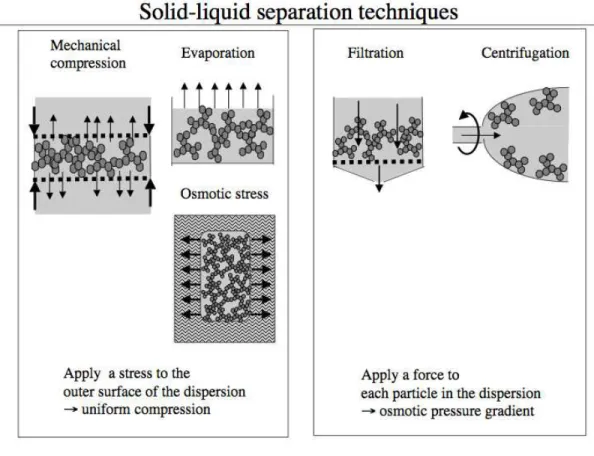
In each of these solid-liquid separation processes, the driving force is osmotic pressure. However, it is applied in different ways.
There is a family of experiments where pressure is applied to the boundaries of the system (the dispersion) in order to reduce its volume. In mechanical compression, the dispersion is placed in a pressure cell equipped with pistons that are permeable to the liquid phase [4]. Pressure is applied to the pistons and the network collapses while some liquid phase is forced out through the
membranes (Figure 1). In osmotic stress experiments, the dispersion is placed inside a dialysis bag, and immersed in a large volume of an aqueous polymer solution, of known osmotic pressure [15, 16]. The liquid is then extracted through its affinity for the external solution. Finally, in evaporation, the liquid is driven out from the outer surface through the chemical potential difference between the vapor and the liquid, and in this way the volume occupied by the dispersion is again reduced.
Then there is another family of experiments where a force is applied to each particle in the dispersion. For instance, in centrifugation, a force is applied to all particles [3, 4]. These forces are transmitted through the particle network, so that the osmotic pressure is highest at one end of the sediment and lowest at the other. The direction of the gradient depends on the sign of the density increment. As a result of this pressure, the sediment is compressed, and its height is seen to decrease (Figure 1). Similarly, in filtration, the flow of the continuous phase pushes the aggregates towards the membrane where they form a cake [17]. In the cake, each particle is submitted to a hydrodynamic force from the permeating liquid. These forces are transmitted through the network of interparticle contacts. As a result, the total force exerted on the aggregates located at the bottom of the cake is the sum of hydrodynamic forces exerted on all particles in the cake (Figure 1). Conversely, the force exerted on particles located at the top of the cake is the local hydrodynamic force only. Consequently there is an osmotic pressure gradient throughout the cake: the osmotic pressure is highest at the bottom of the cake, and it vanishes at the top.
Figure 1. Summary of methods used for solid-liquid separation. Left: methods where an osmotic pressure is applied to the boundaries of the system, and transmitted as a uniform pressure through the network of
particles. Right: methods where a force is applied to each particle, producing a pressure gradient throughout the dispersion.
Relation to thermodynamics
Regardless of their differences, all these methods rely on the application of an osmotic pressure (e.g. a difference in the chemical potential of the liquid within and outside the dispersion) to extract the liquid phase and reduce the volume occupied by the dispersion. In this way they resemble classical methods in thermodynamics, where a physical system responds with a change in its volume to an applied external pressure. Such thermodynamics processes are characterized by an equation of state, which can be followed in both directions (compression and decompression) and which depends only on the characteristics of the interacting atoms, molecules etc. It would be useful to know to what extent the compression behavior of a colloidal system can be described in the same terms. For this purpose, it is necessary to examine the behavior of model systems, where the characteristics of the particles may be controlled and their interactions may be varied systematically.
Model systems
A number of osmotic compression experiments have been performed already on model colloidal dispersions, using osmotic stress, mechanical compression or centrifugation [3, 4, 15-18]. The present paper reviews recent experiments in which aqueous dispersions of nanometric silica or clay particles were used as starting materials for the production of concentrated dispersions, aggregated suspensions, pastes (concentrated aggregated suspensions) and cakes (solid pastes). It also presents a reinterpretation of the data, using the cell model in the case of repelling particles, and a numerical model with spheres connected by springs in the case of aggregated suspensions. The choice of nanometric particles was important for two reasons. Firstly, they formed cakes that were not dense but highly compressible. Secondly, the relative positions of these particles could be determined by small angle neutron scattering (SANS). Therefore they were suitable for the study of the mechanisms by which cakes may rearrange their structures and collapse.
Repelling particles
Two types of aqueous silica dispersions were used. The main source was LUDOX HS 40 aqueous dispersions. These dispersions contain a high concentration (40 % wt) of globular silica particles. According to neutron scattering (see below), the number average diameter of the particles is 2a =15 nm, and the z-average is 24 nm. Each particle carries about 350 ionized SiO–
sites on its surface that are compensated by Na+ counterions located in a diffuse layer surrounding
the particle. The other silica dispersions were made in the laboratory though neutralization of sodium silicate by sulfuric acid. These particles had a mean size of 20 nm, and a narrow distribution of diameters around this value. Each particle carried about 200 ionized SiO– sites on
its surface, compensated by Na+ counterions located in a diffuse layer around the particle [16].
The other source of nanoparticles was LAPONITE XLG aqueous dispersions. These dispersions contain synthetic clay platelets; the thickness of the platelets is 2H = 1.35 nm and their diameter is 2R = 30 nm. Each face of the particle carries about 500 ionized sites, which are compensated by Na+ counterions located in a diffuse layer surrounding the particle [18].
Aggregated particles
Aggregation of the silica particles was promoted through addition of salt solutions (“flocculants”) to dilute silica dispersions (initial pH = 8). The first flocculant solution was a solution of divalent (Ca2+) cations. These cations accumulate on the silica surfaces, and therefore
suppress the ionic repulsions of the silica particles. At high surface charge densities, the correlations between ions located on neighboring surfaces create an attraction between these surfaces [19]. However, the silica particles also repel through hydration forces; in these conditions, only a small fraction of the collisions between silica particles cause them to aggregate [20, 21]. At longer times, the aggregates may be reinforced through direct Si-O-Si bonds between the silica surfaces [22].
The other flocculant solution was made by the hydrolysis of an AlCl3 solution. This hydrolysis
was produced by slow (5h) addition of NaOH at a ratio OH/Al = 2.2; the final pH was 4 ± 0.25 and the Al concentration was 0.1 M. In these conditions, it is known that the Al3+ cations react
with the added OH– to form polycations, of which the dominant ones are the [Al13 O4 (OH)24] 7+
polycations (hereafter abbreviated Al13
24h, and then added to the silica suspension; the final silica weight fraction was 1 % and the final Al concentration was 0.05M.
These polycations can react with the SiO– surface sites of the silica surfaces, and in this way
compensate the surface charge. At the isoelectric point, all the original counterions of the surface (Na+) have been displaced; consequently the repulsions caused by the overlap of electrical
double layers have vanished. The particles may then aggregate through electrical attractions of positive and negative surface charges.
The use of these two flocculant solutions made it possible to produce silica aggregates in which the particles were held either by relatively weak bonds (screening of surface charges by Ca2+) or
by very strong bonds (bridging by Al13 7+).
Results for dispersions of repelling particles
This section presents the compression behavior of dispersions in which the particles repel each other through the overlap of their ionic double layers. This is the case for silica dispersions and clay dispersions at high pH and low ionic strength.
Compression laws
The compression laws have been obtained by submitting the dispersions to a set of increasing osmotic pressures, and at each pressure measuring the volume occupied by the dispersion after osmotic and mechanical equilibria have been reached. For particles that interact through their diffuse layers of counterions, the resistance to compression reflects the free energy cost of the overlap of these layers that is caused by the compression.
Silica nanoparticles
The compression curves of two different silica dispersions are presented in Figure 2. The dispersions were made of silica particles of the same mean diameters, but they were synthesized in separate experiments. Also, the compression curves were obtained by different researchers, both using the osmotic stress technique [16, 24]. The good agreement of both sets of data implies that the measured compression curve is uniquely determined by the characteristics of the particles. It is also remarkable that these compression curves cover a range of 2 decades in silica volume fractions and 5 decades in pressures. Finally, some experiments have been performed in the reverse direction, reswelling the concentrated silica dispersions. It was found that the dispersions that were compressed up to a volume fraction φ = 0.5 could be reswelled in a reversible way. Consequently, the part of the compression that extends form the lowest volume fractions (φ = 0.02) up to φ = 0.5 is an equation of state of the silica dispersions.
Figure 2. Compression curves of aqueous dispersions of silica nanoparticles, obtained through the osmotic stress technique. (): data from Chang et al. [9]. (O): data from Persello [17]. Full line: calculation according to the cell model (equation 8).
Laponite clay particles
Aqueous laponite dispersions have been deswelled (i.e. compressed) and reswelled through different techniques. The results are presented in Figure 3. Equilibrium states of compression were obtained through the osmotic stress technique; the data obtained in two laboratories are in good agreement with each other, and also with the calculated ionic pressure of platelets [25-27]. Fast compression was achieved through centrifugation [28]: for a given pressure, these data are at a lower volume fraction than the osmotic pressure data, indicating that the dispersion had not reached equilibrium compression. Reswelling was obtained by centrifugation at high speed followed by centrifugation at a lower speed [28]: these data provide the true equilibrium equation of state of the dispersion. As in the case of the nanometric silica dispersion, such data demonstrate that the experiments measure the equation of state of the dispersion.
Figure 3. Deswelling and reswelling of aqueous Laponite dispersions. (Δ): deswelling by osmotic stress, data from Mourchid et al. [18, 19]. (): deswelling by osmotic stress, data from Lelièvre et al. [20]. (O): deswelling by centrifugation, data from Martin et al. [21]. (): Reswelling during centrifugation, data from Martin et al. [21]. Full line: calculated ionic pressure of parallel platelets with thickness 1 nm (equation 5).
Structures
Displacements of particles caused by compression
In a most general way, the resistance to any force applied to the dispersion originates from forces that oppose the relative displacements of particles. During compression, the particles are displaced and pushed closer together. In order to analyze the resistance to compression, it is necessary to have some information on these displacements. This can be obtained through scattering techniques, which measure a Fourier transform of the distribution of distances between particles.
We have used Small Angle Neutron Scattering, through experiments performed on the instrument D11 at the ILL. Compressed dispersions were recovered from compression cells, centrifugation tubes or dialysis bags and placed in scattering cells. In the case of centrifugation, where the forces applied to the particles produce a gradient of osmotic pressure, the content of the centrifugation tube was sliced to give a set of disks, each with a different osmotic pressure. In the
case of osmotic stress, the dialysis bags were also pulled out of the stressing solution and placed directly on the beam; the results were identical to those obtained using the other procedure.
Scattered intensities
Figure 4 presents the scattered intensities from dilute and concentrated silica dispersions. The intensities from the dilute dispersion match the scattering curve of independent polydisperse spheres. This was expected, since at low concentrations the silica particles do not interact with each other. In contrast, the scattered intensities from the concentrated dispersion are depressed at low Q values (corresponding to large distances) due to destructive interferences between rays scattered by distinct particles [29-32]. For a perfectly ordered concentrated dispersion, the intensity would be concentrated within a few Bragg peaks, with no scattering outside the peaks [29, 30]. The concentrated silica dispersion is not quite so well ordered: it has a scattering curve typical of liquid like order, with a broad peak at the average interparticle distance. According to this average distance, the number average diameter of the particles is 15 nm.
Figure 4. Scattering curves from silica dispersions. Horizontal scale: scattering vector Q, in Å-1. Vertical
scale: scattered intensities, normalized by the scattering of a 1 mm thick water sample. (): concentrated (40 % wt) dispersion. The depression of the intensity at low Q values results from a liquid-like ordering of silica particles, caused by interparticle repulsions. The peak position corresponds to the distance between planes of particles in this structure. According to this distance, the number average diameter of the particles is 15 nm. (Δ): dilute (1 % wt) dispersion. The fit (full line) corresponds to polydisperse non-interacting spheres; according to the curvature at low Q of this fit, the z-average diameter of the particles is 24 nm.
Structure factors
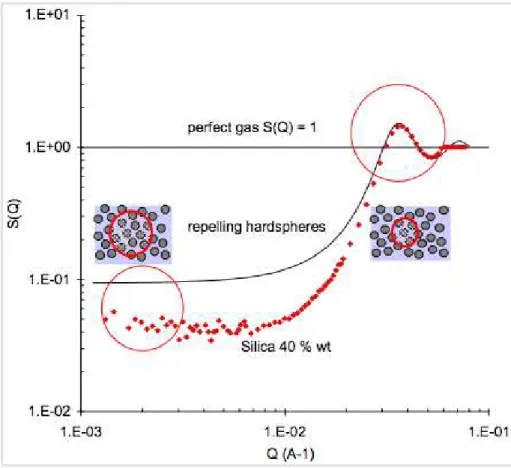
In concentrated dispersions, it is useful to compute the structure factor S(Q), which is the ratio of the intensity scattered by the dispersion with respect to that scattered by a single particle. This measures how the spatial distribution of the particles departs from the fully random distribution of a perfect gas. Specifically, at each Q value, S(Q) measures the magnitude of concentration fluctuations in the dispersion. For totally uncorrelated particles (the “perfect gas” case) S(Q) would be unity at all Q. For repelling particles, S(Q) is depressed at low Q values, because the long wavelength concentration fluctuations are suppressed. The limiting value of S(Q) at Q = 0 is the osmotic compressibility of the dispersion [9, 26]. Then, at Q values corresponding to nearest neighbor distances, S(Q) has a peak, because concentration fluctuations are quite strong at that scale (Figure 5).
Figure 5. Structure factor S(Q) of a concentrated (40 % wt silica dispersion). At each Q value, S(Q) measures the magnitude of concentration fluctuations in the dispersion. The depression of S(Q) at low Q expresses the fact that the dispersion is homogeneous at large scales: a volume of diameter 2π/Q contains the same number of particles regardless of its location in the dispersion. The depression is deeper than that of a dispersion of “hard spheres”, because the silica particles repel through diffuse ionic layers [31, 32].
In the case of dispersions of particles that repel as hard spheres, there exists an analytical expression of S(Q). This expression is obtained through the Percus-Yevick approximation to the Ornstein-Zernike integral equation, which is accurate at moderate volumes fractions (i.e. volume fraction that are below the fluid-solid transition). This structure factor is also shown in Figure 5: it has the same peak as the silica dispersions, indicating that the shell of nearest neighbors has a similar organization in both types of dispersions. On the other hand, the structure factor of the
silica dispersions is much lower at low Q values, because the long-range ionic repulsions suppress most of the long-range concentration fluctuations. Accurate approximations that yield S(Q) for dispersions with ionic repulsions have been given by Ottewill, Hayter, Ramsay and coworkers [30-33].
In the case of laponite platelets, the scattering pattern of concentrated dispersions consists of two diffraction spots located on either side of the beam. Accordingly, the organization of the particles is quite simple: they are parallel to each other and spaced at regular intervals along the normal to the platelets.
Cell model and the equation of state
Since the dispersions are ordered, they can be modeled as arrays of particles sitting in identical cells (Figure 6). In this model, the osmotic compression of the dispersion is equivalent to the compression of a single cell. The resistance to this compression originates from the gas of counterions that surround the particle in each cell; it may be calculated through the Poisson-Boltzmann cell model [15, 34].
Figure 6. Two-dimensional model of the dispersion as an array of cells, and resistance to compression of a single cell.
Laponite dispersions
Since the particles are parallel to each other and regularly spaced, it is sufficient to consider, as a cell, one half of the volume that separates two particles. The counterions of the particle are confined in this layer, which has a thickness h, determined by the laponite volume fraction φ and by the particle half thickness H through:
φ
=
H
h
+ H
(1)For concentrated dispersions (0.1 < φ < 0.4), this yields half separations that are in the range 1 nm < h < 6 nm. This range must be compared with the two characteristic lengths that characterize the variations of the electrical potential in the vicinity of charged surfaces (λ) and in the aqueous solution away from the surfaces (κ-1) [35-37]. The Gouy-Chapman length λ that gives the scale of
λ
=
2
kT
ε
0ε
rσ
e
2 (2)The Gouy-Chapman length for Laponite surfaces (σ = 0,7 charge /nm2) is λ = 0,32 nm.
Consequently, h >> λ, and therefore most counterions are condensed on the particle surfaces. On the other hand, the screening length κ-1 that gives the scale of variations of the electric potential
due to background salt is:
κ
−1= 4
π
l
Bz
j j∑
c
j
−1/ 2(3)
where zj and cj are the charge number and concentration of each ionic species and lB is the
Bjerrum length defined as:
l
B=
e
2
4
π ε
0
ε
rkT
(4)
For the laponite dispersions, this yields κ-1 = 4 nm, and therefore h < κ-1 over most of the
concentrated range. In these conditions, passive salt is excluded from the interstitial solution that separates neighboring platelets, but the counterions are not uniformly distributed within this interstitial solution. Instead, they accumulate near the charged surfaces, giving a pressure that is independent of the surface charge density and decays as the inverse square of separation [35-37]:
Π =
π
2
kT
l
B1
2h
2 (5)The pressures calculated according to this equation have been plotted on Figure 3. It can be seen that they match exactly the osmotic pressures that have been measured through reswelling experiments, which are believed to be true equilibrium values. Since there are no adjustable parameters in equation (5), the agreement can be considered as excellent.
Silica dispersions
In this case, the cell can be approximated as a spherical volume surrounding the particle. Since the particle surfaces have a high surface charge density, their counterions are not uniformly distributed within this volume. Instead, they accumulate near the surfaces, and compensate most of the surface charge. Let Z be the number of charges carried by the surface of a particle, Z1 the
number of condensed counterions, and Zeff = Z – Z1 the number of counterions that are actually
dispersed in the cell. This effective charge can be evaluated using the prescription of Trizac et al [37]
Z
eff=
a
l
B(
1 +
κ
a
)
(6)The cell radius Rc must also be compared with the characteristic length that characterizes the
variations of the electrical potential in the aqueous solution away from the surfaces (κ-1). In the
case of the silica dispersions, Rc is related to particle radius a and to volume fraction φ by:
R
c= a
φ
−1 / 3 (7)For the silica dispersions prepared through osmotic stress, this yields 10 nm < Rc < 75 nm. The
screening length of these dispersions is κ-1 = 10 nm, hence κ-1 < R
c over the whole range of
volume fractions, which means that the added salt is effective in screening the surface charges. In these conditions, the osmotic pressure of the dispersion is inversely proportional to the square of the volume v of the cell:
Π = kT n
P+
Z
eff2v
21
n
s
(8)where nP is the concentration of particles, and ns the bulk concentration of cations from the added
salt. The pressures calculated according to this equation have been plotted on Figure 2. It can be seen that they match exactly the osmotic pressures that have been measured through osmotic stress experiments, which are believed to be true equilibrium values. Since there are no adjustable parameters in equation (8), the agreement can be considered as excellent. Note that for these globular particles, as well as for platelets (equation 5), the pressure varies as the inverse square volume of the interstitial solution that separates particles.
Conclusions for repelling particles
At this stage we may conclude that dispersions of repelling particles have a unique compression behavior, which only depends on the characteristics of the particles. This is the equation of state of the dispersion. Accordingly, the compression behavior of dispersions of repelling particles can be described according to the laws of thermodynamics.
However most applications of colloidal dispersions involve particles that stick to each other rather than repel. In ceramic pastes the compressed cake must have a sufficient cohesion to retain its shape after molding and until the firing stage. In the deposition of paper coatings, and in the conditioning of sludge, the cake must retain a sufficient porosity to ensure fast drainage of the liquid that it contains. Thus, it is useful to examine whether the compression behavior of such dispersions can also be described by something that resembles an equation of state.
Results for dispersions of aggregated particles
Dispersions of aggregated particles also oppose a strong resistance to osmotic compression, even though the particles do not repel each other. This resistance originates from the mechanical rigidity of the aggregates. The pressures that are needed to reach substantial volume fractions can be quite high, especially in the case of nanometric particles. Some examples from previous work on a variety of mineral dispersions are given below.
Compression laws
Previous work
Zukoski and coworkers made aggregated dispersions of mineral particles by bringing the pH of the aqueous phase to the isoelectric point (i.e.p.) of the particles, and performed compression experiments on these pastes [4]. They compared the effects of different compression techniques: osmotic stress (dialysis), centrifugation and mechanical compression. For each dispersion, the compression curves from different techniques were identical, demonstrating that the compression resistance was a material property, uniquely determined by the characteristics of the dispersion. When particles of different sizes were compared, the resistance was much higher for the smaller particles: with the same applied pressure (105 Pa or 1 atm), the dispersions of larger particles
(139 nm) reached a volume fraction of about 0.13, whereas smaller ones (57 nm) reached only 0.1, and the smallest ones (8 nm) remained at 0.06. For the smallest particles, these resistances are quite high (compare with the pressures of non aggregated dispersions, shown in Figure 2). Lange and coworkers compared the mechanical properties of dispersions of particles that were aggregated in different ways [38, 39]. They found an enormous difference between a dispersion that was flocculated by adjusting the solution pH to the i.e.p. of the particles, as in Zukoskis’s work, and a dispersion that was coagulated by the addition of salt. The latter yielded much easier to applied stress than the former. Therefore the strength of interparticle forces is the most important factor determining the mechanical resistance of dispersions of aggregated particles. From such experiments, it may be concluded that the mechanical properties of dispersion of aggregated particles are governed by the strength of interparticle forces, and by characteristics of the individual particles such as shape and size.
Silica nanoparticles aggregated by Ca2+ and by Al13 7+
In the present work, aqueous dispersions of silica nanoparticles were aggregated at high pH (far from the i.e.p. of the particles) by the addition of divalent cations (Ca2+) or polycations (Al
13 7+).
These aggregated dispersions were made mainly for the purpose of studying the structure, porosity and connectivity of the compressed cakes. However, some compression resistances were also measured. They were on the order of 105 Pa for dispersions that were held together by
strong forces (at φ = 0.125), i.e. of the same order of magnitude as those measured by Zukoski and coworkers for particles of comparable sizes.
Structures
Displacements of particles caused by compression
When dispersions of aggregated particles are submitted to osmotic compression, the aggregates build a continuous network (Figure 7). Any deformation of this network requires some shifts of interparticle contacts, and is opposed by cohesive forces acting on these contacts. If the applied osmotic pressure is lower than the corresponding yield stress, the cake is not compressed. However, if the applied pressure exceeds this threshold, the cake yields and shrinks to a smaller volume, releasing some of the liquid phase. This compression is accomplished through deformation of the aggregates and partial collapse of their voids. These relative displacements of the particles can be observed through Small Angle Neutron Scattering.
Figure 7. The resistance to compression of a network of aggregated particles originates from forces exerted at the points of contact of neighboring particles. These forces are non-central. The contacts may also be disrupted, leading to dissipation of energy and irreversible deformation of the network.
Scattered intensities
Before compression, the structures of the aggregates in silica suspensions are characteristic of large bushy, fractal objects [31, 32, 40, 41 ]. Indeed, the scattering curves of both suspensions show high intensities at low Q values, demonstrating the presence of large aggregates, and a power law decay (exponent – 2.15), reflecting the fractal structure of the aggregates (Figure 8). After compression, the scattered intensities are strongly depressed (they are 10 to 100 times weaker), indicating that the cakes are much more homogeneous than the suspensions. Qualitatively, it is easy to understand that this depression is caused by the collapse of the voids that separate the aggregates. Quantitatively, it is necessary to calculate the structure factors in order to analyze this effect.
Figure 8. Upper curves: scattering from aggregated suspensions. (Δ): silica particles aggregated by addition of Al137+ polycations. (): silica particles aggregated by addition of Ca2+. The power-law decay
plots, is –2.15. The absence of a peak at the distance of nearest neighbors indicates that each silica particle has a low number of nearest neighbors (definitely not larger than 4). Lower curves: scattering from compressed cakes. (o): silica particles aggregated by addition of Al137+ polycations. (): silica particles
aggregated by addition of Ca2+. The depression of the intensity is caused by the collapse of the voids that
separate the aggregates.
Structure factors
The structure factors of aggregated dispersions are defined in the same way as those of repelling dispersions: at each Q value, S(Q) measures the magnitude of concentration fluctuations in the dispersion. They are, however, strikingly different: S(Q) has a very high value (S(Q) = 100) at low Q values (Q = 0.001 Å–1), and then decays towards S(Q) = 1 at high Q values (Figure 9). This
is in contrast with the depression of S(Q) at low Q that was observed in dispersions of repelling particles (compare with Figure 5).
Figure 9. Structure factor of a suspension containing silica nanoparticles aggregated by addition of Al137+
polycations. The power-law decay at low Q reflects the fractal structure of the aggregates. The absence of a peak at the distance of nearest neighbors (high Q) indicates that each silica particle has a low number of nearest neighbors (3 to 4).
The high values of S(Q) at low Q result from concentration fluctuations produced by the presence of aggregates in the suspension (a given volume of suspension may contain a whole aggregate, or no particles at all). The decay that follows reflects the internal structure of the aggregates: the exponent (– 2.15) indicates that the number of particles included in a volume of radius R around a given particle scales as N(R) = C R2.15. Accordingly, the structure of these aggregates is mostly
full of voids – since a dense structure would be characterized by N(R) = C R3.
At high Q values, corresponding to distances between neighboring particles, the structure factor of the aggregates simply goes to unity instead of having a peak as was the case for the ordered
dispersions of repelling particles (compare with Figure 5). This feature indicates that the coordination number of the aggregated particles is low, typically 3-4, as is commonly the case in bushy aggregates [42]. Indeed, if each particle had a complete coordination shell (8 to 12 neighbors), there would be a strong peak at the nearest neighbor distance, as in concentrated dispersions and colloidal crystals [30-32].
From this structure factor, it may be concluded that the aggregated silica suspensions are made of large aggregates which contain voids at all scales – from nearest neighbor distances to scales that are at least 100 times larger. The spatial distribution of these voids is self-similar (fractal dimension df = 2.15). This is exactly the type of structure that is produced by aggregation of
clusters, in the regime where only a small fraction of all the collisions are successful and lead to permanent sticking (RLCA).
The structure factors of the compressed dispersions are shown in Figure 10. They show a substantial depression of S(Q) at low Q values, and no changes at high Q. As the applied pressure is increased, the depression becomes deeper and broader. Now, a depression of S(Q) indicates that concentration fluctuations with the relevant wavelengths have been suppressed, i.e. the concentration of particles has become more uniform at those scales [16, 33]. Since the aggregated dispersion has been compressed, these regions of uniform density must result from the collapse of voids that separate the aggregates. It is possible to evaluate the characteristics of these regions from the depth and width of the depression in S(Q). As shown in figure 10, the depression produces values of S(Q) that are below unity when the applied pressure reaches 2 atm. This is the minimal pressure that is required to force interpenetration or compression of the outer regions of the aggregates. The width of the depression increases with applied pressure; at the highest pressures, it extends down to Q values that correspond to distances on the order of 20 particle diameters: this is the typical dimension of these regions of uniform particle density.
Figure 10. Structure factors from the suspension aggregated by Al137+ () and from cakes made by
compression in the oedometer cell (pressures indicated on the graphs). The depression of S(Q) in the intermediate range of Q reflects the loss of pores with diameters corresponding to these Q values.
There are also interesting features on either side of the depression. At the lowest Q values (Q = 1 x 10⁻³ Å–1 and below), the cakes still scatter large intensities, indicating the presence of strong
heterogeneities in the concentration of particles. A priori, these concentration fluctuations could be either e.g. macropores (concentration lower than the average) or grains (concentration higher than the average. Scattering does not discriminate between both possibilities (the intensity is proportional to the square of the fluctuation in scattering density). However, it is obvious that large macropores would have collapsed under the effect of the applied pressure. Indeed, the permeability of the cakes is lower than that of a random array of spheres at the same volume fraction, rather than higher, as would be the case if the cake contained macropores. Hence, the large-scale concentration fluctuations that have remained in the cakes must be dense grains, lumps or films originating from the collapse of weaker structures.
The correspondence with a structure made of dense lumps dispersed in a uniform matrix can be examined quantitatively by using the structure factor from an equilibrium hard sphere liquid, which could approximate the matrix, and adding a contribution that represents the scattering from the lumps. Indeed, at volume fractions that match those of the cakes, hard sphere liquids have theoretical structure factor that is depressed low Q, due to the suppression of long wave length fluctuations by interparticle repulsions (see Fig 5). On the other hand, the scattering from the frozen concentration fluctuations (dense lumps) can be represented by a power-law decay at low Q. In this way, the experimental S(Q) of cakes compressed at 2 atm (φ = 0.1) can be reproduced by the linear combination of a Q–2 decay and the S(Q) for hard spheres at the same volume fraction. Similarly, the S(Q) of cakes compressed at 4 atm (φ = 0.23) is matched by the linear combination of a Q-4 decay and the theoretical structure factor for the hard sphere liquid at
Figure 11. Structure factors from the suspension aggregated by Al137+ () and from the cakes made by
compression of this suspension in the oedometer cell. (+): Cake compressed at 1 atm; fit by the structure factor of hard spheres at volume fraction φ = 0.1 (full line) and by the same structure factor with an additional Q–2 contribution from the cores of the aggregates (dashed line). (): Cake compressed at 4
atm; fit by the structure factor of hard spheres at volume fraction φ = 0.14 (full line) and by the same structure factor with an additional Q–4 contribution from the cores of the aggregates (dashed line).
Finally, at the highest Q values, corresponding to distances between neighboring particles, the structure factor of the compressed dispersions remains close to that of the original aggregates. The absence of a peak at this position indicates that the particles have retained their original coordination instead of acquiring a complete coordination shell. Hence the collapse of the cake results from small relative motions of the particles that leave the local coordination unchanged. Taken together, these features give a fairly precise image of what happened during compression of the aggregated silica dispersions. The particles had very small relative displacements that led to the large-scale changes in the structure of the cake. This structure was made of dense regions dispersed in a less dense matrix. As the pressure was increased, the dense regions first retained a bushy structure (fractal dimension 2), and then became dense lumps (fractal dimension 3). Meanwhile, the concentration in the matrix became more uniform; at the higher pressures, the average dimension of the regions of uniform concentration reached 20 particle diameters.
Comparison of different aggregated dispersions
With this detailed picture, it becomes possible to determine whether different aggregated dispersions go through the same structural stages or through different stages during the compression process. For this purpose, dispersions of silica particles that have been aggregated with respectively Al13
Figure 12. Structures factors from the suspension aggregated by Ca2+ () and from the cakes made by
compression of this suspension in the filtration cell (pressures indicated on the graphs). The very strong depression of S(Q) in the intermediate range of Q reflects the collapse of all pores with diameters corresponding to these Q values.
With the Ca2+ cakes, stronger compressions are obtained at much lower pressures; however, the set of curves appears similar to those obtained with the Al13
7+ cakes. If both dispersions go
through the same structural stages during compression, then for structure of one set of cakes there must be a corresponding cake in the other set with an identical structure factor. This comparison is shown in Figure 13, where the structure factors obtained at 2 atm for the Al13
7+
cakes and at 0.2 atm for the Ca2+ cakes appear to match exactly. Accordingly, both dispersions go through the same structural stages, the only difference being in the scales of pressures that are required to reach these stages.
Figure 13. Comparison of the structure factors of dispersions flocculated with Al (Δ) and with Ca (), and of the cakes made at pressures that give matching structures: Π = 2 atm for Al (O) and 0.2 atm for Ca ().
Since different aggregated dispersions go through the same structural stages during the compression process, it may be that this compression behavior is general for all dispersions of aggregated spherical particles. This general behavior may not be recovered from a classical thermodynamic analysis, since the dispersions are in a “frozen” state rather than in a state at thermodynamic equilibrium. On the other hand, a numerical model with a minimal set of ingredients may be able to reproduce this general behavior. The next section presents a search for such a model.
Numerical model
The resistance to compression of a network of aggregated particles originates from forces exerted at the points of contact of neighboring particles. These forces are non-central. Also, the effects of these forces on the mechanical resistance of the whole network depend on the connectivity of the network (which particles ate bound to which ones) and on its structure (which particles are next to which other ones). This makes a calculation of the resistance more difficult than in the case of repelling particles, where it was sufficient to consider a single cell containing one particle. Indeed, in the case of particle networks, the resistance will depend on the initial structure of the network. A further difficulty lies in the fact that the contacts may be disrupted, leading to dissipation of energy and irreversible deformation of the network; consequently the resistance may also depend on the history of compression. Thus, the prediction of the compression resistance of a network of aggregated particles is a formidable problem. Given these difficulties, it may be appropriate to examine the behaviors that can be obtained through numerical experiments on simplified aggregates.
Model
A simple numerical model has been devised recently [43]. It consists of a 3-dimensional system of spheres with a stiff hard-core repulsion and with pins on their surfaces, to which harmonic springs may be connected (Figure 14). The number of pins on the surface of a sphere has to be large enough that two neighboring spheres are connected by a large number of springs, producing non-central forces that give a resistance to bending. Springs are automatically created by the algorithm if two pins from distinct spheres come within a minimal distance la; they are
automatically destroyed if this distance is stretched beyond a maximal length ld; their length at
rest is l0, which is conveniently set at l0 = la (the dimer and higher aggregates are created with the
spheres at their equilibrium distance).
Figure 14. “Spheres and springs” model of the colloidal aggregates. Non-central forces between the particles in the aggregates are produced by springs attached to pins located on the particle surfaces.
In order to generate a numerical “paste”, a RLCA process us used to create aggregates of these spheres, with fractal dimension df = 2. These aggregates are then sedimented in a box where they
connect to each other, forming the paste. The box has periodic boundary conditions in the y and z directions, so that when a particle leaves the box in one of these directions it reenters on the opposite side. In the x direction, however, the boundaries are impenetrable walls. Pressure is applied to the upper x boundary, as a force applied to the highest particles. Since the resistance against this force originates from the springs, the unit of force is the spring constant multiplied by the length of a spring at rest.
Algorithm
A compression step is performed as follows: when the external force Fext is applied to the top
particles, they are displaced by an amount ∂x = α Fext. The rest of the system is then relaxed
according to the forces transmitted by the springs, i.e. the other particles are displaced by ∂x = α Fint. This relaxation step is repeated many times in order to ensure proper propagation of stresses
throughout the aggregates. Numerical simulations of the deformation of simple aggregates (rod-like aggregates) demonstrated that complete propagation of stress was achieved with a cycle containing 5000 internal relaxation steps. This full transmission of stresses corresponds to the quasi-static deformation of the system. Alternatively, the choice of incomplete propagation of the stresses would result in accumulation of particles on the impenetrable boundaries. This could mimic violent deformations of the structure.
The final volume of the box at the end of a compression step is taken as measure of the volume fraction of the dispersion in a quasi-static mechanical equilibrium condition. Another compression step is then performed, and in this way whole compression curve is recovered as a succession of quasi-static steps at mechanical equilibrium. Some pictures of the box at intermediate stages of compression are shown in Figure 15. Note that these pictures are projection images of the box onto a plane that is parallel to the compression direction; hence, the projection images of many particles do overlap, and the aggregates do appear denser than they really are. Nevertheless, these pictures are useful to verify that the aggregated dispersion has indeed been uniformly compressed.
Figure 15. Projection images of the aggregated dispersion, taken at various stages of compression. The original locations of the impenetrable walls are indicated as dashed vertical lines. The volume fractions of particles in the box are respectively 0.06 (left), 0.3 (middle) and 0.63 (right, full compression).
Quasi-static compression curves
Many aggregated dispersions have been generated, and for each one a compression experiment has been performed as a succession of quasi-static equilibria at increasing applied pressures. Remarkably, the compression curves obtained for aggregates generated with different initial conditions but identical spring parameters are the same. Consequently, the compression behavior of these aggregated dispersions is uniquely determined by interparticle forces, as was found in the real systems (see above).
When interparticle forces (spring parameters) are changed, the compression curves are changed as well (Figure 16). The parameters that characterize a spring are the spring constant, equilibrium length and maximum stretching length. The first two parameters determine the unit of force, so that their values can be used to match the scale of applied pressures to those of the real system.
The maximum stretching length ld/l0 (or stretching energy Ed = (ld/l0) 2
) determines how the network of springs responds to stress. At very high values of ld/l0 (or Ed), the springs do not break
at all, and the network has a purely elastic response to the applied stress. In this regime, the pressure rises a power law of the volume fraction with a high exponent (4.4). This power law matches theoretical predictions [44] and also experimental compression data obtained on dispersions of mineral particles [4]. At intermediate values of ld/l0 (or Ed), the springs do break
when the pressure exceeds a certain threshold, and the network has a plastic response to the applied stress. In this regime, the pressure also rises a power law of the volume fraction, but with a much lower exponent (1.7). This power law has been observed in silica dispersions that have been aggregated by multivalent cations and compressed through osmotic stress [45]. Finally, at low values of ld/l0 (or Ed), the springs break quite readily, and the network is very fragile: as soon
as pressure is applied, many springs are broken and the system is unable to create a network that would support the applied pressure; hence it collapses to maximum density (here about 0.64).
Figure 16. Compression curves of model aggregates, obtained through numerical simulation. The steep rise of pressure (Π ≈ φ4.4) in the upper set of data (Δ, bond rupture energy E
d> 360) corresponds to an
elastic response of the particle network; the slower power law (Π ≈ φ1.7) in the intermediate sets of data (♦,
Ed = 9, and o, Ed = 4) to a plastic respond where bonds are continuously broken and created; the lower
sets (full lines, Ed = 0.04) to a fragile network that is unable to withstand any applied pressure.
A remarkable feature of these numerical simulations is that they show only two well-defined regimes (elastic and plastic response), and within each one the compression curves are similar. For instance, all the compression curves obtained in the plastic regime can be made to overlap through a shift in pressure scales (Figure 17). Some theoretical arguments can be constructed to explain why the compression response of aggregated dispersions follows such simple laws [43]. It is also a feature of the experimental compression laws that the exponents seem to be either
close to 4.4 or to 1.7 [4, 45]: thus, the numerical model provides an explanation for these two behaviors, in terms of elastic vs. plastic deformation
Figure 17. Master curve obtained for the plastic response of numerical dispersions. The individual sets data correspond to dispersions with the same spring parameters (1<Ed<9) but different aggregates, or with
different spring parameters.
The numerical model also reproduces some structural features of the compressed cakes. Indeed, the structure factor S(Q) of the numerical array of spheres shows a depression at intermediate Q values, that matches the corresponding depression in the S(Q) of the aggregated silica cakes (Figure 18). Although the precision of the numerical S(Q) is poor, due to the finite size of the box, this depression appears to reflects the presence of regions of nearly uniform concentration, as in the silica cakes. Conversely, the numerical model makes it possible to visualize the dense regions, or, more interestingly, the “active” regions in which some spheres have been brought into direct contact with each other by the applied stress. It is found that these “active” spheres are gathered in dense lumps that are separated by the less dense “matrix”. Thus, the numerical model brings an explanation of the respective functions of two types of regions that were found in the structures of the aggregated silica cakes. The dense regions (i.e. the “lumps” that give the steep decay of S(Q) at low Q) form a skeleton that carries most of the load. The less dense regions (i.e. the “matrix” that gives the depression of S(Q) at intermediate Q values) uses the spaces that lie between “columns” of this skeleton, and generate weak forces that maintain the lateral stability of these columns [43].
Figure 18. Comparison of the structure factor of numerical aggregates with that of silica cakes. (o), numerical aggregates compressed to a volume fraction φ = 0.175. silica dispersions aggregated by Al137+ polycations and compressed to φ = 0.23 (4 atm). In both sets of data, the depression at intermediate
Q values originates from regions of the cake that have a low, nearly uniform concentration. The steep decay at very low Q originates from dense regions (lumps) that carry most of the applied pressure. The oscillations at high Q reflect the average coordination shell of a particle, which is more regular in the numerical aggregates than in the actual dispersion, due to polydispersity and non-sphericity of the silica particles.
Conclusions
Aggregated and non-aggregated dispersions resist osmotic compression through entirely different mechanisms.
In non-aggregated dispersions, made of particles that repel through the osmotic pressure of their ionic layers, all particles take equal part in the resistance to compression. Consequently, the resistance of the dispersion equals the resistance of a single cell made of one particles with its counterions. This resistance is thermodynamic in its nature: at each applied pressure, the volume of the cell is determined by the equilibrium of applied pressure with the osmotic pressure of the ionic layers. Changes in pressure may lead to either compression or expansion of the cell. These changes follow an equation of state in which the pressure varies as square of volume fraction (or rather, as the inverse square of the volume of interstitial solution within the cell).
In aggregated dispersions, a small fraction of the particles makes a dense skeleton that bears most of the load, while the others form a less dense matrix that fills the spaces between the columns of the skeleton and contributes to the lateral stability of these columns. This resistance is non-thermodynamic in its nature: at each increment in pressure, the skeleton undergoes plastic deformation until its yield stress matches the applied forces. This leads to a (non reversible) compression law, in which the pressure varies as a power law of volume fraction, with an exponent (φ1.7) that is similar to the exponent for repelling particles (φ2).
For practical applications, it is often necessary to make the resistance as low as possible. This leads to the choice of dispersions that are either weakly repulsive or weakly aggregated. In this work, the choice was nanometric silica particles that either repelled through layers of monovalent cations or aggregated through addition of multivalent cations. Surprisingly, both choices lead to osmotic resistances that are of the same order of magnitude, even though the mechanisms of resistance are entirely different, and the interparticle forces do not have the same strengths.
This coincidence may be actually caused by a compensation between the strengths of interparticle forces, and the numbers of particles that develop such forces. For non-aggregated dispersions, there is a limit to how weak the interparticle forces can be. Indeed, if the particles are quite small, low ionic pressures lead to aggregation of the particles [46]. On the other hand, for aggregated dispersions, the interparticle forces are much stronger, but, as shown in this work, the skeleton that bears the load contains only a small fraction of all the particles. Given these constraints, weakly aggregated and non-aggregated dispersions have similar resistances to solid-liquid separation, and this resistance is quite substantial in the case of nanometric particles.
This absence of an easy path to compression may have serious consequences for the production of nanometric ceramics. Indeed, the sintering processes of mineral dispersions require volume fractions that are at least 0.5 in order to produce a 3-dimensional solid that is free of voids. There may be no easy way to reach such high volume fractions with nanometric dispersions that are stabilized through ionic forces only. Thus, it may be useful to look for other methods of stabilization [46].
References
1 B.J. Kellett, F.F. Lange. J. Am. Ceram. Soc. 72, 725 (1989) and ibid. 72, 735 (1989) 2 F.F. Lange. J. Am. Ceram. Soc. 72, 3 (1989)
3 L. Bergström, C.H. Schilling, I.A. Aksay. J. Amer. Ceram. Soc. 75, 3305 (1992) 4 K.T. Miller, R. Melant, C.F. Zukoski. J. Am. Ceram. Soc. 79, 2545 (1996) 5 J. Persello. WOFR 0001286 (12 - 05 - 2000) FR 2794115 (12 - 05 - 1999)
6 R.L. Nelson, J.D.F. Ramsay, J.L. Woodhead, J.A. Cairns, J.A.A. Crossley. Thin Solid
Films 88, 329 (1981)
7 C.Baruffaldi, S. Cattarin, M. Musiani, B. Vercelli, A. Foissy, J. Persello. International Society of Electrochemistry 53rd Annual Meeting 2002.
8 K. Putkisto, J. Maijamla, J. Grön, M. Rigdhal. Nordic pulp Paper Res. J. 18, 226 (2003) 9 D.J. Lee, C.H. Wang. Wat. Res. 34, 1 (2000)
10 E.J. La Heu, P.J.A.M. Kerkhof, A.J.M. Herwijn, W.J. Coumans. Wat. Res. 30, 697 (1996) 11 C.C. Wu, J.J. Wu, R.Y. Huang. Colloids Surfaces A 221, 141 (2003)
12 N. Böhm, W.-M. Kulicke. Colloid Polym. Sci. 275, 73 (1997) 13 G.H. Meeten. Colloids Surfaces 82, 77 (1994)
14 J. D. Sherwood, G.H. Meeten. J. Pet. Sci. Eng. 18, 73 (1997)
15 C. Bonnet-Gonnet, L. Belloni, B. Cabane. Langmuir 10, 4012 (1994)
16 J. Chang, P. Lesieur, M. Delsanti, L. Belloni, C. Bonnet-Gonnet, B. Cabane. J. Phys.
Chem. 99, 15993 (1995)
17 D. Antelmi, B. Cabane, M. Meireles, P. Aimar. Langmuir 17, 7137 (2001)
18 P. Levitz, A. Delville, E. Lecolier, A. Mourchid. Progr. Colloid Polym. Sci. 118, 290 (2001)
19 Bo Jönsson, H. Wennerström, A. Nonat, B. Cabane. Langmuir 20, 6702 (2004) 20 L.H. Allen, E. Matijevic. J. Colloid Interface Sci. 31, 287 (1969)
21 J. Depasse, A. Watillon. J. Colloid Interface Sci. 33, 430 (1970) 22 J. Depasse. J. Colloid Interface Sci. 194, 260 (1997)
23 B.S. Lartiges, J.Y. Bottero, L.S. Derrendinger, B. Humbert, P. Tekely, H. Suty. Langmuir
13, 147 (1997)
24 J. Persello. Private communication
25 A. Mourchid, A. Delville, J. Lambard, E. Lecolier, P. Levitz. Langmuir 11, 1942 (1995) 26 A. Mourchid, E. Lecolier, H. Van Damme, P. Levitz. Langmuir 14, 4718 (1998)
27 V. Lelièvre, private communication
28 C. Martin Gros d’Aillon, thèse, Institut National Polytechnique de Grenoble, 2002 29 A. Guinier, G. Fournet. Small Angle Scattering of X-rays. Wiley, New York (1955)
30 D.J. Cebula, J.W. Goodwin, G.C. Jeffrey, R.H. Ottewill, A. Patentich, R.A. Richardson.
Faraday Discuss. Chem. Soc. 76, 37 (1983)
31 J.D.F. Ramsay, M. Scanlon. Colloids Surfaces 18, 207 (1986) 32 J.D.F. Ramsay. Chem. Soc. Rev. 15, 335 (1986)
33 J.B. Hayter, Faraday Discuss. Chem. Soc. 76, 7 (1983) 34 W.R. Bowen, F. Jenner. Chem. Eng. Sci. 50, 1707 (1995)
35 D.F. Evans, H. Wennerström, The Colloidal Domain. Wiley, New York (1994).
36 B. Cabane, S. Henon. Liquides: solutions, dispersions, emulsions, gels. Belin, Paris 2003 37 E. Trizac, L. Bocquet, M. Aubouy. Phys. Rev. Lett. 89, 248301-1 (2002)
38 B.V. Velamakanni, J.C. Chang, F.F. Lange, D.S. Pearson. Langmuir 6, 1323 (1990) 39 M. Colic, G.V. Franks, M.L. Fisher, F.F. Lange. Langmuir 13, 3129 (1997)
40 D.W. Schaefer, J.E. Martin, P. Wiltzius, D.S. Cannell. Phys. Rev. Lett. 52, 2371 (1984) 41 C. Aubert, D.S. Cannell. Phys. Rev. Lett. 56, 738 (1986)
42 R. Jullien, R. Botet. Aggregates and fractal aggregates. World Scientific, Singapore 1987 43 R. Botet, B. Cabane. Phys. Rev. E. 70, 031403 (2004)
44 W.D. Brown, R.C. Ball, J. Phys. A 18, L517 (1985) 45 C. Parneix, private comunication