ON THE MITIGATION OF LATE STAGE REDESIGN IN MECHATRONICS USING INTEGRATED APPROACHES
UGO CHOUINARD
DÉPARTEMENT DE GÉNIE MÉCANIQUE ÉCOLE POLYTECHNIQUE DE MONTRÉAL
THÈSE PRÉSENTÉE EN VUE DE L’OBTENTION DU DIPLÔME DE PHILOSOPHIAE DOCTOR
(GÉNIE MÉCANIQUE) MAI 2019
ÉCOLE POLYTECHNIQUE DE MONTRÉAL
Cette thèse intitulée :
ON THE MITIGATION OF LATE STAGE REDESIGN IN MECHATRONICS USING INTEGRATED APPROACHES
présentée par : CHOUINARD Ugo
en vue de l’obtention du diplôme de : Philosophiae Doctor a été dûment acceptée par le jury d’examen constitué de :
M. BALAZINSKI Marek, Docteur ès Science, président
M. ACHICHE Sofiane, Ph. D., membre et directeur de recherche M. BARON Luc, Ph. D., membre et codirecteur de recherche M. ZENG Yong, Ph. D., membre
DEDICATION
ACKNOWLEDGEMENTS
If I could have an analogy for my PhD, I would compare it to a good burger. As any burger needs a patty and a bun, a successful PhD needs good supervisors. I would thus like to thank first and foremost my supervisor, Prof. Sofiane Achiche, who helped me and guided me throughout the span of my PhD, who gave me opportunities to expand my experience as a PhD student by helping me apply to research internships. I would also like to thank Prof. Luc Baron, my co-supervisor, for giving me the opportunity to be part of this project.
I remember meeting both Prof. Achiche and Prof. Baron before starting this PhD project, coming fresh out of my undergraduate degree. They trusted me from the beginning even though I was skipping the master’s degree. I will be forever grateful that they believed I was able to carry out this research project, while giving me the freedom to research on a subject that interested me. Moreover, one always has the option to order extras on a burger, such as cheese and bacon. I was thus lucky to get these extras during my PhD as I had the opportunity to carry out part of my PhD in other countries, and thus greatly enhancing my burger, sorry I meant PhD, experience. I would thus like to express my gratitude to Profs. Christian Duriez, Tim McAloone and Daniela Pigosso that welcomed me in their teams for a few months.
Although we should have a very good burger by now, it still needs a bit of personalisation, such as tomatoes, lettuce and pickles. Hence, I would like to thank my colleagues in the COSIM Lab at Polytechnique for the fruitful discussions and the good times spent there. In between the card games during lunches or the serious talks about the research project, they kept me motivated to finish the PhD. I would also like to thank the wonderful people I met when doing research abroad.
The last but not least, a burger would not be possible without Ketchup. Ketchup is particular, as it is there no matter what you eat, and you always know that you can count on it. I would finally like to thank my parents and my brothers for being there and supporting me when needed.
RÉSUMÉ
Les systèmes mécatronique combinent des éléments issus du génie mécanique, électrique, contrôle et logiciel. Due à la nature multi-domaine de ces systèmes, il est nécessaire de s’assurer d’un processus de conception optimal afin de réduire le temps et le cout de développement. De ce fait, cette thèse s’intéresse aux boucles de re-conception tard durant le processus de développement. Ces boucles peuvent être causé entre autres par des interactions négatives qui affectent la performance et l’intégration des composantes et sous-systèmes et l’incertitude dans les paramètres du système.
Premièrement, cette thèse propose une nouvelle méthode de modélisation qui permet d’identifier et d’évaluer les dépendances durant les phases initiales de conception. Cette méthode est ensuite utilisée dans la création d’un index qui permet de représenter le niveau total de dépendances négative du système. L’index est ensuite utilisé dans l’évaluation multicritère, ce qui permet de choisir des systèmes étant plus faciles à concevoir. Finalement, une méthode de modélisation qui permet de considérer de façon concurrente les dépendance positive et négative est présenté. Par la suite, cette thèse propose d’utiliser les nombres flous afin de traiter l’incertitude des paramètres. En premier lieu, la thèse montre que les nombres flous peuvent être utilisé afin de simuler le comportement d’un système mécatronique sujet à de l’incertitude. De plus, une méthode de conception utilisant la simulation floue est proposée afin de concevoir les systèmes mécatronique de façon robuste. De plus, les nombres floues permettent de déterminer la stabilité du système, ce qui permet le développement d’une méthodologie de conception robuste totalement intégré, qui considère à la fois l’aspect physique et contrôle du système.
ABSTRACT
Mechatronic systems are highly integrated devices, with elements from mechanical, electrical, software and control engineering. It is thus necessary to ensure a streamlined design process to reduce development time and cost. Consequently, this thesis researches on the issue of late stages redesigns in mechatronics. The late stages redesigns may occur due to problems while integrating the different components and subsystems. Two causes of these redesigns are unpredicted negative interactions between the elements of the system, and inadequate performance due to uncertainties. To deal with the issue of negative interactions, this thesis first suggests a modeling method that enables to identify and assess negative dependencies early during the design process. It is shown that the modeling method can be efficiently used to detect dependencies that would be detrimental to the system’s performance and which may require more design effort. Then, based on this modeling method, an index representing the total level of negative dependencies present within the system is proposed. The index is shown to be able to predict decrease of performance due to the negative dependencies and can thus be used as a valuable criterion during decision making. Finally, a modeling method to handle concurrently positive and negative dependencies is suggested. This modeling method is shown to have an impact on the currently existing complexity metrics and should thus allow to better represent the reality of the design.
Furthermore, to deal with the issue of uncertainties affecting the performance of the system, this thesis proposes a design methodology using fuzzy numbers. First, it is shown that fuzzy numbers can be used to model and simulate the uncertain behavior of mechatronic systems while being computationally efficient. Then a robust design methodology is presented and shown to be effective in optimizing a mechatronic system while reducing the uncertainties in the performance. Furthermore, based on the use of fuzzy numbers in the modeling of the mechatronic system, it is shown that it is possible to determine the stability of the device under uncertainties. Finally, a fully integrated robust design methodology is presented, which consider both control and design parameters selection, and which can be used to mitigate late stages redesigns due to improper performance.
In sum, this thesis investigates and suggests multiple integrated design solutions to mitigate late stages redesigns in the mechatronic design process.
TABLE OF CONTENTS
DEDICATION ... III ACKNOWLEDGEMENTS ... IV RÉSUMÉ ... V ABSTRACT ... VI TABLE OF CONTENTS ...VII LIST OF TABLES ... XIII LIST OF FIGURES ... XV LIST OF SYMBOLS AND ABBREVIATIONS... XX LIST OF APPENDICES ... XXI
CHAPTER 1 INTRODUCTION ... 1 1.1 Problem Statement ... 1 1.2 Research Basis ... 3 1.2.1 Research Identification ... 3 1.2.2 Research Hypothesis ... 4 1.2.3 Research Objectives ... 4
1.2.4 Research Methodology and Research Process ... 5
1.2.5 Line of Argumentation ... 7
1.2.6 Research Contribution and Deliverables ... 11
CHAPTER 2 HOW TO READ THIS THESIS ... 13
2.1 Handling Negative Dependencies ... 14
2.2 Fuzzy Simulation Based Robust Design ... 15
3.1 Mechatronic Design Process ... 16
3.2 Integrated Conceptual Design of Mechatronic Systems ... 18
3.3 Dependencies in Mechatronics ... 19
3.4 Dependency Modelling Using the Design Structure Matrix ... 21
CHAPTER 4 MATHEMATICAL BACKGROUND ON FUZZY NUMBERS ... 25
4.1 Fuzzy Numbers ... 25
4.2 Fuzzy Linguistic Variables ... 27
4.3 Fuzzy Arithmetic ... 28
4.3.1 Basic Arithmetic ... 28
4.3.2 Hukuhara Difference and Division ... 29
4.4 Aggregation of Fuzzy Numbers ... 30
4.5 Defuzzification ... 31
4.6 Fuzzy Simulation ... 31
CHAPTER 5 ARTICLE 1: ASSESSMENT OF DEPENDENCIES IN MECHATRONICS CONCEPTUAL DESIGN OF A QUADCOPTER DRONE USING LINGUISTIC FUZZY VARIABLES ...35
5.1 Abstract ... 35
5.2 Introduction ... 35
5.3 Dependency Modelling ... 37
5.4 Linguistic Fuzzy Variables ... 40
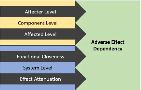
5.5 Adverse Effect Dependencies ... 42
5.5.1 Dimension of Dependencies ... 42
5.5.2 Assessing Dependencies Between Components ... 43
5.5.3 Dependency Assessment Example ... 44
5.7 Conclusion ... 49
CHAPTER 6 ARTICLE 2: INTEGRATING NEGATIVE DEPENDENCIES ASSESSMENT DURING MECHATRONICS CONCEPTUAL DESIGN USING FUZZY LOGIC AND QUANTITATIVE GRAPH THEORY ... 51
6.1 Abstract ... 51
6.2 Introduction ... 51
6.3 Research Aim and Methodology ... 54
6.4 Proposed Dependency Index ... 56
6.4.1 Randić Index ... 58
6.4.2 Normalization of the Connectivity Measure ... 59
6.4.3 Aggregation of Dependency Types ... 60
6.5 Identifying Negative Dependencies ... 61
6.5.1 Fuzzy Assessment of Dependencies Using Linguistic Variables ... 62
6.5.2 Affected Level Variation ... 64
6.5.3 Affecting Level Variation ... 66
6.5.4 Notes on the assessment of dependencies ... 67
6.6 Case Study 1: Self-Balancing Robot ... 67
6.6.1 Fuzzy Assessment of the Dependency Dimensions ... 69
6.6.2 Experimental Setup ... 72
6.6.3 Results ... 73
6.7 Case Study 2: Design of a Robotic Arm for Aerial Manipulation ... 75
6.7.1 Conceptual Design of the Manipulator ... 75
6.7.2 Dependency Assessment ... 77
6.7.3 Concept Evaluation and Selection ... 78
6.8 Conclusion ... 82
CHAPTER 7 ARTICLE 3: CONCURRENT MODELING OF POSITIVE AND NEGATIVE DEPENDENCIES USING COMPLEX NUMBERS AND ITS IMPACT ON COMPLEXITY METRICS DEVELOPMENT ... 85
7.1 Abstract ... 85
7.2 Introduction: ... 85
7.3 Research Aim, Questions and Methodology ... 88
7.4 Product-Related Dependencies: ... 89
7.5 Concurrent Modeling of Positive and Negative Dependencies ... 92
7.6 Towards the Development of New Complexity Metrics ... 96
7.6.1 Calculation of the Topological Complexity ... 96
7.6.2 Discussion on Complexity Metrics Development ... 97
7.6.3 Potential Use of Complex Dependencies: Integration Effort Analysis ... 101
7.7 Illustrative Case Study: Design Simulation of a Soft Robotic Gripper... 103
7.7.1 Case Study Background ... 104
7.7.2 Mechatronic Design of Soft Grippers: ... 104
7.7.3 Concepts Comparison ... 108
7.8 Conclusion ... 112
CHAPTER 8 ARTICLE 4: FUZZY SIMULATION BASED ROBUST DESIGN METHODOLOGY FOR MECHATRONIC SYSTEMS ... 114
8.1 Abstract ... 114
8.2 Introduction ... 114
8.3 Research Aim, Questions and Methodology ... 117
8.4 Current Robust Design Practices ... 119
8.4.2 Fuzzy Robust Design Methodologies ... 122
8.5 Fuzzy Numbers and Fuzzy Arithmetic ... 123
8.5.1 Fuzzy Numbers ... 123
8.5.2 Basic Arithmetic Operations ... 124
8.5.3 Hukuhara Difference and Division ... 125
8.6 Fuzzy Simulation Based Robust Design Methodology... 126
8.7 Case Study: Quadcopter Drone ... 129
8.7.1 Dynamics and Control ... 129
8.7.2 Fuzzy Dynamical Simulation of the Quadcopter ... 132
8.7.3 Robust Optimization and Results ... 134
8.8 Discussion ... 135
8.9 Conclusion ... 140
8.10 Appendix: Optimization Pareto Front ... 142
CHAPTER 9 HANDLING ADVERSE EFFECTS DURING THE PRELIMINARY DESIGN OF MECHATRONIC DEVICES: A FUZZY APPROACH ... 145
9.1 Introduction ... 145
9.2 Mathematical Background ... 146
9.2.1 Fuzzy Numbers ... 146
9.2.2 Fuzzy Arithmetic ... 147
9.2.3 Fuzzy Stability Analysis ... 148
9.3 Introducing Uncertainty in States ... 150
9.4 Case Study: Self-Balancing Robot ... 152
9.4.1 System Model and Control ... 152
9.4.2 Stability Analysis ... 154
CHAPTER 10 TOWARDS A FULLY INTEGRATED EARLY DESIGN METHODOLOGY
FOR THE MITIGATION OF LATE STAGE REDESIGNS ... 158
10.1 Integrated Fuzzy Robust Design Robust Control Methodology ... 158
10.1.1 Fuzzy Dynamical Simulation of Adverse Effect Induced Noise ... 159
10.1.2 Integrated Robust Design Process for Preliminary Design ... 161
10.2 Early Design Process for the Mitigation of Late Stage Redesign ... 162
CHAPTER 11 GENERAL DISCUSSION ... 165
11.1 Research Contributions ... 165
11.2 Software Implementation ... 167
11.2.1 Dependency Assessment ... 167
11.2.2 Fuzzy Simulation and System Optimization ... 167
CHAPTER 12 CONCLUSION ... 169
12.1 Summary ... 169
12.2 Future Work ... 170
BIBLIOGRAPHY ... 172
LIST OF TABLES
Table 1.1: Research Methodology Stages ... 6
Table 2.1: Handling Negative Dependencies Papers Selected Sections ... 15
Table 2.2: Fuzzy Simulation Based Robust Design Selected Sections ... 15
Table 3.1: Sample Interaction Types Adapted from [32] ... 23
Table 4.1: Mathematical and Graphical Representation of Common Fuzzy Numbers ... 26
Table 4.2: Fuzzy Linguistic Scale Examples ... 27
Table 4.3: Comparison of Simulation Time for DC Motor on Intel i7-6700K @ 4GHz ... 33
Table 5.1: 5 Level linguistic scales with TFN and TrFN values ... 40
Table 5.2: Proposed linguistic scale for describing the dimensions of a dependency ... 43
Table 5.3 : Proposed Effect Attenuation Assessment ... 44
Table 5.4: Example of Describing Components of a System ... 45
Table 5.5: List of components and their related adverse effects ... 47
Table 5.6: Functional Closeness (FC) of components ... 48
Table 6.1: Dependency Dimensions and Fuzzy Linguistic Variables Along their Graphical Representation where is the membership of the Linguistic Fuzzy Numbers ... 63
Table 6.2: Assessment of Components ... 70
Table 6.3: Closeness Assessment ... 71
Table 6.4: Effect Attenuation Assessment ... 71
Table 6.5: Fuzzy measures for Choquet integration ... 71
Table 6.6: NDI value for the runs in the design experiment ... 72
Table 6.7: Concept Evaluation with non-normalized criteria values and where criteria impact represents either a high criteria value is beneficial for the design or not ... 77
Table 6.9: Concept Evaluation with non-normalized criteria values and where criteria impact
represents either a high criteria value is beneficial for the design or not ... 80
Table 7.1: Four-Point Scale such as presented by Sharman and colleagues [111], [112] ... 91
Table 7.2: Comparison of linguistic terms using the scale from Pimmler and Eppinger [30] and the proposed complex scale ... 92
Table 7.3: Adapted Four Point Scale to Seven Point Scale ... 96
Table 7.4: Design Comparisons with Various Measures ... 110
Table 8.1: Initial Drone Nominal Parameters ... 133
Table 8.2: Comparison of Simulation Time for Quadcopter Drone in MATLAB on Intel i7-6700K @ 4GHz ... 134
Table 8.3: Lower and Upper Bounds for the Design Variables ... 135
Table 9.1: Self-Balancing Robot Parameters ... 152
Table 11.1: List of Articles ... 165
Table 11.2: Research Contributions and Related Sub-Objectives and Papers ... 166
Table 11.3: Additional Contributions ... 167
Table A.12.1:Nominal Parameter Value of the Self-Balancing Robot ... 201
Table A.12.2: Comparison of simulation time between Fuzzy method and Monte-Carlo ... 202
Table C.12.3: Mechatronic properties description ... 225
Table C.12.4: Product Capabilities for Circularity ... 229
LIST OF FIGURES
Figure 1.1: Mechatronics Domains Representation, taken from [1] ... 1
Figure 1.2: Generic Product Development Process Adapted from [5] ... 3
Figure 1.3: Research Process ... 7
Figure 1.4: Initial Reference Model for Handling Negative Dependencies ... 9
Figure 1.5: Initial Reference Model for Robust Design ... 10
Figure 1.6: Area of Relevance and Contribution Diagram ... 12
Figure 2.1: Layout of the Thesis ... 14
Figure 3.1: V-Design Process adapted from [11] ... 17
Figure 3.2 : Potential of research in conceptual design, taken from [8] ... 18
Figure 3.3: Product related dependencies as presented by [9] ... 20
Figure 3.4: Representation of positive and negative dependencies ... 21
Figure 3.5: Design Structure Matrix ... 22
Figure 3.6: DSM Built With the Method in [30]... 23
Figure 4.1: Sample Fuzzy Number ... 25
Figure 4.2: Representation of alpha-cuts ... 27
Figure 4.3: Fuzzy Linguistic Scale for (a) TFN and (b) TrFN ... 28
Figure 4.4: Principle of Fuzzy Addition ... 29
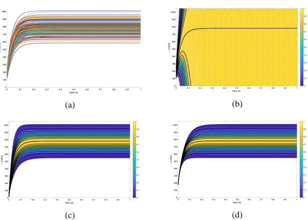
Figure 4.5: Monte-Carlo Simulation Process ... 31
Figure 4.6: Simulation Result for DC Motor for (a) Monte Carlo, (b) Standard Fuzzy interval arithmetic, (c) transformation method, and (d) Fuzzy arithmetic using Hukuhara difference and division, with the colorbar representing the membership of the response ... 33
Figure 5.1: (a) Design Structure Matrix (b) Multi-Domain Matrix ... 38
Figure 5.2: Graphical Representation of the 5 level scale for (a) TFN and (b) TrFN ... 41
Figure 5.4: Simplified model of the components of a quadcopter drone ... 47
Figure 5.5: DSM for (a) Heat, (b) Vibration, (c) EMF, (d) Combined ... 48
Figure 6.1: (a) Design Structure Matrix (b) Graph representation of the DSM ... 57
Figure 6.2: Dependency Dimensions ... 62
Figure 6.3: Set-up for assessing affecting level dimension ... 65
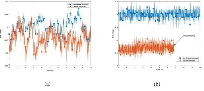
Figure 6.4: Effect of EMF on (a) MPU6050 (b) ITG3200/ADXL345 ... 66
Figure 6.5: Motor driver effect on IMU reading ... 67
Figure 6.6: Self-Balancing Robot (a) Schematic (b) Physical Implementation ... 70
Figure 6.7: (a) Unfiltered color frame of the video (b) Combined top and bottom tags filtered image, with detected position of the robot ... 73
Figure 6.8: Position of balancing robot during test for runs 1,2,3,9,10,11 ... 74
Figure 6.9: Manipulator Design Options ... 76
Figure 6.10: Robotic Manipulator Configuration for (a)-(d) concepts 1 to 4 ... 77
Figure 6.11: Closeness Assessment for (a)-(d) concepts 1 to 4 based on the manipulator layouts of Figure 6.10 ... 78
Figure 6.12: Using Negative Dependency Assessment in Simulation ... 81
Figure 6.13: Simulation Results for (a)-(d) concepts 1 to 4 ... 82
Figure 7.1: Representation of positive and negative dependencies ... 90
Figure 7.2 : Design Structure Matrix Built Using the Method in [30] ... 91
Figure 7.3 : (a) Specific Energy Dependencies (b) General Energy Dependency Representation (c) DSM of the General Dependency ... 93
Figure 7.4:(a) Multiple dependency types between two components (b) an aggregated dependency value ... 94
Figure 7.5: (a) DSM using [30], (b) DSM using Complex Notation , (c) aggregated DSM without complex number notation, (d) aggregated DSM with complex number notation ... 95
Figure 7.6: Sample Calculation of Energy and SC for DSM with (a) BUS Architecture (b) BUS Architecture with Complex Dependencies (c) Sequential Architecture (d) Sequential Architecture with Complex Dependencies (e) One module Architecture (f) One module
Architecture ... 99
Figure 7.7: (a) Positive and Negative Dependencies of Material and Energy Types (b) Aggregated Value for Dependency ... 100
Figure 7.8: Calculation of Structural Complexity Metric Elements C C on a DSM with Complex 2 3 Dependencies ... 103
Figure 7.9: Pressure Actuated Gripper with Pump (a) Functional Dependencies Schematic (b) Negative Dependencies Schematic (c) DSM (d) Aggregated DSM ... 106
Figure 7.10: Pressure Actuated Gripper Without Pump (a) Functional Dependencies Schematic (b) Negative Dependencies Schematic (c) DSM (d) Aggregated DSM ... 107
Figure 7.11: Cable Actuated Gripper (a) Functional Dependencies Schematic (b) Negative Dependencies Schematic (c) DSM (d) Aggregated DSM ... 108
Figure 8.1: Optimal vs Robust solution ... 121
Figure 8.2: Fuzzy Simulation Based Genetic Algorithm ... 127
Figure 8.3: Quadcopter dynamic model ... 130
Figure 8.4: Quadcopter control block diagram ... 132
Figure 8.5: Fuzzy step response of the initial system (a) x, (b) y, (c) z, (d) , (e) , (f) , and with the color bar representing the membership of the response ... 136
Figure 8.6: Fuzzy step response of a sample point in the pareto front (a) x, (b) y, (c) z, (d) , (e) , (f) , and with the color bar representing the membership of the response ... 137
Figure 8.7 : Evaluation procedure for the proposed approach ... 138
Figure 8.8: Comparison of Fuzzy simulation (a) and Monte Carlo Simulation (b) for non-optimized and optimized systems ... 139
Figure 8.9: Step response along for (a-b) Monte Carlo simulation of (a) initial design , (b) optimized design and (c-d) fuzzy simulation of (c) initial design, (d) optimized design .... 140
Figure 8.10: Pareto front of the design variables from the robust optimization, with the blue circle being the initial design, and the black diamond a sample point on the front. Variables 1 to 7
are and 8 to 14 their respective percent standard deviation. ... 143
Figure 8.11: Pareto front of the robust optimization objective functions, with the blue circle being the initial design, and the black diamond a sample point on the front ... 144
Figure 9.1: Visual and Mathematical Representation of a Triangular Fuzzy Number ... 147
Figure 9.2: Transferring Adverse Effect Modeling to Uncertainties in States ... 150
Figure 9.3: Self-Balancing Robot Model ... 153
Figure 9.4: Fuzzy Eigenvalues of matrix AC ... 154
Figure 9.5: Fuzzy Eigen Values of matrix A ... 155c* Figure 9.6: Fuzzy eigenvalues of A with more robust controller gains ... 156c* Figure 10.1: Fuzzy Simulation of Uncertain DC Motor ... 159
Figure 10.2: Fuzzy Simulation of PI Control for a DC Motor (a) Response (b) Controller Command ... 160
Figure 10.3: Fuzzy Simulation of PI Controlled DC Motor with Fuzzy Sensor Performance (a) Response (b) Controller Command ... 161
Figure 10.4: Proposed Robust Design Robust Control Approach ... 162
Figure 10.5: Early Design Methodology for the Mitigation of Late Stage Redesign ... 164
Figure A.1: Self-Balancing Robot Model ... 200
Figure A.2: Fuzzy Controlled State Matrix ( A−KB ) Visual Representation with ( )x being the membership of the fuzzy numbers ... 201
Figure A.3: Simulation Result of Fuzzy Method vs MCS with the color bar ( (a), (c) ) representing the possibility of the system having a certain response bound ... 202
Figure A.4: Robust Design Robust Control Optimization Using Fuzzy Simulation ... 204
Figure B.6: FeTCh Deformable Hybrid Serial-Parallel Manipulator (a) Real Implementation (b) FEM Simulation ... 208 Figure B.7: FEM of a manipulator section (a) unactuated (b) with left inflated actuator. ... 209 Figure B.8: Connection of cables for antagonistic actuation (a) for each sections (b) single cable
from base to effector ... 210 Figure B.9: (a) pressure actuator dimensions, (b) cross section of the actuator, dimensions are in
mm ... 211 Figure B.10: (a)-(c) side view of a 0Deg, 30DegOut, 20DegIn manipulator section (d)-(f) isotropic
view of 0Deg, 30DegOut, 20DegIn manipulator section ... 212 Figure B.11: Actuator positioning around the y axis ... 212 Figure B.12: Tracking of an object (sphere) for (a) cable-less section, (b) section with center cable,
(c) three cable section ... 213 Figure B.13: Simulation of the compliance measurement in SOFA ... 214 Figure B.14: (a)-(c) Compliance in displacement along x,y,z respectively. (d)-(f) Compliance in
rotation around x,y,z respectively. In (b), 10DegOut overlaps 0Deg, and 20DegIn overlaps 10DegIn ... 216 Figure B.15: (a)-(c) Compliance in displacement along x,y,z respectively. (d)-(f) Compliance in
rotation around x,y,z respectively, for 0 degree section ... 218 Figure C.16: Mechatronic V-Design Process ... 224 Figure C.17: Mapping of the Circular Design Strategies with the Product Properties ... 232 Figure C.18: Distribution of respondent based on (a) Industry sector, (b) Years of experience, (c)
Knowledge about CE (d) product’s expected lifespan in hours ... 234 Figure C.19: Reasons to design circular capabilities ... 236 Figure C.20: Reasons to design circular capabilities when companies considers eco-design/CE ... 236 Figure C.21: Most Likely Causes for Mechatronic Properties Obsolescence ... 238
LIST OF SYMBOLS AND ABBREVIATIONS
ARC Area of Relevance and ContributionCE Circular Economy
DSM Design Structure Matrix FEM Finite Element Model IRM Initial Reference Model
MCDM Multi-Criteria Decision Making MDI Mechatronic Design Indicator MDQ Mechatronic Design Quotient MIV Mechatronic Index Vector
MMP Mechatronic Multi-criteria Profile NDI Negative Dependency Index
LIST OF APPENDICES
APPENDIX A ARTICLE 5: ROBUST DESIGN SUPPORT USING FUZZY SIMULATION OF UNCERTAIN DYNAMIC SYSTEM: A SELF-BALANCING ROBOT CASE STUDY.. 195 APPENDIX B ARTICLE 6: ANALYZING DESIGN MODIFICATIONS EFFECT ON THE
COMPLIANCE OF DEFORMABLE HYBRID SERIAL-PARALLEL MANIPULATORS ... 206 APPENDIX C POTENTIAL OF CIRCULAR ECONOMY IMPLEMENTATION IN THE
CHAPTER 1
INTRODUCTION
1.1 Problem Statement
Mechatronic systems are multi-domain devices resulting from the integration of elements from mechanical, electrical, software and control engineering. They are composed of actuators, electronic systems (sensors, micro-controllers), software elements and control algorithms. These systems are present in a wide variety of products such as flight simulators or manufacturing equipment. The mechatronics domain decomposition and the various application fields are illustrated in Figure 1.1.
Figure 1.1: Mechatronics Domains Representation, taken from [1]
Although mechatronic devices are highly versatile, their multi-domain nature results in multiple complex relationships being present between the involved engineering domains [2], [3]. These relationships need to be addressed as early as possible in the design process to ensure near optimal designs and design activities. Hence, the design of mechatronic devices is highly challenging, and the design research community intensively works towards developing and improving multi-domain design methodologies.
One issue that needs to be addressed during the design process, arising from these complex relationships, is the costly late stages redesigns. Late stages redesigns could occur in mechatronics due to unpredicted integration issues, for instance where elements of the systems negatively interact with one another, resulting in a loss of performance or inability to achieve the desired requirements.
One of the causes of the late stages redesigns are adverse effect dependencies, which occur when normally operating components/subsystems induce noise that will deteriorate the performance of other components/subsystems [3], [4]. These dependencies are difficult to predict since they can be resulting from a range of factors, and might be unnoticeable if the components/subsystems are designed by different teams of engineers. Hence, there is a crucial need to develop multi-domain methodologies to identify as early as possible these adverse effects and thus mitigate their effect during integration.
Moreover, another challenge associated with mechatronic devices, and which can result in costly redesigns, is their decreased performance under uncertainties. Uncertainties in the design may arise from the fabrication process, deterioration of the components, or from the unpredictable operating environment. Consequently, on top of dealing with customer specifications and requirements, a mechatronic system needs to be performing in a robust manner. Ensuring that a mechatronic device is robust is challenging since the performance will be directly linked to the robustness of the structure (mechanical), robustness in the sensor performance (electronics), robustness in the controller (control), and robustness in the decision algorithm (software). Robustly designing mechatronic devices thus requires well-adapted methods to ensure an efficient and effective design process.
Many challenges thus need to be addressed during the design of mechatronic systems to avoid costly redesigns. Consequently, there is a need to create methods, tools, and knowledge that will support the mechatronic engineers during the design process. Moreover, these methods and tools need to be used as early as possible in the design process to avoid time consuming redesigns when reaching the later stages. This PhD thesis subscribes into the above-mentioned lines of research work in terms of:
1. Adverse effects consideration and modeling, 2. Robust design.
1.2 Research Basis
1.2.1 Research Identification
The aim of this research is to support mechatronic engineers achieve a more time and cost efficient mechatronic design process while allowing to obtain optimal systems. This work thus researches on the phenomena of late stage redesign loops during mechatronics development. A late stage redesign is referred to as the need to modify the design during system integration, either during prototyping or manufacturing, due to inadequate performances. The generic product development process with the late stages redesigns is shown in Figure 1.2.
Figure 1.2: Generic Product Development Process Adapted from [5]
The inadequate performance can be a direct, or indirect, result of negative dependencies or unaccounted uncertainties. Therefore, this research is based on the assumptions that:
• Identifying negative dependencies, and more precisely adverse effect dependencies, in early design stages should help mechatronic engineers to mitigate them early on and reduce redesign
• Enabling more time-efficient robust design methodology should help in allowing a larger design space to be explored, and thus mitigate the effect of uncertainties on the performance. This should then avoid redesigns due to unaccounted factors.
Consequently, the goal is to develop methods and tools that would help in better handling negative dependencies and carry out more efficient robust design methodology during the early design stages. This PhD thesis will thus try to answer the following research questions.
➢ RQ1: How can negative dependencies be identified early during the design process? • What are negative dependencies in mechatronic systems?
• How can negative dependencies be modeled early during the design process? ➢ RQ2:How can negative dependencies be used in early design stages?
• How can negative dependencies modeling be integrated to the decision-making process?
• What decision-making tool would allow effective use of negative dependencies? ➢ RQ3: How can mechatronic systems be robustly designed in an efficient and effective
integrated manner?
• What computationally efficient method can be used to compute uncertain response properties?
• Which optimization process can be used for an effective robust design methodology in mechatronics, and which will allow to consider the multi-domain objectives? ➢ RQ4: How can the effect of negative dependencies be integrated while carrying out a robust
design methodology on mechatronic devices?
1.2.2 Research Hypothesis
This research uses one main research hypothesis:
Fuzzy numbers can be used to capture uncertainties related to the identification of negative dependencies early during the design process while also enabling to develop
computationally efficient robust design methodologies.
It is therefore hypothesized that by using fuzzy numbers, it will be possible to support mechatronic engineers in the early design stages.
1.2.3 Research Objectives
Based on the previously enumerated research questions and hypotheses, the main research objective of this thesis is stated as follows.
Developing design support tools that use fuzzy numbers and which would allow to mitigate late stages redesigns
➢ SO1: Develop a methodology to assess and model negative dependencies during the conceptual design phase using fuzzy numbers.
➢ SO2: Develop a method to integrate negative dependency modeling of SO1 in the decision-making process during the conceptual design phase.
➢ SO3: Develop a robust optimization process that would:
• Use fuzzy numbers to obtain uncertain performance properties of mechatronic devices
• Integrate the dependency modeling of SO1
1.2.4 Research Methodology and Research Process
In order to achieve the above-mentioned objectives and sub-objectives this project follows the three steps methodology.
• Dependency Assessment: This will be handled by the development of a multi-dimensional dependency that will enable the appropriate assessment of the various dependencies existing between the subsystems. Based on the classification of product related dependencies presented in [3], it is possible to use these categories as reported in [6] such as adverse effect.
The defined categories will allow to determine a level of dependency between the subsystems based on the number of product related dependencies. In order to account for the design-related uncertainties, fuzzy numbers will be assigned to the various dependency dimensions. Finally, the modeling and assessment of the dependency will be done in a design structure matrix.
• Decision Making During Conceptual Design: The modeling of the dependency using the design structure matrix needs to be used during decision making. To do so, elements from graph theory will be used to consolidate the various dependencies into an index usable during decision making. This index will then be tested with various case studies to ensure that it properly represents the reality of the design.
• Robust Optimization: The need for an efficient and effective robust design methodology will be handled using fuzzy simulation. The fuzzy simulation will use principles of fuzzy arithmetic to calculate the uncertain response. This should allow to save computational time. Then, the uncertain dynamic response will be used in an optimization loop, where the aim will be to reduce the fuzzy uncertainty.
Moreover, this research has been accomplished following the Design Research Methodology as suggested in [7]. In the subsequent sections, elements from the methodology such as the Initial Reference Model (IRM) and the Area of Relevance and Contribution (ARC) diagram will be presented. Moreover, following the design research methodology of [7], the research stages are : Research Clarification, Descriptive Study 1, Prescriptive Study, Descriptive Study 2. These stages are clarified in Table 1.1.
Table 1.1: Research Methodology Stages
Stage Description
Research Clarification (RC) To clarify current understanding of the existing situation while identifying research goals, research questions, and research hypotheses
Descriptive Study 1 (DS1) To obtain a detailed understanding of existing situation while suggesting factors to address during the PS stage.
Prescriptive Study (PS) To develop a design support and its evaluation plan
Descriptive Study (DS2) To evaluate the usability and usefulness of the design support
For each of the research questions presented in the previous section, the aforementioned stages will be carried out following the process in Figure 1.3. It can thus be seen that the various methods developed will be tested and improved based on the tests’ evaluation. Moreover, insight and
knowledge acquired from previously developed methods will be used in the development of the other subsequent methods.
Figure 1.3: Research Process
1.2.5 Line of Argumentation
Throughout this work, two main lines of argumentation will be used to demonstrate the need to mitigate late stage redesigns. To express this, an initial reference model (IRM) will be used [7]. An IRM expresses the relationship between various factor of influence. It is possible to describe in a
visual manner what is the effect of the increase (+) or decrease (-) of one of the factors on a subsequent factor while enabling to state whether it is based on assumptions, literature or experience.
First, the late stage redesigns may be linked to the improper integration of the various subsystems. Indeed, it is often challenging to deal with complex systems as their structure will be divided into smaller modules, which will be developed by different teams. However, optimizing individual modules, or subsystems, may not necessarily result in an optimal system due to negative interactions. These negative interactions may thus lead to late stages redesigns, where integration is done, and would result in costlier development process. The IRM for this issue is displayed in Figure 1.4.
Furthermore, another factor that would affect the redesign is improper system performance due to unaccounted uncertainties. Indeed, no process being perfect, there will always be tolerances that will need to be specified for the mechanical or electrical components. Moreover, varying operating conditions (dust, humidity, wind, temperature) could lead to a perturbation in the performance of the system. If the uncertainties are not included from the beginning in the design process, this may lead to costly redesigns when prototypes or manufactured devices are tested/used and they don’t meet initial requirements. The IRM for this second issue is shown in Figure 1.5.
Figure 1.4: Initial Reference Model for Handling Negative Dependencies Nu m b e r Ne ga ti ve D e p e n d e n ci e s In te gr at ed D e si gn Pro ce ss Co mp le xi ty Le ve l o f Sy st e m Pe rf o rma n ce Le n gt h o f D e si gn Pr o ce ss Nu m b e r o f la te s ta ge re d e si gn St re n gt h N eg at iv e D e p e n d e n ci e s Co st o f D e si gn Pr o ce ss [L, A ] Us e o f In te gr at e d D e si gn Pr o ce ss Nu m b e r o f in -d e si gn it te ra ti o n s -+ + + -+ -+ + + + + + + + + -[A] [L, A] [A] [L] [L, E] [E ] [L, E] [E ] [L, E, A ] [E ] + -Le ve l o f Cr o ss -D o ma in al it y Nu m b e r o f In te ra ct io n s/ D e p e n d e n ci e s In h er en t Sy st e m Co mp le xi ty + + + + + + + + [L, E, A] [L, E, A ] [L, A ] [E] + + Si ze o f la te sta ge re d e si gn + + + [L] = Litt e ra tu re [E]= Ex p er ie n ce [A ]= A ss u mp ti o n Ro o t o f Pr o b le m Id e al O u tc o me Re se ar ch Fo cu s Me as u ra b le O u tc o me + + +
Figure 1.5: Initial Reference Model for Robust Design D yn ami c O p er at in g En vi ro n men t + + + [L, E, A] [L, A ] [L, A] + [L] = Litt e ra tu re [E]= Ex p er ie n ce [A ]= A ss u mp ti o n Ro o t o f Pro b le m Id e al O u tc o me Re se ar ch Fo cu s Mea su ra b le O u tc o me Lev el o f Sy st e m Pe rf o rma n ce Ma n u fa ct u ri n g To le ra n ce s Co mp o n e n t D e to ri o ra ti o n U n ac co u n te d D yn ami c Beh av io r D e cr e as e o f Co mp o n e n t Co st + + + Le n gth o f D e si gn Pro ce ss N u m b er o f la te s ta ge re d e si gn Co st o f D e si gn Pro ce ss N u m b er o f in -d e si gn it te ra ti o n s Si ze o f la te st ag e re d e si gn + U n certa in Re sp o n se Pro p er ti e s Co st o f th e D e si gn -+ + + + -+ + + + + + + + + [L, A ] [L, A ] [E ,A ] [E, A] [E ,A ] [A ] [A] [A] [A ] [E, A] [A] [A]
1.2.6 Research Contribution and Deliverables
This thesis contributes to the existing knowledge in various ways. To illustrate the contribution, an area of relevance and contribution (ARC) diagram [7] is shown in Figure 1.6. ARC diagrams allow to represent through a model, similar to a mind map, which knowledge bases are necessary for the current work and to which knowledge bases the work contributes. The contribution of this Ph. D. work is summarized as:
1. A method that allows to identify adverse effects early during the design process
2. A complexity metric that represent the level of negative dependencies present in a system, and which can be used as a criterion for concept evaluation
3. A design methodology that uses fuzzy simulation to robustly optimize mechatronic devices
Finally, the deliverable of this PhD work is in two parts:
1. A series of 6 research articles relating the scientific development and contributions accomplished during the span of the PhD studies
2. A set of freely available numerical tools1, and their respective documentation, that would allow:
a. the identification of negative dependencies early during the design process,
b. the integration of negative dependency modeling during early design decision-making,
c. to carry out efficient and effective robust design methodology with the information available during early design stages
CHAPTER 2
HOW TO READ THIS THESIS
The work in this thesis is reported in a paper-based format. Figure 2.1 displays the layout of this work, along the various papers that were written. Being highly linked together, the introduction and literature review sections of the various papers may seem redundant if read for each article. Hence, a collection of the papers’ introduction has been integrated into a single section for this thesis, in the literature review. Therefore, the reader will instead be directed towards the core parts of the research articles. Provided that the background information section has been previously read, doing so should ensure a more streamlined and more pleasing reading. The reader is obviously more than welcome to go through every research article as a whole. The two streams part of the core of the thesis (Paper 1-5) are further detailed in the following sub-sections. Finally, the other paper that is not in the thesis’ core (Paper 6) can be read entirely as it does not have similar background. Paper 5 is provided in Appendix B. Finally, Appendix C provides an unpublished/non-submitted paper (at the time of writing) that investigates the subject of circular economy in mechatronics.
Figure 2.1: Layout of the Thesis
2.1 Handling Negative Dependencies
At first, Article 1 suggests a new method for identifying adverse effect dependencies using knowledge available during the conceptual stage. The developed method uses fuzzy linguistic variable, such as presented in Section 4.2, to describe 4 dimensions defining an adverse effect. This dependency identification method allows to obtain a DSM of the system. Then, Article 2 suggests a graph theoretic approach to condense the information of the DSM, obtained from the method in Paper 1, into an index that can be used in decision-making. Article 1 and Article 2 only considers negative effects. To cope with this, Article 3 suggest a method for better concurrently handling positive and negative dependencies at both the system modeling level, and system analysis level. The sections for a streamlined reading, continuing from Chapter 3 and Chapter 4, are listed in Table 2.1.
Table 2.1: Handling Negative Dependencies Papers Selected Sections
Article Sections
1: Assessment of Dependencies in Mechatronics Conceptual Design
of a Quadcopter Drone Using Linguistic Fuzzy Variables
5.5, 5.6, 5.7
2: Integrating Negative Dependencies Assessment During
Mechatronics Conceptual Design using Fuzzy Logic and Quantitative Graph Theory
6.3, 6.4
6.5 except 6.5.1 6.6, 6.7
3: Concurrent modeling of positive and negative dependencies
using complex numbers and its impact on complexity metrics development
7.2, 7.5-7.8
2.2 Fuzzy Simulation Based Robust Design
Two papers were written based on the fuzzy simulation of mechatronic systems, Paper 4 and Paper 5. Paper 4 is the first try at using fuzzy simulation to carry out robust design methodology. Paper 5 is more an exploratory work: it uses a slightly different arithmetic than in Paper 4 with another case study, which was intended to confirm the suitability of fuzzy simulation. Furthermore, a third paper has been written based on the analysis of mechatronic systems using fuzzy number. Paper 6 suggests a method that can be used to include the modeling of the adverse effects in the dynamic model of the system and analyze its stability. Table 2.2 shows which sections are relevant for the reader to go through.
Table 2.2: Fuzzy Simulation Based Robust Design Selected Sections
Article Sections
4: Fuzzy Simulation Based Robust Design Methodology for
Mechatronic Systems
Full Paper Except Section 8.2.5
5: Robust Design Support using Fuzzy Simulation of Uncertain
Dynamic System: A Self-Balancing Robot Case Study
In appendix A: A.4, A.5, A.6
Handling Adverse Effects During the Preliminary Design of Mechatronic Devices: A Fuzzy Approach
CHAPTER 3
LITTERATURE REVIEW
3.1 Mechatronic Design Process
As any other products, mechatronic devices have to go through various design stages. These stages are defined as Conceptual Design, Detailed Design and Design Production [8]. The conceptual design of a product consists of generating various potential solutions and then choosing the most suitable one based upon evaluation of the design criteria. The detailed design takes the winning concept and analyzes the various components in order to determine the required properties so that the desired design characteristics are met. Finally, the design production is the stage where decisions are made as to which processes will be employed in order to manufacture the product. Moreover, there is often a fourth stage that is considered in mechatronic design: the preliminary phase. Preliminary design is usually carried out between the conceptual phase and the detailed design as a means of obtaining initial dimensions and control parameters.
The traditional process is to design mechatronics in a sequential manner, where first the elements from the mechanical domain are designed, then electronics, and finally the control method and algorithms are developed. However, mechatronic systems, and their subsystems, are subjected to complex dependencies. These dependencies can negatively affect the performances of the overall system by making product integration activities more complex. These dependencies may result in costly and time consuming redesign if they are detected late during the design process[9]. Hence, it is of the utmost importance to design the mechatronic systems concurrently in order to achieve a near optimal device [10]. The concurrent design allows design engineers to avoid the trap of spending too many resources achieving optimal subsystems in a specific domain while taking the risk of not forming an optimal integrated device [3]. This concurrent process is often referred to as integrated design.
The usual method to carry out an integrated design methodology is by following the V-Design approach, where first a system level design is carried out, then a concurrent domain specific one, and finally system integration is achieved, and this for each of the design stages. The V-Design process for mechatronic development is shown in Figure 3.1.
Figure 3.1: V-Design Process adapted from [11]
However, there exists many identified challenges related to the design of mechatronic systems [2], with the most notable and important being product related. Product related challenges can be associated with the difficulty in assessing the consequences of choosing between design alternatives, lack of common design language and to the difficulty of transferring information between the different engineering disciplines within product design process [2]. For assessing the consequences of selecting an alternative between two product concepts, the authors in [2] identifies four solutions: Relationship management (Design Structure Matrices, Domain Mapping Matrices), Informal descriptions (A3 overviews [12]), Formal language description (SysML [13]) and Mechatronic concept description, and finally simulation of phenomena (modelica, bond graph [14], [15]).
Furthermore, the lack of common design language, unifying the design activities in the different engineering domains, can be addressed by controlling design activities through requirements management (systems engineering), and again by informal description and modeling language. Finally, the challenge of transferring information can be dealt with by using systems engineering and design model transformation [16].
To better deal with the aforementioned challenges, each of the design stages in the V-design process requires well-adapted methods. Nevertheless, it is stated in [8] that although the conceptual design stage is the one having the highest impact on the final product, it is also the one having the least amount of available tools. It thus provides the highest opportunity for research as shown in Figure 3.2. Hence, there is a need to improve conceptual (and preliminary) design tools to facilitate the design process. The currently existing methods for the early mechatronic design stages (conceptual, preliminary), and their common drawbacks, are described in the following section.
Figure 3.2 : Potential of research in conceptual design, taken from [8]
3.2 Integrated Conceptual Design of Mechatronic Systems
Multiple research works have been carried out in order to develop integrated conceptual design methodologies to facilitate decision-making. One of such is the Mechatronic design quotient (MDQ) [17], which consists of assessing the degree to which a subsystem, such as a motor, satisfies the design requirements (speed, weight, cost) using a percentage based level of satisfaction towards the desired properties. The MDQ has further been used to evaluate elite concepts of mechatronic systems where, in this case, the system was seen as a whole and therefore the design criteria were assessed for the entire system [18]. The Mechatronic Index Vector (MIV) as proposed by [19], [20] considers three elements important to mechatronic systems (complexity, intelligence, flexibility) and uses a fuzzy linguistic scale to measure performance of the elements [19]. Another solution developed for integrated design in a preliminary stage , which as stated previously bridges between
conceptual and detailed design, is the Mechatronic Design Indicator (MDI) [21] that consists of assessing the overall design performance of the system through a weighted aggregation of performance metrics (ex: speed of response, accuracy, stability). This assessment is carried out in [21] through the training of a neural network which is used in order to aggregate the various metrics.
An approach combining the MDQ and MIV is developed in [22]–[24]. The authors introduce the multi-criteria mechatronic profile (MMP), which consists of a vector comprising the most important criteria for mechatronic design: namely the machine intelligence quotient, reliability score, complexity, flexibility, and cost. MMP aggregates the criteria in order to obtain a global design score that can be used by the design engineer for decision support.
Finally, the authors in [25] suggest to use the abilities of the mechatronic system to evaluate a concept’s preformance. These abilities are described as the adaptability, configurability, dependability, etc. The authors use a scale to describe and evaluate the capacity of the system towards the abilities, and then aggregate the evaluation using the Choquet integral to form a global concept score.
Although the MDQ, MDI, MIV, and MMP are integrated conceptual design methods, they only consider the whole system during the evaluation of the various criteria and not how each component/sub-system contributes to the performance required by the design criteria. Furthermore, both the MDQ and MMP evaluate “elite” concepts that are selected by the designer which might omit the actual optimal solution. Finally, none of them entirely consider the complex relations/dependencies between the various subsystems involved in the design process even though it is one of the major issues to deal with during the design process.
3.3 Dependencies in Mechatronics
A dependency is defined as being the relationship that exists between two elements (components, subsystems, systems) whenever one of them (the dependent) is affected by the other (the antecedent). However, a dependency is not limited to components/systems. Indeed, a dependency can be defined between functions (provide power), means (battery), and properties (power capacity). The research work presented in [3] proposes a classification scheme for product related dependencies that can be utilized when modeling a mechatronic system as shown in Figure 3.3.
Furthermore, these dependencies can also be classified as being intra-package, intra-system, inter-system, intra-domain and inter-domain [26]. They shall be defined, lacking formal definition specific to mechatronics, as such:
• Intra-Package: A dependency that exists within a component such as the type of battery (mean) and the durability (property)
• Intra-System: A dependency that exists within a system such as the one existing between a motor’s function to create motion and a battery’s function to provide power.
• Inter-System: A dependency that exists between two systems such as drive-by-wire steering device command system and wheel actuation system.
• Intra-Domain: A dependency that exists within a domain of engineering such as two functions related to an engine piston motion: linear-to-rotational motion transformation and induce vibration.
• Inter-Domain: A dependency that will exist between two domains such as the adverse effect of a motor vibration (mechanical/electrical) on an accelerometer (electronics)
Finally, a dependency can be said to be either positive or negative. A positive dependency is one that helps fulfill the functional requirements of the system. For instance, the dependency between the battery (a means) and a motor (another means) is said to be positive as it works towards meeting the functional requirement of the system.
Negative dependencies can occur in various forms where one of the common type would be the noise (heat,vibration, electro-magnetic field) induced by functioning components. Other negative dependencies are for instance the premature oxidation of components within a product due to interacting materials. Regardless the form of the negative dependency, they will often result in the deterioration of product performance and integrity.
An example of a negative dependency is the one that could exist between a battery and a sensor, when the heat generated by the battery affects the measurement of the sensor. We illustrate the examples of positive and negative dependencies in Figure 3.4.
Figure 3.4: Representation of positive and negative dependencies
3.4 Dependency Modelling Using the Design Structure Matrix
Even though the classification of dependencies can ease their identification, dealing with them still remains a complex task and thus multiple researchers work toward improving methodologies to do so. The research reported in [27] presents how SysML can be used to represent semantic relationships. Other tools such as the Design Structure Matrix (DSM) can be applied to model system architecture, organization structures, processes and low-level relationships [28].
A DSM is in fact the adjacency matrix of a graph. It thus represents the dependencies that would exist between the components of a system using a square matrix of dimension n ; n being the number of components in the system. The components of the systems would then be the nodes of the graph, while the dependencies the edges. Using the DSM would then require to insert a marker in the matrix at row = i , column = j to the express the relationship that exists between the antecedent i and the dependent j . An example of a DSM is shown in Figure 3.5. Moreover, Domain Mapping Matrices [29] can be used to map the relations and dependencies between domains in a system and thus can extend the DSM to be used in complex product development. Finally, by using DSMs and DMMs together it is possible to form a Multi-Domain Matrix (MDM) which would then allow to represent all the component/domain interactions of the system.
Figure 3.5: Design Structure Matrix
The DSM is only a means of representing the relationship between any pair of elements, as compared to SysML which is a modeling language having its own syntax and ontology. Regardless, there still exist modeling methods such as proposed by [30] that helps identifying the dependencies (spatial, energy, material, information) to be entered in the DSM using a linguistic scale describing whether the dependency is detrimental, undesired, indifferent, desired, or required. A synthetic DSM using this method is shown in Figure 3.6.
Figure 3.6: DSM Built With the Method in [30]
Alternatively, the authors in [31], [32] suggest the use of a high definition design structure matrix (HDDSM). The HDDSM uses the generic types of interactions in [30] and add a lower abstraction level in their description. This allows to describe the interactions in a more specific manner. A sample of the specific types is displayed in Table 3.1. Consequently, it should be possible to define the interaction as being “Control Information” instead of only “Information”. This modeling method should thus allow to have a more detailed view of the system that is being developed, and potentially result in better analysis and module creation.
Table 3.1: Sample Interaction Types Adapted from [32]
General Type Information Material Energy Spatial Movement
Specific Types Status Control Gas Liquid Solid Chemical Electrical Hydraulic Magnetic Proximity Alignment Translational Rotational
Furthermore, the work in [33] suggests to model functional dependencies of mechatronic systems based on three dependency types: Material, Energy and Information. They also extend the functional dependency to a secondary type, such as done in [32], to better represent the information. However, instead of using a DSM, the authors in [33] suggest the modeling of dependencies using subsystems/components networks, which is done along the capture of the dependencies’ strength. A lot of research is done around the DSMs as they are widely employed due to their ease of use. Indeed, the DSM ca be used to easily model a system by using a simple spreadsheet, while still remaining a compact representation of information. Although DSM are easy to use, they are still
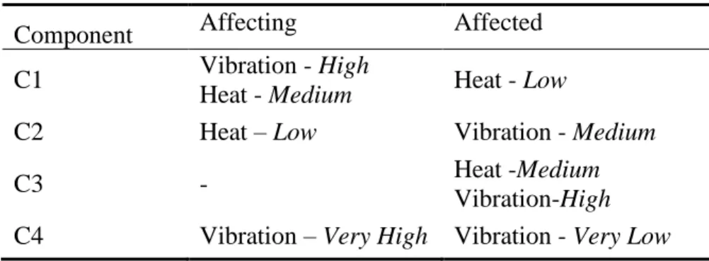
time consuming for the design team. Indeed, it would be required to go over all potential interactions in order to properly model the system. Consequently, recent work has been performed to use some of the product related dependencies in order to develop a scheme to detect them at an early design stage by using an affecter and affected duality [20]. The former consists of determining which components affect other components by considering adverse effects (such as heat release and vibrations).
Many of the presented techniques are used to model dependencies but do not enable to formally quantify the level of dependency that exists within a system. Even though some quantifications are used in DSM, it is mainly a designer-based measure and thus the measure might not be transferable to other systems, while being prone to uncertainty. Therefore, to deal with the imprecision this thesis will propose, in the subsequent chapters, to exploit fuzzy-logic based fuzzy numbers. Fuzzy numbers will not only allow the possibility to capture the uncertainty in the assessments of the designers, but also enable fast computing of uncertain system response resulting from the negative dependencies.
CHAPTER 4
MATHEMATICAL BACKGROUND ON FUZZY
NUMBERS
4.1 Fuzzy Numbers
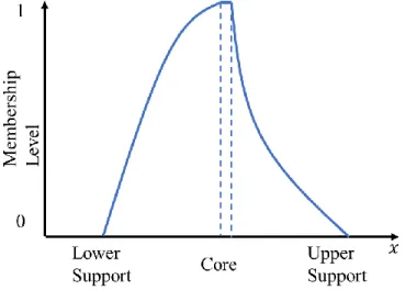
Fuzzy numbers are bounded fuzzy sets which also have the properties of being normal, convex, and upper semicontinous [34], [35]. They represent imprecise information (uncertainty), as compared to the classical real numbers (often referred to as “crisp” numbers) which represent precise or exact information. Fuzzy numbers have a membership level
( )x , specified between [0,1], and which represents the possibility of a value being a member of the number. Consequently, the membership at the center of the number, referred to as the core of the fuzzy number, is 1 and outside the supports, which bound the number, is 0, such as shown in Figure 4.1. Some of the widely used fuzzy numbers are for instance triangular or trapezoidal in shape.Figure 4.1: Sample Fuzzy Number
One way to represent fuzzy numbers is through a membership function, which expresses how the membership level varies. In this thesis, the LR representation of a fuzzy number [35] will be used, where it is possible to describe the membership of the fuzzy number by its left and right curves. A trapezoidal (TrFN) fuzzy number can thus be given by u=TrFN a b c d( , , , )L R, , where a d, are
fuzzy number would have the same membership function as the trapezoidal one, but with b=c . Table 4.1 displays two common fuzzy numbers that will be used throughout this work: Trapezoidal (triangular), and Gaussian.
Table 4.1: Mathematical and Graphical Representation of Common Fuzzy Numbers
Type Membership Function Graphical Representation
Tr iangula r/ Tr ape zoid al 0 if if ( ) 1 if if 0 if x a x a L a x b b a x b x c d x R c x d d c d x − − = − − Ga ussi an 2 2 2 2 0 if ( ) exp if 2 ( ) ( ) exp if 2 0 if l l l r r r x x c x x L x c x x x x x R x x x c x c x − − − − = − − + +
Furthermore, when working with fuzzy numbers, it is customary to discretize them along their membership level. This discretization is referred to as the
−
cuts
, and represents an interval at a certain membership level. The discretization is thus be given by 0=0 1 ... N = and the 1 resulting fuzzy number mathematical representation by [ ]x a =[ ,x x− +] with x x−, + being the lower and upper bound of the interval at a given
−
cut
. This is further illustrated in Figure 4.2.Figure 4.2: Representation of alpha-cuts
4.2 Fuzzy Linguistic Variables
This special type of fuzzy numbers, originally proposed by [36] allows to describe an event or statement using words. Then, by considering standard triangular/trapezoidal fuzzy membership functions, each component of the linguistic scale is associated to a triangular fuzzy number (TFN) or a trapezoidal fuzzy number (TrFN), which then allows to capture the uncertainty associated with the linguistic statement. The uncertainty is thus captured by the support around the core of the fuzzy numbers. These special fuzzy numbers have been employed in Kansei engineering [37], [38] or to evaluate the appropriateness of alternatives [39]. A more extensive list of fuzzy linguistic scales and their use is provided by [40]. Using words to describe a phenomenon is usually more intuitive than using only a number. Hence, their use in engineering conceptual design is convenient. An example of a linguistic scale is presented in Table 4.2 with their respective graphical representation in Figure 4.3.
Table 4.2: Fuzzy Linguistic Scale Examples
Very low Low Medium High Very high
TFN (0,0,0.2) (0.05,0.25,0.45) (0.3,0.5,0.7) (0.55,0.75,0.95) (0.8,1,1)
![Figure 1.5: Initial Reference Model for Robust Design Dynamic Operating Environment+++[L,E,A][L,A][L,A]+[L] = Litterature[E]= Experience[A]= AssumptionRoot of ProblemIdealOutcomeResearchFocusMeasurableOutcomeLevel of SystemPerformanceManufacturing TolerancesComponentDetoriorationUnaccountedDynamic BehaviorDecrease of Component Cost+++Length of DesignProcessNumber of late stageredesignCost of DesignProcessNumber of in-designitterationsSize of latestage redesign+UncertainResponsePropertiesCost of theDesign-++++-+++++++++[L,A][L,A][E,A][E,A][E,A][A][A][A][A][E,A][A][A]](https://thumb-eu.123doks.com/thumbv2/123doknet/2327327.30764/31.918.249.648.120.1032/problemidealoutcomeresearchfocusmeasurableoutcomelevel-systemperformancemanufacturing-tolerancescomponentdetoriorationunaccounteddynamic-behaviordecrease-designprocessnumber-designprocessnumber-designitterationssize-uncertainresponsepropertiescost.webp)
![Figure 3.2 : Potential of research in conceptual design, taken from [8] 3.2 Integrated Conceptual Design of Mechatronic Systems](https://thumb-eu.123doks.com/thumbv2/123doknet/2327327.30764/39.918.243.672.372.624/figure-potential-research-conceptual-integrated-conceptual-mechatronic-systems.webp)
![Figure 3.3: Product related dependencies as presented by [9]](https://thumb-eu.123doks.com/thumbv2/123doknet/2327327.30764/41.918.120.804.574.1035/figure-product-related-dependencies-presented.webp)
![Table 3.1: Sample Interaction Types Adapted from [32]](https://thumb-eu.123doks.com/thumbv2/123doknet/2327327.30764/44.918.116.813.658.784/table-sample-interaction-types-adapted.webp)