HAL Id: tel-01382324
https://hal-lirmm.ccsd.cnrs.fr/tel-01382324v2
Submitted on 18 Jan 2019
HAL is a multi-disciplinary open access archive for the deposit and dissemination of sci-entific research documents, whether they are pub-lished or not. The documents may come from teaching and research institutions in France or abroad, or from public or private research centers.
L’archive ouverte pluridisciplinaire HAL, est destinée au dépôt et à la diffusion de documents scientifiques de niveau recherche, publiés ou non, émanant des établissements d’enseignement et de recherche français ou étrangers, des laboratoires publics ou privés.
management in component-based software development
processes
Abderrahman Mokni
To cite this version:
Abderrahman Mokni. A formal approach to automate the evolution management in component-based software development processes. Other [cs.OH]. Université Montpellier, 2015. English. �NNT : 2015MONTS131�. �tel-01382324v2�
systems are subject to changes to extend their functionalities, correct bugs, improve performance and quality, or adapt to their environment. If not evolved, software systems degrade, become obsolete or inadequate and be replaced. While unavoidable, software changes may engender several inconsistencies and system dysfunction if not analyzed and handled carefully hence leading to software degradation and phase-out.
This thesis proposes an approach to improve the evolution management activity in component-based software development processes. The solution adopts a Model-Driven Engineering (Mde) approach. It is based on Dedal, an Architecture Description Language (Adl) that explicitly separates software architecture descriptions into three abstraction levels: specification, configuration and assembly. These abstraction levels respectively correspond to the three major steps of component-based development (de-sign, implementation and deployment) and trace architectural decisions all along development. Dedal hence efficiently supports evolution management: It enables to determine the level of change, analyze its impact and plan its execution in order to prevent architecture inconsistencies (erosion, drift, etc.). Rigorous evolution management requires the formalization, on the one hand, of intra-level relations linking components within models corresponding to different architecture abstraction levels and on the other hand, of the formalization of inter-level relations linking models describing the same architecture at different abstraction levels. These relations enable the definition of the consistency and coherence properties that prove necessary for architecture correctness analysis. The evolution process therefore consists of three steps: First, change is initiated on an architecture description at a given abstraction level; then, the consistency of the impacted description is checked out and restored by triggering additional changes; finally, the global coherence of the architecture definitions is verified and restored by propagating changes to other abstraction levels.
Relations and properties are expressed in B, a set-theoretic and first-order logic language. They are applied on B formal Adl the meta-model of which is mapped to Dedal’s and helps automatic model transformations. This integration enables to implement a development environment that combines the benefits of both Mde and formal approaches: Software architecture design using Dedal tools (graphical modeler) and architecture analysis and evolution management using B tools (animator, model-checker, solver).
In particular, we propose to use a B solver to automatically calculate evolution plans according to our approach. The solver explores a set of defined evolution rules that describe the change operations that can apply on architecture definitions. It automatically searches for a sequence of operations that both changes the architecture as requested and preserves architecture consistency and coherence properties. The feasibility of the evolution management approach is demonstrated through the experimentation of three evolution scenarios, each addressing a change at different abstraction level. The experimentation relies on an implementation of a search-based software engineering approach mixing software engineer-ing and optimization and integrates our own solver with specific heuristics that significantly improve calculation time.
Tout d’abord, je remercie Monsieur Yannick Vimont, directeur du Laboratoire de G´enie In-formatique et d’Ing´enierie de Production (LGI2P) de l’ ´Ecole des Mines d’Al`es pour m’avoir accueilli et permis de r´ealiser cette th`ese dans les bonnes conditions.
Je voudrais par ailleurs remercier l’ensemble des membres du jury. Je remercie particuli`erement Messieurs Yves Ledru et Salah Sadou pour avoir accept´e de rapporter ma th`ese. Je remer-cie ´egalement Messieurs Antoine Beugnard, David Delahaye et Philippe Collet d’avoir accept´e d’examiner mon travail.
Je tiens `a remercier tout particuli`erement et `a t´emoigner ma reconnaissance envers mon ´equipe encadrante pour leurs grandes qualit´es professionnelles et humaines : Madame Marianne Huchard pour avoir dirig´e ce travail de th`ese, Madame Christelle Urtado pour ses conseils judicieux et sa p´edagogie. Elle a su toujours me motiver et me remonter le moral pendant les p´eriodes difficiles de la th`ese. Sylvain Vauttier avec qui j’ai eu beaucoup de plaisir `a travailler ; ses ´echanges, ses discussions et ses conseils ´etaient tr`es enrichissants.
Je remercie l’ensemble du personnel technique et administratif du LGI2P. Toujours disponibles et aimables. Merci aux enseignants-chercheurs, doctorants, post-doctorants et ing´enieurs qui m’ont toujours bien accueilli et furent souvent d’une aide pr´ecieuse. Je tiens particuli`erement `
a remercier mes coll`egues et amis : St´ephane Billaud, Sami Dalhoumi, Balzo Nastov, Pierre-Antoine Jean, S´ebastien Harispe et Abdelhak Immousaten avec qui j’ai partag´e beaucoup de beaux moments pendant les trois ann´ees de th`ese.
Pour finir, je remercie ma famille qui m’a toujours accompagn´e et encourag´e (malgr´e la dis-tance), mes parents, pour leur ´education et leur amour, `a jamais dans mon cœur.
1 Introduction 1
1.1 Context of Component-Based Software Engineering . . . 1
1.2 Problematic of architecture evolution in CBSD processes . . . 2
1.3 Thesis proposal and contributions. . . 3
1.4 Dissertation outline. . . 4
2 Context of component-based software engineering and software architec-tures 7 2.1 Component-Based Software Engineering . . . 8
2.1.1 Component-based software life-cycle . . . 8
2.1.2 Discussion . . . 12 2.2 Software architectures . . . 13 2.2.1 Basic concepts . . . 13 2.2.2 Architecture modeling . . . 15 2.2.3 Architecture evolution . . . 17 2.2.4 Architecture analysis . . . 19
2.3 The Dedal architecture model . . . 21
2.3.1 The Dedal architecture specification level . . . 22
2.3.2 The Dedal architecture configuration level . . . 23
2.3.3 The Dedal architecture assembly level . . . 24
2.4 Conclusion . . . 25
3 Software architecture evolution and formal modeling languages: A state of the art 27 3.1 Study of existing evolution approaches . . . 28
3.1.1 C2-SADEL . . . 29
3.1.2 Dynamic Wright . . . 29
3.1.3 Darwin . . . 30
3.1.4 ArchWare . . . 31
3.1.5 Dynamic reconfiguration with Plastik . . . 32
3.1.6 Approach of Hansen et al. . . 32
3.1.7 SAEV . . . 33
3.1.8 SAEM . . . 35
3.1.9 Approach of Barnes et al. . . 36
3.1.10 Approach of Tibermacine et al. . . 37
3.1.11 Synthesis and comparison . . . 38
3.2 Formal modeling languages . . . 42 v
3.2.1 Overview of formal modeling languages . . . 43
3.2.2 Synthesis and comparison . . . 48
3.2.3 Discussion. . . 51
3.3 Conclusion . . . 52
4 A type theory for three-level software architectures 53 4.1 Overview of the three-level type theory. . . 54
4.1.1 Goals of the type theory . . . 54
4.1.2 Structure of the type theory. . . 55
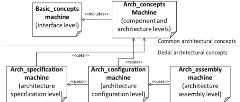
4.2 Formalization of the Dedal architectural model . . . 55
4.2.1 Formalization of the common architectural concepts . . . 57
4.2.2 Formalization of Dedal architectural concepts . . . 60
4.2.3 An illustrative example: B formal specifications of the Home Automa-tion Software . . . 62
4.3 Intra-level rules . . . 63
4.3.1 Intra-level component rules . . . 63
4.3.2 Intra-level architecture consistency . . . 71
4.4 Inter-level rules . . . 75
4.4.1 Inter-level component rules . . . 75
4.4.2 Inter-level architecture coherence . . . 78
4.5 Conclusion . . . 83
5 A formal approach to three-level software architecture evolution 85 5.1 The evolution management model . . . 86
5.1.1 The architectural model (Group 1) . . . 86
5.1.2 The architectural change (Group 2) . . . 90
5.1.3 The Evolution Manager System (Group 3). . . 91
5.1.4 Synthesis . . . 95
5.2 Evolution management approach . . . 95
5.2.1 The overall approach. . . 96
5.2.2 The search algorithm. . . 97
5.3 Conclusion . . . 101
6 Implementation and experimentation: The DedalStudio tool suite 103 6.1 Overview of DedalStudio . . . 104
6.2 Implementation . . . 105
6.2.1 Architecture modeling (DedalModeler ) . . . 105
6.2.2 Formal models generation (FormalDedalGenerator ). . . 108
6.2.3 Architecture analysis and evolution (DedalManager ) . . . 110
6.2.4 Validating architecture evolution (DedalChangeParser ) . . . 112
6.3 Experimentation and evaluation. . . 112
6.3.1 Experimentation . . . 112
6.3.2 Performance evaluation . . . 118
6.4 Conclusion . . . 121
7 Conclusion and future work directions 123 7.1 Contributions . . . 123
7.1.1 Conceptual contributions . . . 124
7.1.2 Technical contributions . . . 124
7.1.3 Applicative contributions . . . 125
7.2 Limitations and future work directions . . . 126
7.2.1 Conceptual perspectives . . . 126
7.2.2 Technical perspectives . . . 127
7.2.3 Applicative perspectives . . . 128
7.2.4 Threats to validity and experimental perspectives. . . 128
A Formal Dedal specifications (Home Automation Software Example) 129 A.1 Basic concepts Machine . . . 129
A.2 Arch concepts Machine . . . 136
A.3 Arch specification Machine . . . 141
A.4 Arch configuration Machine . . . 146
A.5 Arch assembly Machine . . . 153
B EvolutionManager machine 161
C R´esum´e en fran¸cais 181
2.1 The waterfall process model . . . 9
2.2 Component-Based Development Process . . . 11
2.3 Component interfaces (adapted from [Sommerville, 2010]) . . . 14
2.4 Staged process model for evolution [Bennett and Rajlich, 2000] . . . 18
2.5 Reuse development process [Zhang, 2010] . . . 21
2.6 The Dedal architecture levels . . . 23
3.1 Evolution process in C2-SADEL [Oreizy and Taylor, 1998] . . . 30
3.2 Unanticipated changes management in Darwin [Kramer and Magee, 1990] . . . 31
3.3 The architecture of Plastik [Joolia et al., 2005] . . . 32
3.4 Runtime architecture model [Hansen and Ingstrup, 2010]. . . 33
3.5 SAEV meta-model [Oussalah et al., 2005] . . . 34
3.6 Architecture abstraction levels supported by SAEV [Sadou et al., 2005] . . . . 34
3.7 Structure of Evolution Contracts [Tibermacine et al., 2006] . . . 37
4.1 Relations kinds in Dedal . . . 55
4.2 Modularization of Dedal formalization . . . 56
4.3 The architecture descriptions of HAS . . . 62
4.4 Example of component substitutability . . . 64
4.5 Example of name inconsistency . . . 72
4.6 Interface inconsistency . . . 73
4.7 Examples of interaction inconsistencies . . . 74
4.8 Inter-level component relations . . . 75
4.9 Example illustrating two realization cases . . . 76
4.10 Relations between architecture abstraction levels . . . 79
5.1 The evolution management model (ecore) . . . 87
5.2 EMS workflow . . . 92
5.3 Multi-level evolution management process . . . 96
6.1 The architecture of DedalStudio . . . 104
6.2 The Dedal meta-model (ecore) . . . 106
6.3 The interface of DedalModeler . . . 107
6.4 Configuration diagram editor . . . 107
6.5 Embedded textual editor. . . 108
6.6 The translation approach . . . 109
6.7 Example of mapping between meta-classes and B . . . 109
6.8 Evolution plan view . . . 111
6.9 HAS specification . . . 113 ix
6.10 HAS configuration . . . 113
6.11 HAS assembly. . . 114
6.12 Evolving the HAS specification . . . 114
6.13 Evolving the HAS configuration. . . 114
6.14 Change propagation to the HAS assembly . . . 115
6.15 Evolving the HAS configuration. . . 116
6.16 Change propagation to the HAS specification . . . 116
6.17 Change propagation to the HAS assembly . . . 116
6.18 Evolving the HAS assembly . . . 117
3.1 Classification of existing evolution approaches . . . 40
3.2 Comparison of formal modeling languages . . . 50
4.1 B specifications related to interfaces . . . 58
4.2 B Specification of the underlying architecture concepts . . . 59
4.3 B model of the specification level . . . 60
4.4 B specification of the configuration level . . . 61
4.5 B specification of the assembly level . . . 62
4.6 An extract of the B model of the HAS at specification level . . . 63
5.1 Summary of model manipulation operations . . . 89
5.2 The EvolutionManager machine. . . 92
5.3 The schema of an evolution rule. . . 94
5.4 Evolution rule at configuration level . . . 94
6.1 Test parameters for ProB . . . 119
6.2 Test parameters for the evolution-solver algorithm . . . 120
6.3 Performance evaluation . . . 121
Introduction
This introductory chapter briefly presents the context of this thesis, the addressed problematic, our proposal and the organization of the dissertation.
Contents
1.1 Context of Component-Based Software Engineering . . . 1
1.2 Problematic of architecture evolution in CBSD processes . . . 2
1.3 Thesis proposal and contributions . . . 3
1.4 Dissertation outline . . . 4
1.1
Context of Component-Based Software Engineering
Software engineering has greatly evolved since its early days due to the increasing complexity of software systems and the rising need to produce and maintain software cost-effectively. Component-Based Software Engineering (Cbse), a sub-discipline of software engineering, is one of the most promoted development trends that addresses these requirements. Emerged in late 1990s, Cbse promotes an approach to software development centered on effective component reuse [Sommerville, 2010]. It provides methods, models and guidelines to help and improve Component-Based Software Development (Cbsd). The principle of Cbsd is to build software systems by assembling pre-developed and decoupled components stored in software repositories (often referred to as Off-The-Shelf (OTS) components) instead of building all parts from scratch. This approach has the benefit to significantly decrease development cost and time-to-market without giving up quality [Crnkovic,2002].
Central to Cbsd are software architectures. They describe the high-level structure of the software system and expose the dimensions along which it is expected to evolve [Garlan,
2000]. An architecture model lists the constituent elements of the system and the way they 1
are connected together. It captures the design decisions of the software and enables to reason about its evolution. As the complexity of software systems increases, the focus of software development reorients from code to architectures [Shaw and Garlan,1996]. Evolving software architectures avoids to delve into low-level source code which is harder to understand and modify [Georgas et al.,2006].
While Cbse has greatly evolved since its emergence, some issues such as reuse, complexity and maintenance [Crnkovic,2003] are still challenging today. In particular, managing architecture evolution [Breivold et al.,2012] in Cbsd processes is a serious issue.
1.2
Problematic of architecture evolution in CBSD processes
Managing architecture evolution in Cbsd processes is non trivial. Indeed, throughout their whole lifecycle, software systems are subject to several changes to correct bugs, improve per-formance and quality, or be adapted to their host environment. While unavoidable, software changes may alter the system’s architecture leading to several inconsistencies. If not analyzed and handled carefully, architecture inconsistencies engender the loss of evolvability of the soft-ware and lead to its degradation and phase-out. A famous problem is softsoft-ware architecture erosion [de Silva and Balasubramaniam,2012,Perry and Wolf,1992]. It arises when modifica-tions of the software implementation violate the design principles captured by its architecture. While a lot of work has been dedicated to architectural modeling and software evolution in general, there still is a lack of foundations and techniques to manage architecture evolution in Cbsd processes and in particular to tackle architecture inconsistencies notably erosion. Indeed, existing approaches to architecture evolution hardly support the whole life-cycle of component-based software (i.e., design, implementation and deployment). Changes are usually applied at architectural level and then mapped on one-way to implementation (source code) and runtime. The problem of such approaches is that they do not guarantee the traceability of design decisions since the links between design, implementation and deployment are not elucidated. This limits to determine the impact of software changes on architectural decisions across the whole development stages. Notably, dynamic changes (i.e., at runtime) are not fully dealt with since changes are propagated only on one-way (from design to runtime) but not on the opposite way (from runtime to design), hence increasing the risk of erosion and its consequences (i.e., loss of evolvability, degradation and phase-out).
1.3
Thesis proposal and contributions
To increase confidence in reuse-centered, component-based software systems, software archi-tectures must support change at any step of Cbsd (i.e., specification, implementation and deployment). All architecture descriptions must remain consistent after changes and whatever part of the architectural description changes affect, their effects have to be propagated to the other parts.
This thesis proposes an approach to improve the evolution management activity in component-based software development processes. The approach is component-based on Dedal [Zhang et al., 2010,
2012], an Architecture Description Language (Adl) that explicitly separates software archi-tecture descriptions into three abstraction levels: specification, configuration and assembly. These abstraction levels respectively correspond to three major steps of component-based de-velopment (design, implementation and deployment) and keep the traceability of architectural decisions across the whole development process.
The Dedal three architecture abstraction levels present a convenient support for managing architecture evolution in Cbsd. We are confronted to the following research questions in order to establish the evolution management approach:
• What kind of relations should be made explicit between the three architecture abstraction levels to trace the design decisions all along Cbsd?
• What architecture properties should be defined to avoid architecture inconsistencies and erosion in particular?
• How to enable architectural change and control its impact on the three architecture abstraction levels?
• How to enable automated architecture analysis and evolution?
This thesis answers these questions through two main contributions.
The first contribution consists in a type theory for Dedal that formally defines its semantics and the relations between the three architecture abstraction levels. On the one hand, we define intra-level architecture consistency properties to ensure the well-formedness of architecture definitions at any abstraction level. On the other hand, we define inter-level architecture coherence properties to guarantee the traceability of architectural decisions across the three architecture abstraction levels. To enable automated architecture analysis, the type theory is formalized in B [Abrial,1996], a set-theoretic and first-order predicate language.
The second contribution consists in an evolution management model and a formal approach to deal with architectural change in Cbsd processes. The approach enables to determine the level of change, analyze its impact and plan its execution in order to preserve architecture consis-tency and coherence properties. Evolution plans are constituted of sequences of architecture change operations calculated using a search-based strategy solver. Instead of using general-purpose solvers, we propose our own solver with specific heuristics to automatically calculate evolution plans according to our approach. This could significantly improve calculation time, especially when the complexity of architecture models increases.
Finally, we undertake an experimentation to demonstrate the feasibility of our approach. It consists in the experimentation of three evolution scenarios, each addressing a change at a different abstraction level. For that purpose, we have implemented DedalStudio, a Case (Computer-Aided Software Engineering) tool that supports Dedal architecture modeling and evolution management. The tool integrates the specific solver to generate evolution plans. An evaluation of its performance is also presented.
1.4
Dissertation outline
The dissertation is organized as follows:
• Chapter2 introduces the context of this thesis, namely the Cbse and software architec-ture fields and their issues. It then presents the Dedal Adl.
• Chapter3 establishes two state-of-the-art studies related to this thesis. The first study surveys a number of existing approaches to architecture evolution and highlights their limits. The second study surveys five formal modeling languages including B and com-pares them in terms of expressiveness and tool support. This study argues our choice for the B modeling language to support our approach.
• Chapter 4 introduces the type theory underlying the Dedal architectural model and defines the rules to check architecture consistency and coherence between architecture definitions at all abstraction levels.
• Chapter5 presents the evolution management model, its associated approach to auto-matically handle architectural change throughout the whole component-based software lifecycle and the evolution-solving algorithm enhanced with heuristics.
• Chapter 6 presents the implementation of DedalStudio tool suite supporting our ap-proach, demonstrates its feasibility on three evolution scenarios and gives an evaluation of the proposed solver.
• Chapter 7 summarizes our contributions, discusses the limitations of our approach and proposes future work directions.
Context of component-based
software engineering and software
architectures
As mentioned in the introductory chapter, this thesis contributes to the field of Component-Based Software Engineering (Cbse) and more precisely addresses the problematic of architec-ture evolution in reuse-intensive, component-based development processes. Thus, this chapter introduces in more details the context of Cbse and software architectures. Section 2.1 gives the principles of Cbse, compares the component-based software development (Cbsd) process with traditional software development processes and agile methods. Section 2.2 introduces the concepts and definitions related to software architectures and finally Section2.3 presents Dedal, an architecture model tailored for Cbsd processes.
Contents
2.1 Component-Based Software Engineering . . . 8
2.1.1 Component-based software life-cycle . . . 8
2.1.2 Discussion . . . 12 2.2 Software architectures . . . 13 2.2.1 Basic concepts . . . 13 2.2.2 Architecture modeling . . . 15 2.2.3 Architecture evolution . . . 17 2.2.4 Architecture analysis. . . 19
2.3 The Dedal architecture model . . . 21
2.3.1 The Dedal architecture specification level . . . 22
2.3.2 The Dedal architecture configuration level . . . 23
2.3.3 The Dedal architecture assembly level . . . 24
2.4 Conclusion . . . 25
2.1
Component-Based Software Engineering
Component-Based Software Engineering is the sub-discipline of software engineering that con-cerns the development of software systems making considerable use of components. It provides methods, models and guidelines for the developers of component-based systems [Pree,1997]. Cbse emerged in the late 1990’s as an approach centered on effective software reuse [ Som-merville, 2010]. The principle is to produce software systems from already existing compo-nents instead of developing all parts from scratch. The main motivations of such approach is to reduce development cost and time to market, meet rapidly emerging customer demands and increase software reliability and maintainability [Szyperski,2002]. Cbse has quickly grown up and becomes recognized as an important sub-discipline of software engineering. There are several reasons behind this fast emergence. First, software systems are becoming increasingly complex and provide more functionality. By using components, it is possible to produce more functionalities with the same investment of time and money [Pree,1997]. Second, traditional approaches failed to support reuse. For instance, single object classes are too detailed and specific whereas components are more abstract and can be considered to be standalone service providers [Sommerville,2010]. Third, systems need to be constantly updated and maintained to respond to new requirements. This need requires a support for easy additions. Heineman and Councill summarize the three major goals of Cbse [Heineman and Councill,2001]:
• To support the development of components as reusable entities;
• To provide support for the development of systems as assemblies of components; • To facilitate the maintenance and upgrading of systems by customizing and replacing
their components.
Although these goals are very promising, it has been shown that achieving them in practice is very hard and the process of improving reuse has been long and laborious [Pree,1997]. In particular, evolving component-based systems in practice is not that easy, especially after the deployment phase. A deep understanding of the component-based software life-cycle is hence required to better highlight the issues of Cbse.
2.1.1 Component-based software life-cycle
This section outlines traditional software development processes and agile methods then presents the component-based development process.
2.1.1.1 Traditional software development processes
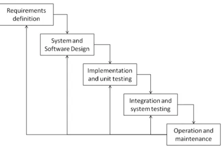
The waterfall Process model. Most of traditional software development approaches ad-here to the waterfall process model proposed by Royce in 1970 [Royce, 1987]. The principal stages of the waterfall model (cf. Figure2.1) map to the following fundamental development activities [Sommerville,2010]:
• Requirements definition: This step consists in identifying the system’s functionalities, constraints and goals by consulting system users. A more detailed and possibly formal specification of the system is then defined.
• System and software design: This step consists in describing a conceptual and tech-nical solution to realize the software. An overall system architecture is established. • Implementation and unit testing: During this step, a set of program units are
realized according to the software design. Unit testing ensures that each unit meets each specification.
• Integration and system testing: This step consists in integrating all the individual program units into a whole system, performing complete tests to ensure that system requirements are met, and delivering the product to the customer.
• Operation and maintenance This step is the post-delivery phase. It involves fixing bugs which were not yet discovered in earlier stages, improving the implementation of system units and including new services as new requirements might need to be considered.
Figure 2.1: The waterfall process model
The waterfall model proposes a clear separation between the different stages of software devel-opment. Its main advantage is that phases do not overlap and documentation is produced at
each stage [Sommerville,2010]. The waterfall model is more suitable for small projects where requirements are very well understood. However, such partitioning of software development makes it difficult to respond to changing customer requirements. Indeed, commitments must be made at an early stage in the process while results are produced very late [Sommerville,
2010].
2.1.1.2 Agile methods
Agile methods emerged in 1990s to cope with the disadvantages of traditional process models. They support rapid software development and are more amenable to requirement change. Agile methods were primarily designed to support the development of business applications and quickly deliver working software to customer in an iterative manner [Sommerville,2010]. In 2001, a group of practitioners established a consensus -called the manifesto of agile software-that sets the values and principles of agile methods 1. The manifesto advocates these four values:
• Individuals and interactions over processes and tools. • Working software over comprehensive documentation. • Customer collaboration over contract negotiation. • Responding to change over following a plan.
Agile methods are iterative and focus on incremental development. They actively involve customer in the development process for feedback and facilitate requirements change even after software delivery [Sommerville,2010].
The main disadvantage of such methods is that they depend too much on human personalities (team developers, customers). Developers are not always willing to support the pressure of such intense processes and customers are not always willing to spend the time necessary to give useful feedback [Sommerville, 2010]. Moreover, prioritizing changes may become a difficult task when the system involves many stakeholders since each stakeholder sees priorities differently [Sommerville, 2010]. Agile methods are more suitable for small and medium-sized systems with no associated risks than large, complex and critical systems [Sommerville,2010].
2.1.1.3 Component-based software development process
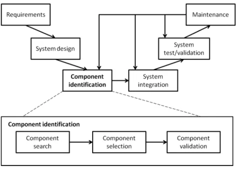
The main idea of Cbsd is building systems from pre-existing components. This entails two consequences on the software development process [Crnkovic et al., 2006] (cf. Figure 2.2).
1
First, software development (so called development by reuse) is separated from component development (so called development for reuse). Therefore, components are supposed to be already developed when the software development process starts. Second, a component iden-tification step [Sommerville,2010] is included in the development process. In the remainder, we detail the principal stages of Cbsd.
Figure 2.2: Component-Based Development Process
Requirements. In component-based approach, requirements can be defined as abstract component types describing the funtionalities of the system. Defining requirements in a component-based approach must consider that, if possible, resulting specification has to be fulfilled by available software components. If not, either new components have to be devel-oped or requirements have to be negotiated and modified to use existing components [Crnkovic et al.,2006].
System design. The design phase consists in defining a complete system architecture with refined component types to be fulfilled with existing software components. Similar to the requirement phase, the design phase is strongly related to the availability of components.
Component identification. Component identification step is specific to Cbsd. It replaces the implementation phase in traditional development processes. Component identification consists in three sub activities:
• component search: This activity consists in browsing component repositories (such as Off-The-Shelf (OTS) components) and identify the set of candidate components that are the most qualified to fulfill system design.
• component selection: This activity consists in deciding which component composition provides the best coverage of requirements [Sommerville, 2010]. Selection might be more complex than search since finding a perfect matching between components and requirements is often unrealistic.
• component validation: Once components are selected, the architect has to test and vali-date if they behave as advertised. This activity corresponds to unit testing in traditional development processes and can be omitted if the component provider is trustworthy.
System integration. This step consists in downloading component from repositories, de-ploying them into a component container and assembling them into an executable system architecture.
System validation. Like in traditional development processes, this step is performed to ensure that all system requirements are met.
Maintenance. In a component-based approach, maintenance is achieved by checking the availability of new components or new versions of available components. This step maps back to the component identification step to search for updates.
2.1.2 Discussion
Cbse presents a reuse-based approach to software development. While its associated devel-opment process (Cbsd) provides numerous benefits compared to the traditional approaches (e.g., reducing complexity and time to market, separating concerns, improving software qual-ity, etc.), Cbsd also presents some issues. First, reuse is not such easy since finding trusty software components that perfectly match with system requirements is not always possible. Revising and adapting requirements and/or developing new software components that fit to the system’s specification is often necessary. Second, managing software evolution in Cbsd processes is a complex task. Indeed changes may affect software at any step of its life-cycle (e.g., new requirements, new software component versions, component failure, etc.). The im-pact of change might take high extents compromising thus the whole system, if not analyzed and handled carefully. We address this issue in chapter 5.
Crucial to Component-Based Software Engineering are software architectures. Next section introduces the definitions, concepts and activities related to software architectures.
2.2
Software architectures
This section introduces the basic concepts of software architectures as well as their related activities; architecture modeling, architecture evolution and architecture analysis.
2.2.1 Basic concepts
Software architectures are the blueprint of software system’s construction and evolution [ Tay-lor et al., 2009]. They describe the high-level structure of the software system and expose the dimensions along which it is expected to evolve [Garlan, 2000]. A software architecture captures the principal design decisions made about the system such as its structure, func-tional behavior, interaction and non-funcfunc-tional properties. Perry and Wolf [Perry and Wolf,
1992] define three types of architectural elements that may be consolidated into two major architectural concepts; components and connectors:
• Processing elements are components that process the data.
• Data elements are components that contains data to be processed.
• Connecting elements are mediators that hold connections between the different compo-nents.
In the remainder, we define and detail the concepts of components and connectors.
2.2.1.1 Components
Several definitions about software components exist in the literature. We give two widely cited definitions that say the essential about what a component is. The first definition was given by Taylor et al. [Taylor et al.,2009] as follows:
“A software component is an architectural entity that (1) encapsulates a subset of the system’s functionality and/or data, (2) restricts access to that subset via an explicitly defined interface, and (3) has explicitly defined dependencies on its required execution context.”
In other words, a component is a unit of computation that encapsulates data, provides services to process it and may require services from other components for its execution. Depending on the architecture, a component may be as simple as an operation or as complex as an entire system. The second definition is the one of Clemens Szyperski [Szyperski,2002] who defined a software component as follows:
“A software component is a unit of composition with contractually specified inter-faces and explicit context dependencies only. A software component can be deployed independently and is subject to composition by third parties.”
Roughly said, a component is a ”black box” where code and implementation details are entirely hidden and data is accessed only via interfaces. Components hence adhere to the software en-gineering principles of encapsulation, abstraction and modularity. They are decoupled entities developed for reuse. A component comprises three parts: a set of interfaces, an implementation and a specification.
Interfaces. An interface is the communication point that manages the interaction of com-ponent with its environment, i.e., the other comcom-ponents [Szyperski, 2002]. Components are made abstract thanks to their interfaces that hide the implementation details and ease reuse. Interfaces can be either provided or required (cf. Figure 2.3):
• A provided interface exposes the set of services provided by the component to other components. The communication point enables to receive service invocations from other components.
• A required interface defines the services required by the component from other compo-nents. The communication point enables to send service requests to other compocompo-nents.
Figure 2.3: Component interfaces (adapted from [Sommerville,2010])
Implementation. On the contrary, an implementation refers to the concrete and internal definition of a component (white box), i.e., its source code. Once the component is developed, its implementation is hidden and decoupled thanks to interfaces. Components can then be (re)used to build architectures without any required knowledge about their inner implemen-tation.
Specification. The component specification refers to the definition (type) of its interfaces [Crnkovic,
2002]. At the beginning, an interface specification was limited to its syntactical definition, i.e., a set of operation signatures where each signature includes a name and a set of parame-ters. Several Idls (Interface Definition Languages) were then proposed to specify component
interfaces. Later, Meyer introduced the notion of contract [Meyer, 1992] that extends the syntactical definition with behavior (by adding pre- and post-conditions on the interface oper-ations). The contract concept was in turn enriched to include additional characteristics such as synchronization (the order of operations) and quality of service [Beugnard et al.,1999,2010].
2.2.1.2 Connectors
Another fundamental aspect of software systems is managing interaction between its building blocks, i.e., components. While software components implements the functionalities of the sys-tem, software connectors bind components together and act as mediators between them [Taylor et al., 2009]. This separates the computation concern handled by components from the in-teraction concern managed by connectors, hence strengthening reuse. Inin-teraction may even become more challenging than selecting appropriate components. This is often the case when systems are built from large numbers of complex components distributed across multiple hosts and updated over long time periods [Taylor et al., 2009]. A software connector can provide multiple services in the architecture. Mehta et al. identify eight types of software connectors depending on the services they realize [Mehta et al.,2000]: procedure call, event, data access, linkage, stream, arbitrator, adapter and distributor.
Connectors can be explicitly represented as specific components with two communication points; the provided connector end and the required connector end (e.g., C2SADEL [ Med-vidovic et al.,1999], Wright [Allen and Garlan,1997]). Each connector end is the counterpart of the connected component interface. Connectors can also be implicitly represented by a simple link binding two opposite interfaces of two different components (e.g., Darwin [Magee et al.,1995]).
2.2.2 Architecture modeling
Architecture modeling is the activity of documenting one or several aspects of a system’s archi-tecture using a particular notation. An architectural model is hence an artifact that captures some or all of the design decisions comprised in the software architecture [Taylor et al.,2009]. Architecture models are sometimes referred to as architecture descriptions. An architectural modeling notation is a language or means used to model software architectures. In the re-mainder, we focus on architecture modeling notations and namely, Architecture Description Languages.
2.2.2.1 Level of formalism of architectural modeling notations
Available notations range from the informal to the highly formal. The choice of a modeling architectural notation depends on the stakeholders to which models are addressed. Taylor et al. [Taylor et al.,2009] classify architectural modeling notations into three categories according to their level of formalism:
• Informal models: A model is said to be informal when it does not have a formally defined syntax. Usually, informal models are captured in boxes-and-lines diagrams and are intended for non-technical stakeholders such as managers and system customer. • Semi-formal models: A semi-formal model has a formally defined syntax and is mostly
used for both technical and non-technical system stakeholders. It tries to strike a balance between precision and formalism on one hand, and expressiveness and understandability on the other. A widely spread example of semi-formal languages is Uml [UML,2013]. Unlike informal boxes-and-lines notations, Uml is standardized and its notation obey to a common specification.
• A formal model has formally defined semantics in addition to a formally defined syntax. Formal models are typically intended for the system’s technical stakeholders. They are used to address the most critical aspects of a system and are amenable to automated analysis [Taylor et al.,2009].
2.2.2.2 Architecture Description Languages
An Architecture Description Language (Adl) is a language dedicated to architecture model-ing. It provides features and specific constructs to express the basic concepts of a software architecture i.e., components and their connections. The definition of an Adl has long been ambiguous. Consensus on this definition was established by Medvidovic et al. as they surveyed a large number of Adls and identified their common properties [Medvidovic and Taylor,2000]. The following definition can hence be given to an Adl [Medvidovic,2006]:
“An architecture description language is a language that provides features for mod-eling a software system’s conceptual architecture, distinguished from the system’s implementation. An Adl must support the building blocks of an architectural de-scription.”
An Adl must hence be able to express components and their interfaces, connectors (implicitly or explicitly) and configurations (i.e., the topology of the architecture). First-generation Adls
were domain-specific. Examples include C2-SADEL [Medvidovic et al.,1999] for the design of concurrent systems and Wright [Allen and Garlan,1997] and Darwin [Magee and Kramer,
1996] for the design and analysis of distributed architectures. Later, attempts to unify Adls and make them general-purpose were made. ACME [Garlan et al., 1997] was designed for such purpose. It consists in a common interchange description language that offers annotation facilities to support architecture descriptions in other languages. Another relevant example is xAdl 2.0 [Dashofy et al., 2001]. It was designed to support various types of systems. The particularity of xAdl 2.0 resides in its extensibility since it is XML-based. It offers then an easy way for architects to adapt its use to any kind of architectures.
Adls can also be used to perform architecture analysis and support architecture evolution. Chapter3 surveys a number of approaches that rely on Adls to support such activities.
2.2.3 Architecture evolution
As software ages, its architecture must evolve to tackle all the changes that arise during the software life-cycle. Architecture evolution is considered as one of the most challenging tasks of component-based software engineering. To better identify the motivations and issues of architecture evolution, this section gives a quick overview of software evolution in general and architecture-centric evolution in particular.
2.2.3.1 Software evolution
Since the early years of software engineering, there was an awareness that the most costly and difficult part of software development is its maintenance phase. In a study conducted by Lientz and Swanson et al. in the 70’s [Lientz et al., 1978], it has been proven that mainte-nance costs represent about 60% of the overall costs of software production. Maintemainte-nance as shown in the waterfall development process (cf. Figure2.1) is the final phase of the life-cycle of a software system that comes after its deployment to fix bugs and bring some adjust-ments. This classical view has long governed in practice and is still widely used in industry today [Mens and Demeyer,2008]. It also became a part of IEEE 1219 Standard for software maintenance [IEEE1219-1998,1998] which defines maintenance as follows:
“Software maintenance is the modification of a software product after delivery to correct faults, to improve performance or other attributes, or to adapt the product to a modified environment.”
This process model is too strict and not flexible enough to deal with evolution. Indeed, requirements continue to change during the entire software life-cycle. It is hence unrealistic
to assume that the requirements are all known and fixed before starting software design. Moreover, knowledge gained during the later phases may need to be fed back to the earlier phases [Mens and Demeyer, 2008]. The limitation of this process model was noticed a long time ago and a particular interest to software evolution was started by Manny Lehman when he stated the famous ”Laws of software evolution” [Lehman,1984]. Lehman defined software evolution as follows:
“Software evolution is the collection of all programming activities intended to gen-erate a new version of some software from an older operational version. If these activities can be performed at runtime without the need for system recompilation or restart, it becomes dynamic software evolution.”
The particularity of Lehman’s definition is that it deals with the evolution of systems not just the evolution of code. Later research on software evolution resorted to evolving software at the architectural level rather than source code.
Several evolutionary process models were proposed to tackle the limitations of the waterfall process model. Among the most famous models is the staged process model of Bennett and Rajlich [Bennett and Rajlich,2000] presented in Figure2.4.
Figure 2.4: Staged process model for evolution [Bennett and Rajlich,2000]
The Bennett and Rajlich model has the particularity to explicit the inevitable problem of software aging [Parnas,1994]. After the initial development, the software is subject to several changes that lead to its degradation. When there is a loss of evolvability, servicing stage starts to keep software running up by applying small patches (minor changes) [Mens and Demeyer,
2008]. When the servicing stage becomes too hard and costly, the software enters the phase out stage and then is closed down.
2.2.3.2 Architecture-centric evolution
One of the major assets of software architecture is undoubtedly its support for evolution. As stated in the most common definitions, a software architecture is also the backbone of software evolution. It exposes the dimensions along which the system is expected to evolve [Garlan,
2000]. Reasoning about evolution at the architectural level enables a better understanding of change and allows a better estimation of modifications costs. Evolving software architectures avoids to delve into low-level source code which is harder to understand and modify [Georgas et al., 2006]. Indeed, evolution is resorted out to manipulating the constituent parts of the software and their connections as for instance replacing, deleting or adding components. Nevertheless, architecture evolution presents several issues. Software architectures may be altered due to changes leading to several inconsistencies (or mismatches). Architecture mis-matches engender loss of evolvability and lead to software degradation (cf. Figure2.4). Avoid-ing architectural mismatches is one of the major challenges of Cbse. As argued by Garlan et al., the difficulty of reuse comes essentially from architectural mismatches that arise due to several changes that affect software [Garlan et al., 1995,2009]. Next section discusses in more details architecture mismatches and chapter5presents our architecture evolution model to deal with such inconsistencies.
2.2.4 Architecture analysis
Architecture analysis can be defined as the activity of discovering important system properties captured by the system’s architecture models [Taylor et al.,2009]. It relies on rigorous formal models and helps the early detection of inappropriate or incorrect design decisions. Architec-ture analysis presents an efficient way to anticipate architecArchitec-ture inconsistencies that may arise during software evolution.
Architecture inconsistencies. Taylor et al. [Taylor et al.,2009] define consistency as an internal property intended to ensure that different elements of an architectural model do not contradict one another. They cite five examples of inconsistencies that may occur in an architectural model:
• Name inconsistencies concern the names of components or their constituent elements such as exported services. Inconsistency may occur when multiple elements have the same name and the wrong one is accessed or when attempting to access a non-existent element.
• Interface inconsistencies can result from name inconsistencies when the name of a required service does not match with another component’s provided one. Interface in-consistencies concern also type mismatches between a required and a provided interface. Notably, when the parameter types of the required service or their return types do not match with the provided one according to the type system followed by the architectural model.
• Behavioral inconsistencies can occur between two components that satisfy name and interface consistencies but have services which behaviors do not match.
• Interaction inconsistencies occur when the interaction protocol between two compo-nents is violated. An example is the order of accessing their services.
• Refinement inconsistencies concern multiple levels of abstraction of a software sys-tem description and occur when architectural design decisions are omitted, changed or violated in a description according to a more abstract one.
Apart from the inconsistencies identified by Taylor et al., there are two famous architecture mismatches highly cited in the literature which are erosion and drift introduced by Perry and Wolf in 1992 [Perry and Wolf, 1992]. These architecture problems have gained a lot of interest several years ago and are now recognized as major issues of architecture-centric evolution [de Silva and Balasubramaniam,2012]. Erosion can be defined as the violation of design decisions described at a higher abstraction level by its lower abstraction level whereas drift can be defined as the introduction of new design decision at a lower abstraction level that are not included or implied by its higher abstraction level. Given these definitions, erosion and drift might be considered as refinement inconsistencies. Some other definitions refer to these terms in a more generalized way such as architectural degeneration [Hochstein and Lindvall,
2005] or architectural decay [Riaz et al.,2009]. De Silva et al. [de Silva and Balasubramaniam,
2012] proposed the following definition of architecture erosion:
“Erosion is the phenomenon that occurs when the implemented architecture of a software diverges from its intended architecture.”
This definition is interesting because it highlights the relation between two architecture levels, i.e., the intended architecture and the implemented architecture. Taylor et al. use the terms prescriptive architecture and descriptive architecture [Taylor et al.,2009] to respectively denote these levels. Few work however has been dedicated to expliciting these two levels and studying their relationship. To better control erosion in Cbse processes, the intended architecture and the implemented architecture must be explicitly described. Additionally, the runtime archi-tecture level must be taken into account since erosion can be engendered by dynamic changes.
The problem of erosion can also be seen in the opposite way, i.e., the intended architecture diverges from its implemented architecture. This often happens when new requirements are included in the system’s specification but some of them are not implemented. Zhang, in her thesis [Zhang,2010], gives the name pendency to this problem and defines it as the introduc-tion of new design decisions into a higher architecture level that are not implemented by its lower architecture level. Next section discusses the abstraction levels that must be elucidated in Cbsd process to foster reuse and better control architecture inconsistencies that may arise during architecture-centric evolution.
2.3
The Dedal architecture model
Zhang proposes a new vision of Cbsd [Zhang,2010] that explicits the architecture descriptions produced at each development step (cf. Figure2.5).
Figure 2.5: Reuse development process [Zhang, 2010]
The proposed process focuses on three development steps: specification (or design), implemen-tation and deployment. After a classical requirement analysis, architects design an architecture specification that defines which services should be supplied by components and how compo-nents should be connected to meet requirements. The architecture specification corresponds to the architecture as intended. The next step consists in creating an architecture configuration that implements the specification. During this step architects select suitable concrete compo-nents that match those specified in the previous step and compose them to realize a complete architecture. The architecture configuration corresponds to the architecture as implemented. The final step consists in instantiating and deploying the architecture configuration. The
corresponding model is called the architecture assembly and represents the architecture as deployed.
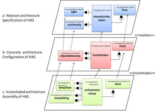
Dedal [Zhang et al.,2010,2012] is an Adl and architecture model that supports such process. It explicitly separates software architecture definitions into three abstraction levels: speci-fication, configuration and assembly. To illustrate the concepts of Dedal, we introduce the Home Automation Software (Has) example that manages comfort scenarios. Here, it auto-matically controls the building’s lighting in function of the time. For this purpose, we propose an architecture with an orchestrator component that interacts with the appropriate devices to implement the desired scenario. In the remainder, we present the Dedal three architecture levels. Figure 2.6is recalled to illustrate each architecture abstraction level corresponding to the Has example.
2.3.1 The Dedal architecture specification level
The architecture specification level corresponds to the design step of the Cbsd process. It defines the functional requirements of the software system and gives an abstract view of its constituent elements. The design decisions to be taken at this level consist in identifying the types of components which will be (re)used to perform the required functionalities. These abstract component types are called component roles.
Component roles. Specifying an architecture consists on defining component roles that represent the expected fucntionalities to be provided by available components. A component role only declares the functionalities (as a set of interface specifications). This abstract def-inition allows a wider set of components to match the specification and be later selected to implement the architecture. Hence, component roles are used as a guide to help the search for concrete existing component in the next step.
Figure 2.6-a shows an example of architecture specification. It is constituted of the Home-Orchestrator component role that manages the building’s lighting using both Light and Lu-minosity component roles, in function of time by calling the Time component role.
Figure 2.6: The Dedal architecture levels
2.3.2 The Dedal architecture configuration level
The configuration architecture level corresponds to the implementation step of the Cbsd pro-cess. It describes a concrete implementation of the software system. An architecture configu-ration is defined by the set of components selected during the identification process and that best match with the abstract component types (i.e., component roles) defined in the architec-ture specification. These artifacts are called component classes and their associated types are called concrete component types.
Component classes. Component classes correspond to existing software components stored in repositories (such as OTS components). In Dedal, component classes can either be prim-itive or composite. A primprim-itive component class encapsulates executable code. A composite component class encapsulates an inner architecture configuration (i.e., a set of connected com-ponent classes which may, in turn, be primitive or composite). A composite comcom-ponent class exposes a set of interfaces corresponding to the unconnected interfaces of its inner components. Component classes can also have attributes that enable parametrization.
Concrete component types. A component type gives an abstract representation of a set of component classes. It defines the set of interfaces that a class must hold to be an implementation of this type. Component types are used to classify component classes and
build indexes on the content of component repositories. To search for component classes that can be used to implement an architecture specification, component roles are matched with component types (using classification based on specialization and substitution in a manner similar to Ar´evalo et al. [Aboud et al.,2009,Ar´evalo et al.,2008]).
Figure2.6-b shows an example of architecture configuration. It represents an implementation of Has conforming to the architecture specification shown in Figure2.6-a. The HomeOrches-trator and Time component roles are respectively realized by the OrchesHomeOrches-trator and Clock component classes whereas the Light and Luminosity coomponent roles are both realized by the AdjustableLamp component class. The relations between component classes and compo-nent roles are studied in depth in Chapter4.
2.3.3 The Dedal architecture assembly level
The architecture assembly level corresponds to the deployment step of the Cbsd process. It consists in an assembly of instantiated concrete component selected during the implementation step. These artifacts are called component instances. The architecture assembly describes software at runtime and holds information about its internal state. It lists the instances of the component classes that compose the deployed architecture at runtime and their assembly constraints (such as the maximum number of connected instances).
Component instances. Component instances document how the component classes from an architecture configuration are instantiated in the deployed software. Each component instance has an initial and a current state defined by a list of valued attributes.
Figure2.6-c shows an example of architecture assembly. It represents a possible instantiation of Has. This assembly enables to manage the lighting in two rooms, desk and sitting room, thanks to the two instances of the AdjusatbleLamp component class: lampDesk and lampSitting.
Discussion. Dedal introduces three architecture abstraction descriptions that document the three majors steps of Cbsd process. It helps hence a better understanding of the component-based development activity and provides more flexibility to software design by reuse. It pro-vides an XML-based textual syntax (the Adl) that enables to specify software architectures in three separate architecture descriptions (i.e., specification, configuration and assembly). In this work, we focus on studying the relations between the Dedal architecture levels (e.g., the realizes relation between component roles and component classes) and formally define their semantics to enable architecture analysis and evolution. Therefore, the Dedal Adl syntax is out of the scope of this work and the interested reader may find it in Zhang’s thesis [Zhang,
2.4
Conclusion
This chapter introduced the context of Component-Based Software Engineering and Software Architectures and highlighted the issues of both fields. We draw attention to two main issues. First, reuse is still difficult because fulfilling requirements with existing software components often needs revision and requirement adaptation. Second, managing architecture evolution in Cbsd processes is a complex task because of the several inconsistencies that may alter the archi-tecture (e.g., interface inconsistencies, interaction inconsistencies, erosion, etc.). Changes may intervene at any step of Cbsd, i.e., requirements, implementation or deployment. Therefore, determining and handling the impact of change on the traceability of architecture decisions is also challenging.
This chapter also presented Dedal, a novel architecture model tailored for Cbsd processes. The particularity of Dedal is that it explicitly separates architecture definitions into three abstraction levels (i.e., specification, configuration and assembly) that correspond to there major steps of Cbsd process (i.e., design, implementation and deployment). Therefore, we opt for Dedal to support our approach to architecture evolution management.
Software architecture evolution and
formal modeling languages:
A state of the art
The previous chapter introduced the context of component-based software development and the concepts related to software architectures as they present the blueprint of software system construction and evolution. This chapter addresses the issues of managing software architec-ture evolution. For that, we conduct two studies. In the first study (Section3.1), we survey a number of existing approaches based on architecture-centric evolution and classify them according to a number of criteria we consider crucial to handle evolution in reuse-centered, component-based processes. This study aims to highlight the advantages and limits of exist-ing approaches and to help us set the basis for an alternative approach. In the second study (Section3.2), we survey a number of formal modeling languages and compare them in terms of expressiveness and tool support. This study aims to evaluate the suitability of formal modeling languages to support architecture evolution analysis. This chapter concludes on the choices considered to address the issues of component-based architecture evolution management.
Contents
3.1 Study of existing evolution approaches . . . 28 3.1.1 C2-SADEL . . . 29 3.1.2 Dynamic Wright . . . 29 3.1.3 Darwin . . . 30 3.1.4 ArchWare . . . 31 3.1.5 Dynamic reconfiguration with Plastik . . . 32 3.1.6 Approach of Hansen et al. . . 32 3.1.7 SAEV . . . 33
3.1.8 SAEM . . . 35 3.1.9 Approach of Barnes et al. . . 36 3.1.10 Approach of Tibermacine et al. . . 37 3.1.11 Synthesis and comparison . . . 38 3.2 Formal modeling languages . . . 42 3.2.1 Overview of formal modeling languages . . . 43 3.2.2 Synthesis and comparison . . . 48 3.2.3 Discussion . . . 51 3.3 Conclusion . . . 52
3.1
Study of existing evolution approaches
In this state-of-the-art, we survey a number of approaches addressing the evolution of software architectures. Since the literature about architecture evolution is very abundant, the survey covers the most relevant approaches proposed during the two last decades and that are related to this thesis. In this survey, we try to answer the following questions in order to evaluate existing approaches:
• Is the approach general-purpose or domain-specific?
• What does the approach use as a support to model architectures and manage software evolution?
• What architecture abstraction levels does the approach take into account? And does the approach support multi-level evolution (i.e., top-down evolution and bottom-up evolution).
• What kinds of change operations are possible with the approach? Is there any mechanism to specialize and substitute components?
• What kind of analysis does the approach support? And what kind of formalism is used to perform architecture analysis?
• Is there any tool support for the proposed approach?
In the remainder, we present existing evolution approaches and in Section3.1.11we give their comparison based on the previous questions.
3.1.1 C2-SADEL
Medvidovic et al. [Medvidovic et al.,1999] propose an approach to evolve software architectures based on the C2-style [Taylor et al.,1995]. C2 is a component and message-based architecture style designed to specify GUI (Graphical User Interface) and distributed applications. The ap-proach relies on C2-SADEL (Software Architecture Description and Evolution Language), an Adl for modeling architectures in the C2-style provided with subtyping mechanisms to enable architecture evolution. C2-SADEL separates between component types and component in-stances. Architectures hence can be explicitly modeled at two abstraction levels: a description that contains component types and their connections and another description that contains instances of component types and connectors. However, there is no clear distinction however between abstract component types and concrete ones. C2-SADEL also provides a sub lan-guage for describing changes called AML (Architecture Modification Lanlan-guage). AML allows five change operations: addition (addComponent ), deletion (removeComponent ), connection (weld ), disconnection (unweld ) and replacement (upgrade).
Component subtyping is in the heart of the evolution approach proposed by Medvidovic et al.. The subtyping mechanism is built upon a type theory [Medvidovic et al.,1998] inspired from Object-Oriented subtyping rules. The theory proposes multiple rules for subtyping com-ponents. Depending on the architect’s goal, it is possible to specialize one or multiple aspects of components (i.e., name, interfaces, behavior or implementation). The type theory also enables architecture analysis like type-checking and checking interoperability between two components. The evolution process depicted in Figure3.1enables evolution on one direction. Changes are firstly applied on architectural models. Then, they are reified to synchronize the implementation with architectural models and finally implemented. While the evolution process is complete, it only supports forward evolution. Dynamic changes cannot be captured and propagated to architecture models through a reverse evolution process. Moreover, the approach applies only to C2-style architectures that imposes strict communication rules be-tween components and requires a specific expertise from the architect (e.g., event-based and asynchronous programming, concurrency handling) [Oreizy et al.,1998].
3.1.2 Dynamic Wright
Dynamic Wright [Allen et al., 1998] is an extension of the Wright [Allen and Garlan, 1997] Adl that supports architecture evolution. Wright is basically designed to model and ana-lyze the dynamic behavior of distributed architectures. It provides only one representation to model architectures. An architecture description in Wright (called Style) lists component and connector types as well as their instances. Reuse is not favored since component types are not defined as independent entities. Wright supports architecture analysis thanks to Csp
Figure 3.1: Evolution process in C2-SADEL [Oreizy and Taylor,1998]
(Communicating Sequence Processes) [Hoare,1978], its formal ground. The evolution in Dy-namic Wright is managed by control events. A control event consists in a condition under which the dynamic change is allowed. Control events are grouped into a configuration program that specifies how reconfiguration actions (new, del, attach and detach) will be triggered. The approach based on Dynamic Wright addresses only one level of change (runtime). Moreover, the Adl is domain-specific (distributed architectures) and is based on the Csp notation which makes its use limited to experienced users.
3.1.3 Darwin
Darwin [Magee et al., 1995] is an Adl designed for the specification of the structure of dis-tributed systems. It provides a hierarchical decomposition scheme to define components. Hence, an architecture description in Darwin consists in a root composite component includ-ing a set of component instances and their connections. Basic semantics in Darwin are defined with π-calculus [Milner et al.,1992]. They consist in services (provide and require), bindings (bind ) and primitive components defined as compositions of services. Darwin hence enables analysis and guarantees the correctness of connections.
Darwin provides two mechanisms to deal with anticipated dynamic architecture evolution [Magee and Kramer, 1996]: lazy instantiation and direct dynamic instantiation. Lazy instantiation consists in instantiating a component only when one of its services is invoked. However, in-volved components and the way they are attached must have been specified at design-time. Direct dynamic instantiation allows dynamic structures to evolve in arbitrary ways. Darwin also deals with unanticipated evolution. This process is controlled through a reconfiguration
![Figure 2.4: Staged process model for evolution [Bennett and Rajlich, 2000]](https://thumb-eu.123doks.com/thumbv2/123doknet/7716832.248010/31.893.203.687.630.937/figure-staged-process-model-evolution-bennett-rajlich.webp)
![Figure 2.5: Reuse development process [Zhang, 2010]](https://thumb-eu.123doks.com/thumbv2/123doknet/7716832.248010/34.893.209.692.499.830/figure-reuse-development-process-zhang.webp)
![Figure 3.1: Evolution process in C2-SADEL [Oreizy and Taylor, 1998]](https://thumb-eu.123doks.com/thumbv2/123doknet/7716832.248010/43.893.225.675.118.456/figure-evolution-process-c-sadel-oreizy-taylor.webp)
![Figure 3.4: Runtime architecture model [Hansen and Ingstrup, 2010]](https://thumb-eu.123doks.com/thumbv2/123doknet/7716832.248010/46.893.209.683.192.442/figure-runtime-architecture-model-hansen-ingstrup.webp)
![Figure 3.5: SAEV meta-model [Oussalah et al., 2005]](https://thumb-eu.123doks.com/thumbv2/123doknet/7716832.248010/47.893.155.740.129.406/figure-saev-meta-model-oussalah-et-al.webp)
![Figure 3.7: Structure of Evolution Contracts [Tibermacine et al., 2006]](https://thumb-eu.123doks.com/thumbv2/123doknet/7716832.248010/50.893.122.838.319.642/figure-structure-evolution-contracts-tibermacine-et-al.webp)