SOME ADVICE FOR MIGRATING TO IFC
V. DELFOSSE, J. SCHRAYEN, R. JUCHMES, P. LECLERCQ University of Liège, Liège, Belgium
vincent.delfosse @ ulg.ac.be, john.schrayen @ ulg.ac.be, r.juchmes @ ulg.ac.be, pierre.leclercq @ ulg.ac.be
Abstract. Nowadays, the BIM (Building Information Modeling) paradigm is a central topic in the CAAD community. Next to the commercial solutions, the IFC (Industry Foundation Classes) have emerged as the best open standard candidate for BIM interoperability. Despite the efforts of the community for promoting IFC over the last 15 years, it seems that its practical adoption in real-life projects has been very limited. The goal of this article is to explore how useful IFC can be today and to provide the reader with some advice for an effective adoption of IFC. Over the last year, we have conducted a project aiming at acquiring a sound understanding of IFC. It was made of two complementary investigations. On one hand, we have focused on the commercial modeling tools and the IFC support they were offering. On the other hand, we have focused on the IFC-based software developments. We have developed a tool converting IFC files into a dedicated thermal assessment based model. We will summarize the experience we have acquired in this project into some advice for users migrating to IFC. Our goal is to confront the practical aspects of the IFC developments, with both the theoretical ambitions and the commercial support currently available.
Keywords. Building Information Modeling, Industry Foundation Classes, interoperability.
1. Introduction
The building design process has to be improved to face the new challenges for building at the 21st century: managing increasingly complex buildings, ensuring high standards of comfort and security or controlling the energy consumption of buildings.
To do this, it is necessary to predict accurately as early as possible the performances of the building taking into account the entire life cycle: design, construction operation and demolition. We have for this simulation software
more and more efficient. However these software requires accurate information about the building: technology, material properties, measurements etc. Therefore they need a building model they can query to extract these data. One paradigm being put forward to address this issue is the Building Information Modeling (Eastman et al. 2011).
1.1. BUILDING INFORMATION MODELING
Following the definition of (Ashrae 209), the ambition of BIM is "to capture both physical and functional aspects of the building in order to generate an accurate model that is useful throughout the entire life of the building, from initial design through occupancy and operation". Archicad from Graphisoft or Revit from Autodesk are examples of BIM software. Next to the commercial solutions, the IFC (Industry Foundation Classes) has emerged as the best open standard candidate for BIM interoperability (Liebich et al. 2011).
Benefits of BIM adoption are numerous, both quantitative and qualitative (Azhar et al. 2008). However, despite the efforts of the community for promoting IFC over the last 15 years, it seems that its practical adoption in real-life projects has been limited. Reasons are both technological and sociological or organizational (Coates et al. 2010, Deutsch 2011).
The goal of this article is very pragmatic. It is to explore how effective IFC can be today and to provide the reader with some advice for an effective adoption of IFC.
1.2. CONTEXT
Over the last year, we have conducted a project aiming at acquiring a sound understanding of IFC. It was made of two complementary investigations. On one hand, we have focused on the commercial modeling tools (mainly Revit and ArchiCAD) and the IFC support they were offering. We have analyzed which kind of IFC features they were supporting and how well interoperability was working between these tools.
On the other hand, we have focused on the IFC-based software developments. We have developed a tool converting IFC projects into models for PEB (Energy Performance for Building, the format for the Belgian regulatory tool for the thermal assessment). The re-encoding of a building in PEB is a time-consuming task. Being able to import IFC directly is a timesaving feature. We believe that these kinds of functionalities would greatly enhance the adoption of IFC by providing direct benefits to the users switching to this technology.
We will summarize the experience we have acquired in this project into some advice for users starting with IFC.
There are many examples of the use of IFC to assess the performance of buildings. It is clear however, that when trying to exchange data between commercial software via IFC files, the results are often disappointing. On the other hand, the scientific literature abounds with examples of use of IFC for building assessment. For example, in the area we are interested in, Verstraeten et al. 2008 and 2011 use IFC data to feed the thermal and acoustic regulation software provided by the Flemish government. However, these researches are usually more proofs of concept than feasability study in real life projects. Our goal on the contrary is to confront the practical aspects of the IFC developments, with both the theoretical ambitions and the commercial support currently available.
2. IFC and Modeling strategies
We have developed a tool converting IFC files into a geometric format adapted to the Belgian PEB software. But before obtaining the IFC file, the geometry and thermal properties have to be encoded in a comercial BIM software. In this section, we focus on the modeling strategies that have to be adopted to export valid IFC files.
Schematically, the PEB thermal model is composed of volumes characterized by climatic data (temperature, occupancy, ventilation rate) separated by walls characterized by thermal properties (heat transfer coefficient, thermal inertia). All these data can be included in a IFC file by the property set mecanism.
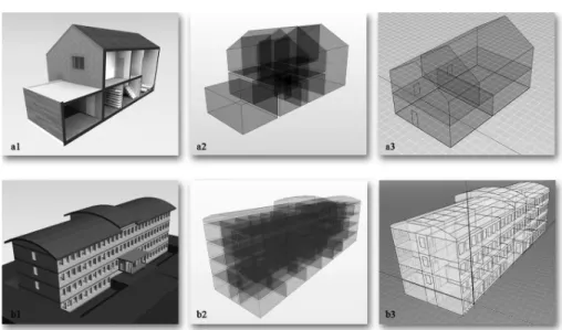
The figure below illustrates our work. It shows a BIM model built in ArchiCAD version 13 (fig. a1 and b1) and exported in IFC. The IFC structure has been validated in the Solibri IFC viewer tool (2012) (fig. a2 and b2). It has then been processed and converted into the PEB format (fig. a3 and b3).
Figure 1. From Archicad to the PEB energy assessment software
This model-driven approach has brought to light a few issues related with some very specific and advanced modeling functions within traditional modeling tools.
The resulting IFC files were different than what the user could see in their CAD software. These problems were not due to the IFC format itself, but to the lack of maturity of the IFC support of the CAD tools.
The BIM software produces a geometrical model that is visually correct. But during the IFC export, some of the geometrical information is wrongly translated, leading to an incorrect IFC model.
To illustrate this, we will detail two examples with two well known architectural software. We will focus on the modeling aspects of the junctions between walls and their upper frontiers.
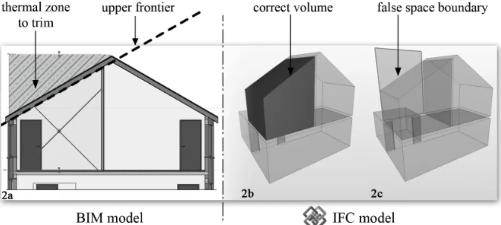
The first example is based on Revit Architecture from (Autodesk). To reach a complete BIM model, one has to define the different structural elements of the building, the envelope and its properties, the openings, the thermal volumes and other miscellaneous information. One problem appeared while defining the thermal zones. Revit offers an efficient tool to do so, but this information gets lost during the IFC export. The software automatically detects the 2D frontiers of a plan, but the user has to manually adjust the height of the volume, in a way to cross the top boundary of the building. The software will automatically computes the intersection of the volume and the top elements and removed any exceeding parts of the newly defined volume. Unfortunately, this correct result gets corrupted during the IFC export. The profiled space boundaries don't make their way into
IFC. Instead, we see the boundaries of the uncut initial volume. When we get a correct visual representation of the thermal zone in Revit (fig. 2a – 2b), its space boundaries in IFC are geometrically incorrect (fig. 2c).
Figure 2. Thermal volume defined in Revit Architecture and its IFC export The second example is based on ArchiCAD from Graphisoft (version 15). It appears with some "dynamic" tools, like "trim/join wall to roof". The specificity of these tools is that it maintains the declared relationship even if you move one of the components afterwards. Here again, the visual result is correct. But the geometry exported in IFC doesn’t match the operation. We loose the joining/trimming result and only get the initial components of the operations.
Without any further checking, you might end up with an IFC document providing you with false information, like surface estimations, etc. The solution here is to avoid using these dynamic tools, and instead use classical boolean subtraction operations. This generates a correct IFC model. However these operations are hardly reversible in case of future modification.
These different examples should not stop you from trying to use IFC in your projects. The encountered problems are due to a lack of maturity in the supporting tools, and this should be improved in the next versions of the software (the new ArchiCAD release already offers an extended support of IFC over the previous version).
Still, we advise you to evaluate the IFC result you get on a "per design tool" basis, before adopting it in your projects. That way, you should be able to know which tool subset in your CAD software is fully IFC compliant, thus preventing you from any bad surprise during your project phase.
3. Developing for IFC
IFC is an extensive data schema, formally described with the STEP representation. Most of the documentation you can find today about the IFC format will be low-level, closely following its STEP notation. The BuildingSmart website (2012) might be the best place to start with. It contains an exhaustive description of all the IFC classes with some helpful information on how to interpret the different fields and relationship. For example, you can find the description of the IfcSpace here1.
Despite this important source of information, it requires a long time to get accustomed to the IFC model. The reasons for this come from two combined and very valid design choices described below.
Firstly, IFC relies a lot on inheritance. For instance, IfcWallStandardCase, the most common wall representation in IFC, is at the bottom of a long inheritance chain of 7 parents. This causes some learning overhead, as other classes might have unexplicit links to IfcWallStandardCase through any of these ancestors.
Secondly, in IFC, relationships are first class objects, which is a powerful way of decoupling the elements and their relationships. It also allows for properties to be stored in the relationship. But this increases the learning curve, as one must browse that many classes in order to understand how some specific elements are bound together.
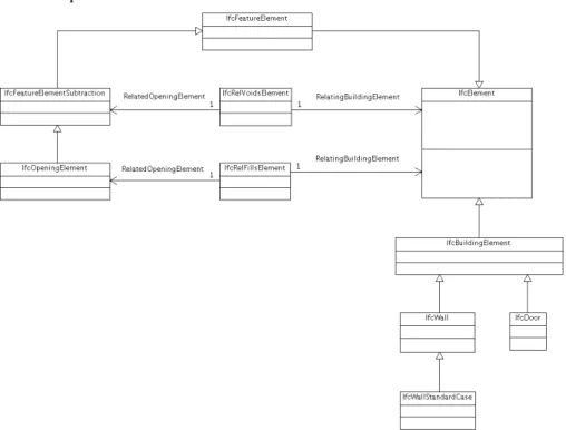
We want to emphase that these design choices are perfectly valid and are sound decisions. They also prove to be useful once one has some experience with the format. Still, as far as the initial learning is concerned, these characteristics makes it very difficult to understand how objects are linked together without further documentation than the low level IFC description. The following example will illustrate this (see Figure 4). It shows the class diagram for the relationships between a Wall and a Door. In IFC, both of these elements inherit from IfcElement. There is no direct relationship between a wall and a door. Instead, an IfcElement can be linked to an IfcFeatureElementSubtraction through an IfcRelVoidsElement. An IfcOpening is of type IfcFeatureElementSubtraction, and can be linked to another IfcElement, like a door, through an IfcRelFillsElement.
After some thoughts, this makes much sense, but documentation is lacking about this, so you have to figure out this schema from reading on all the description of these different classes.
Figure 4: class diagram for the relationships between a wall and a door
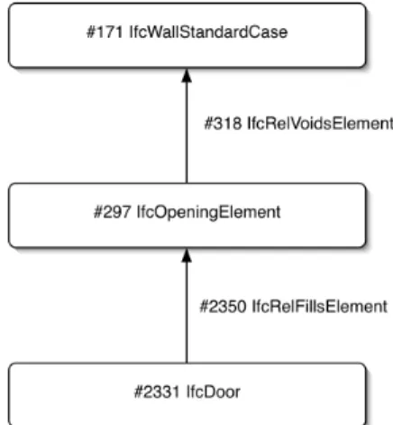
Instead of trying to figure out the IFC format by reading its class descriptions only, we advice you to work with an 'object diagram' approach. The strategy is to model a simple example of the elements and relationships you want to study in an IFC compliant modeling tool, to export its IFC file, and to reverse engineer the given document. Indeed, if you consider only the
‘concrete’ objects, the wall-door relationship will look like the following figure which is far easier to understand:
Figure 5: objects graph for the relationships between a wall and a door
Our developments were made in Java. We have relied on the Open IFC Java Toolbox library (2012), a convenient library to parse and access IFC documents. We have developed a small tool able to display whatever selected element types we are interested in, and all or some of the relationships linking these elements. With this tool, we can see how concrete objects are linked. By focusing only on concrete objects, we bypass the heavy hierarchy of IFC, and by displaying all the relationships, we do not have to study the exact semantic of the IFC relations. Once we have learnt enough "by example" with our object diagrams, you can go back to the classes documentation and easily reconstruct the above class diagram.
This approach has started to be adopted in the IFC world, and you will find more object diagrams in the building smart documentation of IFC 2.4 than in the documentation of version 2.3.
4. Conclusion
IFC is a lot more than the few elements considered in this article. The format addresses products, processes, resources and contexts. In this research, we have focused on some of the core aspects of IFC: a few of the main products and their geometries.
Considering the vast ambition of IFC and the many issues such an interoperable file format might encounter, we didn’t know how good IFC would be to cope with the few challenges considered in our evaluation.
At first, we have suffered from the lack of a high level documentation and from some modeling issues in the commercial offer. When these
critics are nothing fundamental about IFC, they may seriously limit the adoption of the technology by newcomers. We have tried to provide the reader with some useful strategies to work around these few problems, in order to speed up the initial learning phase of IFC. Also, the recent progress in both the norm description and the modeling tools have brought some improvement on these problems.
After some time playing with IFC, we could take advantage of the format and get some real benefits from it. We were able to read IFC from a couple of different modelers and convert it into a dedicated thermal assessment format. So IFC has correctly fulfilled its interoperable mission within this project.
After these first conclusive tests, we have also evaluated the export of IFC files in another project of ours, where a dedicated modeler was being built. In this context, the results were excellent: we were able to export our BIM project into most of the main commercial modeling tools, opening our software with limited analysis capabilities to a whole new range of features available in external applications.
On both the modeling and development side of our study, we have found that IFC was able to cope with today’s challenges, at the cost of an adapted modeling/developing strategy requiring some time for learning and evaluating the technology.
Acknowledgements
This project was funded by the ARGENCO department of the University of Liège. This article has been supported by the SpatioData project funded by the Walloon Region (WIST3 N° 1017094).
References
Ashrae: 2009, An Introduction to Building Information Modeling. American Society of Heating, Refrigerating and Air-conditioning.
Azhar, S., Hein, M. and Sketo, B.: 2008, Building Information Modeling: Benefits, Risks and Challenges, Proceedings of the 44th ASC National Conference, Auburn, Alabama, USA. BuildingSmart: 2012. Available from: http://www.buildingsmart.com/
Coates P., Arayici Y., Koskela L., Kagioglou M., Usher C. and O’ Reilly K.: 2010, The
limitations of BIM in the architectural process, First International Conference on
Sustainable Urbanization (ICSU 2010) Hong Kong, China, 15-17 December 2010. Deutsch R.: 2011, BIM and Integrated Design - strategies for architectural practice, Wiley. Eastman, C., Teicholz, P., Sacks, R. and Liston, K.: 2011, BIM Handbook: A Guide to
Building Information Modeling for Owners, Managers, Designers, Engineers and Contractors, 2nd edition ed. USA: Wiley, 2011.
Liebich T., Adachi Y., Forester J., Hyvarinen J., Karstila K., Reed K., Richter S., Wix J., Industry Foundation Classes IFC2x Edition 3 Technical Corrigendum 1, 2011. Available from http://www.iai-tech.org/ifc/IFC2x3/TC1/html/index.).
Open IFC Java Toolbox, 2012. Available from http://www.openifctools.org/ Open_IFC_Tools/Home.html.
Solibri, 2012. Available from http://www.solibri.com/solibri-model-viewer.html
Verstraeten, R., Jonckheere, T., De Meyer, R. and Van Campenhout, J.: 2011, A nice thing
about standards..., Sustainable Construction & Design, Ghent, Belgium, 16 - 17 Feb.
2011.
Verstraeten R., Pauwels P., DeMeyer R., Meeus W., VanCampenhout J. and Lateur G.: 2008,
IFC-based calculation of the Flemish energy performance standard, In A. Zarli & R.
Scherer (eds.): Proceedings of the 7th European Conference on Product and Process Modelling (ECPPM): eWork and eBusiness in Architecture, Engineering and Construction, Taylor & Francis Group, London, 2008, pp. 437-443.