CFD Modeling of Turbulent Air Flow in Three
Different Diffusers Used For
Turbocharger Compressor
A. Chehhat*, S. Boulahrouz, A. Aboudi, B. Chermime and O. Chahaoui
Department of Mechanical engineering, Faculty of science and technology Abbes Laghrour University of Khenchela
Khenchela, Algeria
*achehhat@gmail.com, Boulahrouz_salim@yahoo.fr,
abboudiabdalaziz@yahoo.fr, cherbrah@yahoo.fr, Oualid.chahaoui@gamail.com Abstract— This study is carried out to investigate by CFD
modeling the three dimensional turbulent air flow through the centrifugal compressor used in turbocharger of diesel engines, the full compressor stage with vaned and vaneless diffusers is considered (i.e. From the impeller inlet to the volute outlet). A great attention has been attributed to the effect of the diffuser solidity. For this purpose, three diffusers have been considered (vaneless diffuser, conventional vaned diffuser, and low solidity vaned diffuser) in order to analyze their effect, especially on the turbulence intensity distribution, on the pressure loss, and on the compressor performance. To validate numerical model, a comparison with a similar tested turbocharger is made in case of vanless diffuser, and a good agreement is seen.
Keywords- Centrifugal Compressor, Turbocharger, Turbulence, Compressible Flow
I. INTRODUCTION
The choice of the turbocharger components to form a complete system with a turbocharged engine is a complex balance of design considerations. The engine speed is variable; the required performance must meet the largest possible operating range. In a competitive market, high performance and better fuel economy will be needed. These criteria must be met with a turbocharger requiring less space and adding minimal weight. The adaptation of the turbocharger to the engine is not a recent problem but the anti-pollution standards more stringent require automakers to further control the engine emissions. To carry out the calculations that are used to adapt the engine turbocharger, it is necessary to have an accurate representation of each turbocharger component and an ability to determine the behavior of the entire system with all its components. In this context and in the last years, numerical simulations and experimental measurements have been put in hand to ensure a good understanding of physical phenomena related to the internal flow through the turbocharger. Many research works on the impeller diffuser interactive phenomenon have been undertaken so far. But it is found from the literature that the study of the diffuser solidity effect on the performance of the turbocharger centrifugal compressor by varying the number of diffuser vanes has not been the focus of attention in these works. The experimental study of Mohtar et al. (2011)
showed that the pinched diffuser and the modification of the volute tongue location affects the compressor efficiency and pressure lines at high speed. Two numerical studies of Jio et al. (2009) have shown that: - the vaneless diffuser and the open angle diffuser give the stable operating range and high efficiency. – The study of the air flow through the turbocharger compressor with dual volute design revealed that the dual volute design could separate the compressor into two regions treated separately with dual diffuser design, this investigation confirmed that the dual volute design improves a stable operating range comparing with single volute design. The impeller-diffuser -interaction in a centrifugal compressor have been studied by Anish et al.(2007), four different types of diffuser configurations were generated, by varying the radial gap between the impeller and diffuser. It is shown that the dependence of the compressor stage efficiency is well correlated to such interaction. Dai et al.
(2008) studied the performance of two different volutes with the same impeller. A good agreement has been obtained between the numerical computation and the experimental measurements in volutes, at least at a moderate mass flow rate. It is well known that the turbulence and flow field studies, may also give a good idea on the pressure variation in the compressor, in this subject, Penarbasi (2009) presented a detailed flow measurements at inlet plane of a centrifugal compressor vaneless diffuser and concluded that four regions of high shear are identified within the flow: within the blade wake, between the passage wake and jet, within the thickened hub boundary layer and between the blade wake secondary flow passage vortex. This study confirmed that each of these regions is associated with high turbulent kinetic energy. Aghaaei et al (2008) proposed a comparison of turbulent methods in CFD analysis of radial turbo machines and introduces the best way to choose turbulence parameters when using FLUENT software, and confirmed that the standard k-ε and RNG k-ε models are superior turbulence methods in CFD analysis of radial turbo machines. It can be observed from most of these numerical studies that the effect of number of diffuser vanes on system performance as well as on the flow field and turbulence in the turbocharger centrifugal compressor. Therefore, in order to analyze the effect of diffuser vanes number on the compressor
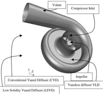
Figure 1: Schematic of the centrifugal compressor stage performance, in this study three types of diffuser are investigated with the same impeller and volute, they only differ in their vanes number; VLD (vaneless diffuser), LSVD (low solidity vaned diffuser), and CVD (conventional vaned diffuser). For this purpose, a commercial CFD software FLUENT is employed considering a steady state method, for simulating the three-dimensional turbulent air flow through the full stage of a centrifugal compressor, used in turbocharger of automobile diesel engine, It is found from the analysis that the diffuser solidity presents a considerable effect not only on the fluid flow and turbulence characteristics, but also on the performances and operating range of the turbocharger compressor.
II. COMPRESSOR GOMETRY MODELLING
The compressor geometry development is carried out in gambit software the various components of the compressor are designed individually and all are assembled. The blade profiles are generated with help of coordinates that have been introduced, a single blade profile is made and then the blades are arranged by further rotating over an angle 360°/z , z is number of blades.
For generating the volume of impeller inside the shroud volume, the blade volume must be subtracted from the shroud volume, a single rotary volume is obtained, and it is limited by the impeller inlet surface, outlet surface, and shroud surfaces, including the blade passage. The diffuser is modeled as a hollow disc; its vanes are modeled as an airfoil located in base angle position. The dimensions of the impeller and the diffuser sketched in figure 1 are shown in table 1.
The volute is modeled by assembling a casing of non-symmetrical cross section beginning from 0° ending at 360°
(when a tongue is located) and a conic pipe discharging in engine admission manifold, see figure 2.
III.MATHEMATICAL MODEL A. Average Navier-Stokes equations
The average Navier-Stokes equations describe the statistic average component of turbulent flows; the instantaneous turbulent field is conventionally decomposed into an average component and fluctuating of zero average [6, 10, 18]. For a steady state compressible flow, these equations are presented in the following conservation form:
• Continuity equation
( )
=0 ∂ ∂ i i u xρ
(1) • Momentum equation(
)
∂ ∂ + − ∂ ∂ + ∂ ∂ ∂ ∂ + ∂ ∂ − ∂ ∂ + ∂ ∂ ∂ ∂ + ∂ ∂ − = ∂ ∂ ij m m t i j j i t j m m ij i j j i j i j i j x u k x u x u x x u x u x u x x P u u xδ
µ
ρ
µ
δ
µ
ρ
3 2 3 2 (2)Where ρ represents the density (kg/m3), u the velocity (m/s), P the pressure (Pa), k the turbulence kinetic energy (m2/s2), µ the laminar viscosity (kg/m s), and µt the turbulent viscosity (kg/ms), the subscripts: i, j and m represent the directions (x, y, and z). δij is the Kronecker delta, it is 1 when i = j, otherwise it is 0. B. Energy equation
[
]
+ ∂ ∂ ∂ ∂ = + ∂ ∂ eff ij i j eff j i i u x T x P E u x ) ( ) (ρ κ τ (3)Where E is the total energy (m2/s2), and the effective thermal conductivity κeff (W/m K) are calculated as:
2 2 u P h E= − + ρ (4)
Description Symbol Dim. (mm)
Number of full blades Z 7
Number of splitter blades zs 7 Impeller outlet diameter/ m D1 0.08 Diffuser outlet diameter /m D2 0.126 Impeller outlet vane height/ m b 0.0045 Inlet shroud diameter /m Ds1 0.068
Inlet hub diameter /m Dh1 0.018
Impeller axial length/ m L 0.026
Inlet mean line blade angle β1 50°
Outlet blade angle β2 30°
TABLE 1
G
EOMETRICAL DIMENSIONS OF THE COMPRESSOR STAGE DESIGNED WITH GAMBITFigure 2: geometry model of turbocharger compressor
Volute
Compressor Inlet
Vaneless diffuser VLD Impeller Conventional Vaned Diffuser (CVD)
∫
= T T P ref dT c h , Tref =288.15K (5) t t p eff c Prµ
κ
κ
= + (6) Where κ is the thermal conductivity of air (W/m K), and cp is the specific heat capacity of air (J/kg K). A constant value of 0.85 is used for the turbulent Prandtl number Prt. The term involves (τij)eff is the viscous stress tensor (kg/m s2) , and (τij)eff (kg/m s2) is defined as:( )
∂ ∂ − ∂ ∂ + ∂ ∂ + = m m ij i j j i t eff ij x u x u x u δ µ µ τ 3 2 ) ( (7)C. Ideal gas Equation
The density variation in case of compressible flow can be determined by the ideal gas equation:
RT P
=
ρ (8)
R is the gas constant (J/kg K) of air, and T is temperature (K);
D. Turbulence modeling
The conservation equations for the turbulent kinetic energy k(m2/s2) and its rate of dissipation ε (m2/s3) are governed by the following equations [6, 10, 18]:
(
)
k M j k t j i i Y G x k x ku x + − − ∂ ∂ + ∂ ∂ = ∂ ∂ ρε σµ µ ρ (9)(
)
k C G k C x x u x k j t j i i 2 2 1 ε ρε ε σ µ µ ρε ε ε ε − + ∂ ∂ + ∂ ∂ = ∂ ∂ (10)Where σk and σε are the turbulent Prandtl numbers for k
and ε, and constant values of 1.0 and 1.3 are used, respectively. Gk (kg/m s3) represents the generation of turbulence kinetic energy due to the mean velocity gradients, and YM (kg/m s3) is the contribution of the fluctuating dilatation in compressible turbulence to the overall dissipation rate, they are calculated as
xi u x u k u u x u G ij j m m t i j j i t K ∂ ∂ ∂ ∂ + − ∂ ∂ + ∂ ∂ = µ ρ µ δ 3 2 (11) RT k YM γ ρε 2 = , and v P c c = γ (12) M
Y is the contribution of the fluctuating dilatation to the dissipation rate (kg/m s3), γ is the specific heat ratio and, µt is calculated as:
ε ρ
µt = Cµk2 (13) Where σk and σε are the turbulent Prandtl numbers for k
and ε, and constant values of 1.0 and 1.3 are used,
respectively. The values of the model constants C1ε, C2ε and Cµ are 1.44, 1.92 and 0.09, respectively.
IV. NUMERICAL SIMULATION A. Grid generation
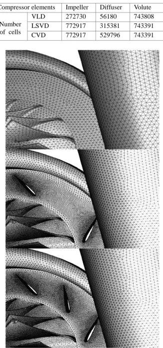
Given the complexity of the compressor geometry, the full computational domain is meshed with tetrahedral grid cells, the clearance gap between the impeller blades and the shroud wall is taken in consideration when meshing the impeller volume, near the impeller blade and diffuser vane walls, the mesh is refined as shown in Figure 3.
The number of mesh cells of each compressor element at different diffusers is shown in table 2.
Compressor elements Impeller Diffuser Volute
Number of cells
VLD 272730 56180 743808
LSVD 772917 315381 743391
CVD 772917 529796 743391
Table 2. NUMBER OF MESH CELLS OF EACH COMPRESSOR ELEMENTS WITH DIFFERENT
DIFFUSERS
Figure 3: Computational wall mesh of the centrifugal compressor full sage with vaned and vanless diffuser
B. Solution settings
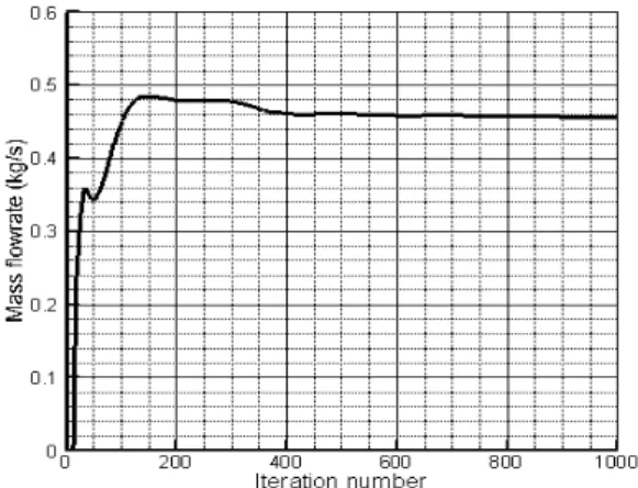
The high complexity of fluid flow in the rotating impeller makes the CFD modeling very difficult, only steady state flow is investigated, the governing equations implemented in a commercial CFD code Fluent 6.3.26 are solved using the finite volume method, with the most appropriate discretization scheme (pressure based implicit solver), the fluid (air) is treated as an ideal gas, the momentum and energy equations are solved using first order scheme, the turbulent kinetic energy and dissipation rate equations are solved using the power low differencing scheme (PLDS), the coupling velocity-pressure correction is treated with SIMPLE (Semi-Implicit Pressure Linked Equation) algorithm. The under relaxation factor for the pressure is taken 0.2 it seems very conservative, a common value of 0.5 is taken for the momentum, energy, and turbulence k-ε model equations. The convergence criteria of 10-4 are used for all the governing equations [24, 25]. The maximum number of iterations is estimated so that the mass flow rate computed for the outlet cross section become unchanged; this can be observed since about 400 iterations for each case of simulation figure 4.
C. Boundary conditions
The meshed fluid volume has only one flow inlet (the compressor inlet) and one flow outlet (the volute exit). For the flow inlet, the pressure inlet boundary condition with atmospheric pressure (101325 Pa) is taken as the total pressure for the compressor entry, the total temperature is taken as the ambient (288.15K), the default values of inlet turbulent kinetic energy and its dissipation rate are taken respectively 1,21 m2/s2 and 1,82 m2/s3. At the volute exit, the pressure outlet boundary condition is used, putting a prescribed static pressure (this value is required by the engine operating conditions, it must be upper than the atmospheric pressure), the actual total temperature at the outlet is calculated or prescribed by the numerical simulation. At both the inlet and outlet, the default values of turbulent intensity and viscosity ratio (10 percent) are taken for the back-flow condition, which corresponds to the occurrence of reversed flow at same grid cell faces of the outlet cross-section. Since all the operating range no apparent reverse flow has been observed when the simulation is converged. For the rotor, all reference frame moving walls are part of the rotating reference frame, These walls are treated as moving walls with rotational speed of zero, relative to the adjacent cell zone which rotating. No rotating
walls in the inertia frame of reference, that are part of the rotating reference frame, are treated as moving walls with a rotational speed of absolute zero [18].
V. VALIDATION
The pressure ratio characteristics from both the CFD calculations and the experiments are shown on the Fig. 5. It can be seen that difference between CFD and experimental results is less than 5%, and this little gap may be explained by the fact that the CFD model does not include all compressor elements with the exact same dimensions, some part dimensions of tested compressor are not available in open literature. That is why calculated mass flow rates with the CFD model at given outlet pressures are not the same as the real compressor. Noting that, this comparison is made for a vanless diffuser compressor which considered as a reference case.
VI. RESULTS AND DISCUSSION
The turbulent air flow through the turbocharger is studied, considering the full stage of the centrifugal compressor, consisting of an air inlet, leading to an impeller that discharges the air radially through a vaned diffuser in the volute. The aim of this study is to predict the influence of varying diffuser vanes number on the flow local characteristics: velocity, pressure and temperature, for this, we consider three types of diffuser with the same impeller and volute, they only differ in their vanes number; VD (vaneless diffuser), LSVD (low solidity vaned diffuser), and CVD (conventional vaned diffuser). All the simulations are carried out for the same rotational speed of 80 000 rpm, and one point of the operating range is chosen for representing pressure and velocity distributions at a flow rate of 0.47 kg/s. A. Static pressure distribution
Fig. 6 show that the static pressure increases rapidly as it exits the impeller and passes through the stator vanes and then slowly increases in the volute. At higher flow rates, the static pressure trend is significantly different from that for low flow rate due to the pressure loss particularly at impeller exit and diffuser inlet. The static pressure recovery in the diffuser vanes and volute occurs at shorter distance in the low number of vane diffuser while it takes longer distance inside the vanes and volute for larger number of vanes diffuser. The peak of the static pressure recovery always occurs after exiting the diffuser inside the volute.
Figure 4: Monitoring of the mass flow rate computed over the compressor outlet during the iteration process
Figure 5: Comparison of pressure ratio characteristic with J90S-2 [8]
The high velocity of air at the diffuser exit for larger number of vanes may lead to longer vane wakes and therefore the flow has to travel longer distance to pass the vortex region and have the pressure recovered. After reaching the peak static pressure, the airflow mixing from all vanes became dominant and therefore a pressure loss occurs in this region. Further away from the mixing region the flow became more uniform and the volute diversion have more influence and therefore the static pressure increases while the total pressure is almost constant [3].
Strong pressure drop and recovery is seen for VLD comparing with the LSVD and CVD diffusers.
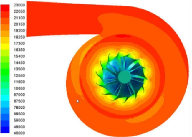
The static pressure distributions at the mid-span of the compressor with different impeller are shown in Figs. 7,8 and 9 it can be observed clearly that for different diffusers, static pressure is gradually increase from impeller inlet to outlet, at the same impeller radius, the static pressure on pressure side is evidently greater than that on suction side. For all diffusers, the uniformity of static pressure distributions in diffuser region is affected by the non-symmetric scroll casing, and this is seen in Fig. 9, when we can remark that the uniformity is better in impeller region for the same rotation speed and same mass flow rate, this is seen as well as the number of diffuser vanes increases [20]
B. Mean velocity distribution
Figs (10a),(10b), and (10c) show the velocity vectors mapped on turbulent intensity distribution, jet-weak phenomenon is clearly seen in impeller exit and diffuser blade passages for LSVD and CVD, while for VLD, jet-weak phenomenon become jet-weaken and recirculation zone in mid-plane is seen only near volute tongue. Fig. (10d) shows the average radial velocity magnitude, it seen that the effect of diffuser solidity is clear in the diffuser region as a deceleration and acceleration zone [3].
Because all the simulations presented in this paper are at the design speed of 80 000 rpm, the tangential velocities at the impeller exit are similar for all the simulations, and the radial velocity at the impeller exit is mainly dictated by the air flow rate. Showing vector plots of velocity, colored according to its magnitude. The recirculation zones on the impeller and diffuser suction sides are clearly visible for all the configurations. The influence of rotating stall comes into force for diffuser vanes with larger number of vanes. The reasons for this are two folds: Firstly the stalling phenomenon is associated with the blade passing frequency.
With larger number of vanes on the diffuser, the blade passing frequency increases leading to rotating stall. Secondly, this occurrence is due to narrower vane passages of the diffuser in which recirculation on the suction side of the diffuser vanes gets converted into a rotating stall [1].
Figure 6. Average of radial pressure over the compressor full stage
Figure 8: Contours of radial static pressure for CVD
Figure 9: Contours of radial static pressure for VLD
VII.CONCLUSION
The numerical modelling and simulation of a chosen compressor with altering Vaneless Diffuser (VD), Low Solidity Vaned Diffuser (LSVD) and Conventional Vaned Diffuser (CVD) was successfully carried out. Analysis of flow from the inlet to the exit of a centrifugal compressor stage is done for different Mass flow rates calculated at a given outlet pressures. The vector plots, turbulent intensity contour plots and Static pressure plots are generated for better understanding of fluid flow through the vanned and vanless centrifugal compressor stage. The results obtained from CFD analysis were validated with the experimental results for the pressure ratio such as a performance parameter and a good agreement is seen with a difference less than 5%, this difference may be explained by the fact that the CFD model does not include all compressor elements with the exact same dimensions, any part’s dimensions of tested compressor are not available in open literature. That is why calculated mass flow rates with the CFD model at given outlet pressures are not the same as the real compressor. To obtain a close agreement, the calculated mass flow rate must be corrected.
ACKNOWLEDGMENT
The authors would wish to thank Pr. Georges Descombes from CNAM de Paris and Dr. Haitham Mezher from Ecole Central de Nantes (France) for their useful suggestions and worthy discussions about this work.
REFERENCES
[1] Ali Pinarbasi, Turbulence measurement in the inlet plane of a centrifugal compressor vaneless diffuser, Ijhff, 30, (2009), 266-275 [2] Chehhat A., Si-Ameur M., Boumeddane B. (2018) Turbulent Air
Flow Investigation Through the Vaned Diffuser Turbocharger Using CFD. In: Aloui F., Dincer I. (eds) Exergy for A Better Environment and Improved Sustainability 1. Green Energy and Technology. Springer, Cham
[3] Abdelmadjid Chehhat, Mohamed Si-Ameur, Essam Abo-Serie, Salim
Boulahrouz, Numerical investigation of diffuser solidity effect on turbulent airflow and performance of the turbocharger compressor, Applied and Computational Mechanics. 2016, vol. 10, no. 2, p. 79-96.
[4] Chehhat Abdelmadjid, Si-Ameur Mohamed and Boumeddane
Boussad, CFD Analysis of the Volute Geometry Effect on the Turbulent Air Flow through the Turbocharger Compressor, Energy Procedia 36, (2013), 746-755
[5] Cheng Xu, Michael Muller, Development and design of a centrifugal
compressor volute, International Journal of rotating machinery 3, (2005),190-196
[6] Cumpsty, N. A. (1999), Compressor Aerodynamics, Longman
Scientific, University of Cambridge
[7] H. Mohtar, P. Chesse, D. Chalet, J.-F. Hetet and A.Yammine, Effect
of Diffuser and Volute on Turbocharger Centrifugal Compressor Stability and Performance: Experimental Study, Oil & Gas Science and Technology – Rev. IFP Energies nouvelles, 66(5), (2011),779-790
[8] J90S-2 turbocharger. Manufactured by Weifang Xinde Make Industry
and Trade Co., Ltd, Shandong, China. http://wxmiatcl.en.china.cn [9] J. Galindo, J. R. Serrano, H. Climent, A. Tiseira, Experiments and
modelling of surge in small centrifugal compressor for automotive engines, etfs,32, (2008), 818-826
[10] [1] K. Jiao, H Sun, X Li, H Wu, E Krivitzky, T Schram, and L M Larosiliere, Numerical investigation of the influence of variable
Figure 9: Velocity vectors mapped on turbulent intensity contours and average radial of velocity magnitude for different
diffusers
(a) (b)
(c)
diffuser angle on the performance of a centrifugal compressor, Proc IMechE Part D: J. Automobile Engineering 223, (2009),1061-1070
[11] [2] K. Vasudeva Karanth , N. Yagnesh Sharma, Numerical analysis
on the effect of varying number of diffuser vanes on impeller - diffuser flow interaction in a centrifugal fan, World Journal of Modelling and Simulation , 5, (2009),63-71
[12] Koji Nakagawa, Hiroshi Hayami and Yuichi, Comparison of Two Diffusers in a Transonic Centrifugal Compressor, International Journal of Rotating Machinery, 9, (2003), 279–284
[13] Kui Jiao, Harold Sun, Xianguo Li, Hao Wu, Eric Krivitzky, Tim Schram, Louis M. Larosiliere, Numerical Simulation of air flow through turbocharger compressors with dual volute design, Applied Energy, 86, (2009), 2494-2506
[14] Mahdi Nili-Ahmadabadi, Ali Hajilouy-Benisi, Mohammad Durali,
Farhad Ghadak, Investigation of a Centrifugal Compressor and Study of the Area Ratio and Tip Clearance Effects on Performance, Journal of Thermal Science .17(4), (2008), 314−323
[15] N Bulot, J Trébinjac, X Ottavy, P Kulisa, G Halter, B Paolitti, and P Krikorian, Experimental and numerical investigation of flow field in a high-pressure centrifugal compressor impeller near surge, Proc IMechE 223 Part A: J. Automobile Engineering (2009), 657- 666 [16] Ozturk Tatar, Adnan Ozturk and Ali Pinarbasi JSIR, Flow analysis in
centrifugal compressor vaneless diffusers, 6, (2008),348-354
[17] Q Guo, H Chen, X-C Zhu, Z-H Du, and Y Zhao, Numerical
simulations of stall inside a centrifugal compressor, Proc IMechE Vol.221 Part A: J. Automobile Engineering (2007), 683- 693
[18] R. Aghaei tog, A. M. Toussi, A. Tourani, Comparison of turbulence methods in CFD analysis of compressible flows in radial turbo machines, An Aircraft Engineering and Aerospace Technology: an International journal 80(6), (2008), 657-665
[19] Reza Aghaei tog, A. Mesgharpoor Toussi, M. Soltani, Design and CFD analysis of centrifugal compressor for a microgasturbine, An Aircraft Engineering and Aerospace Technology: an International journal 80(06), (2008), 137-143
[20] S Anish and N Sitaram, Computational investigation of impeller-diffuser interaction in a centrifugal compressor with different types of diffusers, Proc IMechE Vol.223 Part A: J. Automobile Engineering (2008), 167- 178
[21] Syed Noman Danish, Shafiq Rehman Qureshi, Abdelrahman
EL-Leathy, Salah Ud-Din Khan, Usama Umer, Ma Chaochen, Numerical Investigation & Comparison of a Tandem-Bladed Turbocharger Centrifugal Compressor Stage with Conventional Design, J. Therm. Sci., 23(6), (2014), 523-534
[22] S. Yahia , (2005), Turbines Compressors and Fan, 2nd edn. Tata Mc
Graw Hill
[23] Y. Dai, A. Engeda, M Cave, and J-L Di Liberti, Numerical study and experimental validation of the performance of two different volutes with the same compressor impeller, Proc IMechE Vol.223 Part A: J. Automobile Engineering, (2008),157- 166
[24] Fluent 6.3 user’s guide, 2006 (Fluent Inc., Lebanon, New Hampshire)
[25] GAMBIT 2.2 user’s guide, 2004 (Fluent Inc., Lebanon, New