HAL Id: hal-01897568
https://hal-imt-atlantique.archives-ouvertes.fr/hal-01897568
Submitted on 17 Oct 2018
HAL is a multi-disciplinary open access
archive for the deposit and dissemination of
sci-entific research documents, whether they are
pub-lished or not. The documents may come from
teaching and research institutions in France or
abroad, or from public or private research centers.
L’archive ouverte pluridisciplinaire HAL, est
destinée au dépôt et à la diffusion de documents
scientifiques de niveau recherche, publiés ou non,
émanant des établissements d’enseignement et de
recherche français ou étrangers, des laboratoires
publics ou privés.
Performance of Mobile Relays in Loaded Conditions for
Railway Transportation
Mauricio Iturralde, Thomas Galezowski, Xavier Lagrange
To cite this version:
Mauricio Iturralde, Thomas Galezowski, Xavier Lagrange. Performance of Mobile Relays in Loaded
Conditions for Railway Transportation. ITST 2018 : 16th International Conference on Intelligent
Transport Systems Telecommunications, Oct 2018, Lisbon, Portugal. �10.1109/ITST.2018.8566864�.
�hal-01897568�
Performance of Mobile Relays in Loaded
Conditions for Railway Transportation
Mauricio Iturralde
IMT Atlantique, IRISA
mauricio.iturralde@imt-atlantique.fr
Thomas Galezowski
Soci´et´e du Grand Paris
thomas.galezowski@societedugrandparis.fr
Xavier Lagrange
IMT Atlantique, IRISA
xavier.lagrange@imt-atlantique.fr
Abstract—Deploying mobile relays in public transportation is a simple yet effective way to avoid the electromagnetic insulation within vehicles and to increase the Quality of Service (QoS) perceived by passengers, which is sometimes low. Mobile relaying can be done by using an LTE/EPC 100%-compatible architecture. However, this solution induces extra-overhead. In this paper we evaluate the QoS of an LTE mobile relay architecture for public railway transport systems for two representative services: client-server requests and voice communications. We compare the performance of a direct transmission against a mobile relay architecture for different types of requests and different load conditions. This work, therefore, evaluates the mobile relay performance in terms of load time, throughput, packet loss ratio and end-to-end latency. Our findings show that a mobile relay architecture highly improves the QoS performance for train passengers. Furthermore, the gain is greater as the load increases.
Index Terms—QoS, LTE, 4G, mobile relay
I. INTRODUCTION
The use of wireless broadband services is rising significantly with the deployment of Long Term Evolution (LTE) networks and the generalisation of smart phones, tablet computers and other new mobile devices. People make intensive use of these devices when they are on public transport vehicles such as buses, trams, or trains. It is anticipated that, by the year 2020, it will be fairly common to have up to 50 active vehicular User Equipments (UEs) per bus and up to 300 active vehicular UEs per train [1].
The service quality in public transport is far from satisfac-tory. Vehicles are usually well shielded with coated windows, which leads to a rather high penetration loss between outdoor and in-vehicle. The penetration loss can be as high as 25 dB, and even goes up to 35 dB in the Shanghai high-speed magnetic levitation train [2]. Traditionally, the UEs inside the public transport system are connected to macro base stations via wireless links, in which the penetration loss severely attenuates the signal quality and decreases the achievable data rate. Deploying mobile relays with both an outdoor antenna to communicate with the cellular network and an indoor antenna to provide a good coverage to passengers is a natural solution to provide a high QoS.
Soci´et´e du Grand Paris is in charge of designing and constructing the new 200km of fully automated metro lines around Paris, connecting the 3 Paris airports as well as the main suburban and innovation areas. These ”Grand Paris
Express” lines, interconnected with the existing Paris subway, regional trains and bus lines, will carry around 2 Million passengers per day. Soci´et´e du Grand Paris is seeking to provide continuous high quality telecommunication services to passengers in Grand Paris Express stations and inside trains. Thus, Soci´et´e du Grand Paris is interested in developing new technologies such as mobile relays in order to serve this purpose.
In [3] we showed with a testbed using real radio trans-missions that a mobile relay architecture can be easily imple-mented with standard Evolved Packet Core (EPC) and with full compatibility with 3GPP recommendations. However, since this solution induces extra overhead and extra latency, the QoS of this solution needs to be evaluated.
The objective of this paper is to evaluate the performance of the mobile relay architecture where a train is loaded with several users using HyperText Transfer Protocol (HTTP) and Voice over Internet Protocol (VoIP) services.
The remainder of this paper is organised as follows. In Section II we present the state-of-the-art of mobile relay in LTE. In Section III we describe the architecture and the protocol stack when mobile relays are used. In Section IV we analyse the advantages and limits of mobile relays. In Section V we describe our simulation scenario within the traffic models and we also present our QoS parameters. In Section VI we present and analyse our findings and finally Section VII concludes our document.
II. RELATEDWORKS
Previous works have focussed on the architectural aspect of Mobile Relay [4] [5] [6], data-rate gain and QoS aspects. In [4] the authors outline and sum up the main network architecture aspects for mobile relay handling. They analyse two types of mobile relay architecture. This paper takes into account the handover aspects as well. In [5], the architecture for mobile relay is presented. The key techniques of supporting mobile relay are investigated, such as the group mobility, the local service support, the multi Radio Access Technology (RAT) and Radio Access Network (RAN) sharing, with the corresponding solutions. In [6] authors propose to keep the same protocol stack as for fixed relays but introduce the concept of a global tunnel, which gathers several tunnels for the mobile relay architecture. This architecture is compatible with the GPRS Tunneling Protocol (GTP). The authors show that without
adding any protocol in the stack, it is possible to group several handovers while keeping the possibility of managing the tunnel of each UE individually.
Other works have pointed their attention to the data rate gain aspect [7], [8], [9], [10] and [11]. The authors analyse in [7] the data rate gain provided by a mobile relay deployed in public transportation systems. Also an analysis of the penetration loss factor between outdoor and in-vehicle is presented. They found that the loss factor has an important influence on the data rate gain when using a relay architecture. In [11] the authors analyse the data rate gain when using mobile relays in public transportation. The loss factor and the on-board user’s throughput gain when avoiding it is also studied. They found that avoiding the train loss factor, the on-board users receive a 30% higher bit rate. In [8], authors studied the performance of dual-hop transmission with a mobile relay and with a fixed relay by means of a theoretical analysis and simulations and proved the benefit of mobile relays when the penetration loss is above 25 dB. In [9], stochastic analysis is used to compute the capacity of a cell when mobile relays are used. In [10] joint transmission by both a mobile relay and a macro-cell base station is proposed to improve the data rate of non-vehicular UEs and the outage probability is derived.
The QoS aspect is studied in [12]. Authors studied the mobile relay capacity improvement for on-board train users and its impact on the overall network performance. This paper analyses the gain in terms of throughput when transmitting video streaming for only 10 on-board train users.
Some other studies consider mobility protocol issues. In [13], several architectures based on the 3GPP analysis [14] are described. In [15], [16], the authors optimized the handover for mobile relays deployed on high speed trains by using the predictability of movement on a railway. In [17], the authors discussed several architecture alternatives for mobile relays and proposed intra mobility area mobile relay handover and inter mobility area mobile relay handover procedures. The handover latency of these procedures are analysed. However, this proposal requires extra planning effort on the operator side and some upgrades of the standard 3GPP based protocols.
The Third Generation Partnership Project (3GPP) investi-gated several possible architectures for mobile relays in [14]. Some solutions require the modification of several protocols and thus an important standardisation effort. However, the first alternative (called alt1) described in [14] is based on the fact that nodes of the EPC such as Mobile eNB (eNBm), Mobile Management Entity (MME) just need Internet Protocol (IP) connectivity and that IP connectivity can be simply provided by an LTE/EPC network. In [3] we proved this concept with real radio transmissions.
To our knowledge, there has been as yet no systematic examination of interactive and VoIP services in mobile relays. The question remains, however, how those services perform under a mobile relay architecture in loaded conditions.
PDN GW MMEg
SGWg Uu
S1-U (between eNBm and SGWg)
S5/S8
S1-MME S11
S6a
SGi HSSg
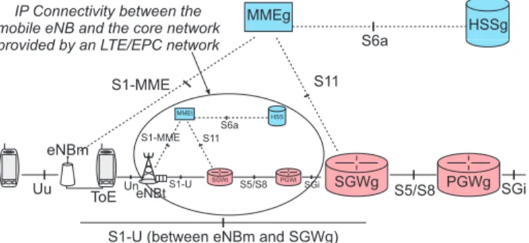
IP Connectivity between the mobile eNB and the core network provided by an LTE/EPC network
PDN GW MMEt SGWt PGWt Un S1-U S5/S8 S1-MME S11 S6a SGi eNBt HSS ToE eNBm PGWg
Fig. 1: Architecture of a network with a mobile relay
III. MOBILERELAYMECHANISM
An LTE/EPC mainly includes the following nodes: the Evolved Node B (eNB), the MME, Serving Gateway (SGW), Packet Gateway (PGW), and the Home Subscriber Server (HSS).
The wireless access for passengers is provided by the use of two nested LTE/EPC networks as shown in Figure 1. The first one is called the Track Evolved Packet Core (EPCt) and acts as a backhaul network. Nodes of this network are identified by suffix t (eNBt, MMEt, SGWt, etc.). We name a terminal of this network a Transport Operator terminal Equipment (TOE). There is typically one TOE in every train. The second network is the general network. It manages the UEs of passengers and could be owned by operators. It has eNBm as well as standard eNB. Note that eNBms have access to the general network through the track network: an eNBm is connected to a TOE and can thus exchange messages with Global Mobile Management Entity (MMEg) and Global Serving Gateway (SGWg).
It is worth mentioning that all these elements are standard LTE components, and that the use of this architecture requires no adaptation of protocol stacks or hardware.
There can be several general networks that use the same LTE/EPC track network in order to allow all mobile operators of a country to provide the service on-board. There can be several eNBms (one per operator) but Radio Access Network (RAN) sharing can also be used to avoid a duplication of embedded hardware in trains. Note that Figure 1 shows a functional architecture. The operator of the track network can be a mobile operator and several entities can be physically in the same node (e.g. MMEt and MMEg are in the same piece of equipment)
The protocol stack when a mobile relay is used is shown in Figure 2 on the radio interface and on the S1-interface. Due to the use of two LTE/EPC networks there is an additional level of encapsulation and thus extra-headers compared to a standard architecture. The following headers are added to each packet: 8-12 bytes for GTP [18], 8 bytes for the User Datagram Protocol (UDP) and 20 bytes for the Internet Protocol (IP) (with IPv4). The GTP header length is 12 only when packet numbering is activated in GTP. We consider the worst case and thus assume a 12-byte header, which gives a 40-byte total
overhead. As the length of the internal packets is variable, an important question is to determine whether this 40-byte overhead is negligible or not compared to the user data average size for popular services such as telephony and HTTP.
Fig. 2: Protocol header in a mobile relay
IV. IMPACT OF RELAYING ON TWO SERVICES
In this section, we analyse the possible benefits brought by the deployment of mobile relays. We consider two represen-tative services, namely client-server requests and telephony.
A. Interactive services
We consider a generic interactive service as shown in figure 3 with a request-response protocol. The UE sends a request to a server. The server then transfers a file, which can be a web page, a video or a text. The application protocol is HTTP and the transport protocol is the Transmission Control Protocol (TCP).
Fig. 3: HTTP client-server model
The main QoS indicator is the loading time defined as the total time to transfer the whole file from the time the request was sent. To get a better insight into the procedure, we break
down the loading time into the server response time and the file reception time (see figure 3).
Due to the additional transmission on the backhaul com-pared to a direct configuration, there is one more radio hop with a mobile relay. The server response time is thus increased. According to [19], a website’s size can be from 150 KB up to 8 MB. Thus IP packets are set to their maximum length, which is generally 1500 bytes. The 40-byte extra overhead is thus negligible. The file reception time can be dramatically reduced thanks to a much better radio link budget.
B. Telephony service
In 4G networks, telephony is based on VoIP. End users are generally sensitive to the packet loss rate and the one-way delay. ITU-T G.114 [20] recommends a maximum of 150 ms one-way latency in order to avoid any problems due to possible echoes and to keep excellent interactivity between the two parties. Since this includes the entire voice path, part of which may be on the public Internet, the LTE/EPC network should have a transit latency less than 150 ms. As for the interactive service, using a relay increases the one-way delay.
The relative cost of the extra-overhead on the backhaul can be not negligible. Though there are several possible modes for the speech codec, the most representative one is the GSM Enhanced Full Rate (EFR) codec: A 244-bit data block is sent every 20 ms, which gives a rate of 12.2 kbps. There is generally a cyclic redundancy check (CRC) that is added. The payload is thus 32 bytes. The sizes of the header added by the VoIP protocol stack are12 bytes, 8 bytes and 20 bytes for RTP, UDP and IPv4, respectively. We assume that the PDPC, RLC and MAC layers add headers whose total length is 6 bytes [21]. In standard VoIP over LTE, the required bitrate on the radio interface is(6 + 40 + 32) × 8/20 = 31.2 kbps. With the relay extra overhead (see figure 4), the required bitrate on the backhaul is (6 + 40 + 40 + 32) × 8/20 = 47.2 kbps. The increase is 47.2/31.2, that is +51%. The question is to know whether the throughput increase really compensates the additional overhead.
Fig. 4: VoIP packet
V. CONFIGURATION OF THE SIMULATION
This section presents the performance achieved by multiple UEs while loading web pages and performing conversational voice calls. The objective of these simulation experiments is to analyse the performance of the mobile relay architecture when servicing multiple HTTP and VoIP requests.
A. Simulation Environment
For performing our tests we used network simulator version 3 (ns-3) [21]. This is a discrete-event network simulator for Internet systems that has a well developed LTE Module for
600 meters 600 meters 100 kmph
Fig. 5: Mobility Scenario
research and educational use. The ns-3 LTE module has two main components: the LTE model and the EPC model.
The LTE Model includes the LTE Radio Protocol stack (RRC, PDCP, RLC, MAC, PHY) and the EPC Model includes core network interfaces, protocols and entities. These entities and protocols reside within the SGW, PGW and MME nodes, and partially within the eNB nodes. We use the standard NS3 LTE model with direct transmission between UEs in the train and the network as the reference mode.
The LTE module has been modified to implement the mobile relay architecture scenario (see Figure 1). In particular, the en-capsulation and deen-capsulation mechanisms are fully simulated. We tested the performance of the mobile relay architecture and we compared them against a direct transmission scenario.
In our scenario, a train moves in a linear way with a velocity of100 kmph as shown in Figure 5. Base stations (eNBt) are regularly deployed along the track and have a 600-m radius. The intersite distance is thus 1200 m. Handover is perfect both for the direct and the relay modes (no packet loss and no call drop). The eNbt and the eNbm transmit on different frequencies. Therefore, the inter-cell interference is avoided.
Two train loads are considered : 20 and 100 mobile users. We assume 60% of the passengers make HTTP requests and the remaining 40% have VoIP communications. The simulation parameters are presented in detail in Table I.
B. HTTP Traffic Model
We considered different mean sizes for the file : 20 000, 100 000 and 500 000 bytes. Inspired by [19], we assume the size follows a Weilbull r.v., whose CDF is
FX(x) = 1 − e−(x/λ)
k
. (1)
where k > 0 is the shape parameter and λ > 0 is the scale parameter of the distribution. The value of k used is 0.8. The value of λ is fixed in order to get the chosen mean size for files. For mean sizes of 20 000, 100 000 and 500 000 bytes the values ofλ are 17 652, 88 261 and 441 305, respectively. After each file transfer, the user reads the content. The reading time is modelled by an exponential r.v. with a mean value of 39.7 seconds. At the end of reading time, a new request is sent to the server by the terminal.
C. VoIP Traffic Model
We simulate VoIP communications with an Enhanced Full Rate (EFR) codec or equivalently an AMR-WB codec in 12.65-kpbs mode (see [22]). The source traffic generates a 32-bit data block every 20-ms. There is no voice activity de-tection. Hence, the flow is constant bit rate. The RTP/UDP/IP headers are added to each data block.
Parameters Value
System Type FDD
Temperature 290K
Simulation Time 100s
Train penetration loss 15dB For TOE and eNbt (Backhaul link) Propagation Loss Model Kun2600 MHz
Number of TOEs 1
eNbt Cell’s radius 600m
eNbt Tx Power 27dBm
TOE Tx Power 23dBm
TOE Noise Figure 7dB
eNbt Noise Figure 3dB
Bandwidth for eNbt 20MHz
Downlink Frequency for eNbt 2620 .0MHz Uplink Frequency for eNbt 2500
.0MHz Mac Scheduler Proportional Fairness For UEm and eNbm (Access link) Propagation Loss Model Friis Model
Number of UEm 20 up to 100
Number of eNbm 1
eNbm Cell’s radius 100m
UEm movement speed 100 kmph
eNbm Tx Power 27dBm
UEm Tx Power 23dBm
UEm Noise Figure 7dB
eNbt Noise Figure 3dB
Bandwidth for eNbm 20MHz
Downlink Frequency for eNbm 2655 .0MHz Uplink Frequency for eNbm 2535
.0MHz Mac Scheduler Proportional Fairness
TABLE I: Simulation Parameters
We assume the calls are set up prior to the simulation and did not consider any call arrival and call release. No signalling is simulated.
D. QoS Parameters
For the HTTP flows we define the following parameters:
Server Response Time: This indicator is computed for each requestu as
ηu = tfp,u− trq,u (2)
where, tfp,u is the time stamp of the first received packet by
the UE andtrq,u is the time stamp of the request sent by the
UE to the server (see figure 3).
Page Reception Time: This indicator is computed as ξu= tlp,u− tfp,u (3)
where tlp,u is the time stamp of the last packet received by
the UE.
Page Load Time: The page load time is simply the sum of the server response time and the page reception time:
Throughput: This parameter measures the throughput obtained when receiving the HTTP file. This parameter is calculated as: α = 1 U U X u=1 Bu tlp,u− tfp,u (5)
whereU is the total number of requests during the simulation, Bu is the amount of bytes received after requestu.
And for the VoIP flows we analyse the latency and the Packet Loss Ratio (PLR).
Packet Loss Ratio: This parameter measures the end-to-end packet losses. This parameter is calculated as:
ρ = 1 U U X u=1 Ptx,u− Prx,u Ptx,u (6)
wherePtx,uis the number of transmitted packet by the server,
Prx,u is the number of received packets at the UE.
VI. RESULTS AND ANALYSIS
In this section we first analyse the QoS performance of HTTP client-server file transfer by regarding several parame-ters such as: file load time, server response time, and through-put. Secondly we look at the VoIP performance based on QoS parameters such as: PLR and end-to-end latency.
Our figures represent the statistical distribution of values by using box plots with the upper quartile, median and lower quartile. The whiskers represent the maximum and minimum values excluding outliers. Outliers are the points which fall more than 1.5 times the interquartile range above the third quartile or below the first quartile.
A. Results of HTTP flows
Figure 6 depicts the effect of the mobile relay in terms of page load time when the train is loaded by 60 users downloading HTTP files (within a total of 100 users). For 500-kB files, the median load time is reduced from7 s to 2.5 s and is thus divided by 3. The maximum load time is reduced by30 s. Users are generally very sensitive to such a reduction of the load time. Even for moderate-size file for which the load time is by nature small, it is reduced by the use of a relay. In all cases, the maximum load time is always smaller in the relay mode (1 s vs 2 s for 20-kB files, 4 s vs 15 s for 100-kB files,22.5 vs 52 s for 500-kB files).
The average sever response time is increased by about 20 ms when a relay is used as shown in figure 7. This is due to the supplementary radio hop. However, the response time can be larger than 80-ms (and even sometimes larger than 120 ms) in the direct mode due to bad radio conditions as opposed to the relay-mode where the maximum value is about 75 ms. This means that using a relay is beneficial even for client-server applications in which a very small amount of data is downloaded.
Figure 8 shows the throughput when downloading an HTTP file. When the train is close to the base station, radio condi-tions are excellent and the rate is high. Thus, the maximum throughput in the direct mode is close to the one in the relay
0 5 10 15 20 25 30 35 40 45 50 55 20k 20k 100k 100k 500k 500k Load Time [s] Bytes direct relay
Fig. 6: Boxplot of http load time for different file sizes
20 40 60 80 100 120 140 160 20k 20k 100k 100k 500k 500k
Server Response Time [ms]
Bytes direct
relay
Fig. 7: Boxplot of http server response time
mode (e.g.1.2 Mbps vs 1.3 Mbps for 100-kB files). However, the minimum throughput is lower in direct mode at about0.1 Mbps in comparison to relay mode at0.25 Mbps. Even without specific QoS policy, the mobile relay helps to offer a minimum bit rate (of course except in highly saturated conditions with a huge number of passengers). The average throughput is much larger with the relay mode. The throughput gain increases as the file size is larger. Due to the slow-start mechanism, the TCP protocol takes greater advantage of the best channel conditions reached by the relay architecture when the file is larger.
Figure 9 shows the effect of the mobile relay in terms of page load time when the train is loaded by 12, 60 and 120 users downloading HTTP files of 100-kB. For 12 users the median load time is less than 1 s for both the direct and the relay modes. For such low load, the relay does not provide any benefit but does not degrade the QoS.
The maximum load time is reduced by the use of a relay from 16 s to 4 s for 60 users and from 39 s to 13 s for 120
0 0.2 0.4 0.6 0.8 1 1.2 1.4 20k 20k 100k 100k 500k 500k Throughput [Mbps] Bytes direct relay
Fig. 8: Boxplot of throughput for http flows
users. The median is divided by2 and the maximum load time is divided by3 for 120 users. For moderate to high loads, there is a clear interest to use mobile relays. Note that a train loaded by 120 users in relay mode shows a shorter load time than a train loaded by 60 users in direct mode. This means that the use of a mobile relay allows serving about twice the number of users with a slightly higher QoS.
0 5 10 15 20 25 30 35 40 12 12 60 60 120 120 Load Time [s] http users direct relay
Fig. 9: Boxplot of http load time for different loads
B. Results of VoIP flows
Figure 10 shows the distribution of the latency. Since in the relay architecture packets have more hops, it increases the latency from about 25 ms to 25-37 ms. As the latency is less than 40 ms, this guarantees a good voice calling interaction since the latency threshold is 150 ms. Furthermore, a simple Proportional-Fairness scheduler is used. It does not give any priority to VoIP packets. By using a dedicated bearer for VoIP packets on the backhaul, it is possible to give a higher priority to voice packets and to limit the latency increase.
24 26 28 30 32 34 36 38 40 42 44 20k 20k 100k 100k 500k 500k Latency [ms] Bytes direct relay
Fig. 10: Boxplot of VoIP latency
The PLR for VoIP flows was measured for each simulation. It is not shown in this paper because only very few packets were lost and using boxplots for displaying results has no statistical significance. For both direct and relay modes, the loss is less than0.01%. This confirms that the radio conditions of the direct mode are not so bad and our comparison for all services is fair: the configuration parameters we chose represents a reference case (i.e. the direct mode) with a good quality coverage scenario. In such conditions, the gain for interactive services is clearly visible. It can be larger if the coverage inside the train is poor in the direct mode.
VII. CONCLUSIONS
This study has focused attention on the analysis of the QoS performance of mobile relays in a standard LTE architecture for a railway scenario. We evaluated the QoS of HTTP and VoIP services when a train is loaded up to two hundred users simultaneously using the LTE Network.
Implementing a mobile relay solution in trains highly im-proves the quality of interactive services and keeps an excellent quality for VoIP services.
It is clear from the current study that avoiding penetration losses improves the QoS for the passengers, even if the mobile relay architecture generates an additional overhead of40 bytes to each transmitted packet. The gain for interactive services is more important for long downloaded files and for high load conditions.
Since the QoS in a relay architecture depends of the behavior of both the mobile eNb and the eNBs covering the track, future works should focus on scheduling techniques for real-time and non-real time services. Also the performance of handovers should be studied.
REFERENCES
[1] Popovski et al. Scenarios, requirements and kpis for 5g mobile and wireless systems. The METIS project: Mobile and wireless
communi-cations Enablers for the Twenty-twenty Information Society, Tech. Rep. ICT-317669-METIS D, 1, 2013.
[2] Liu Liu et al. Position-based modeling for wireless channel on high-speed railway under a viaduct at 2.35 ghz. IEEE Journal on Selected
Areas in Communications, 30(4):834–845, 2012.
[3] Tanguy Kerdoncuff, Thomas Galezowski, and Xavier Lagrange. Mobile relay for lte: proof of concept and performance measurements. In
Vehic-ular Technology Conference (VTC Spring), 2018 IEEE 87th (accepted paper). IEEE, 2018.
[4] Andrey Krendzel. Lte-a mobile relay handling: Architecture aspects. In
European Wireless Conference (EW), IEEE 19th, pages 1–6, 2013. [5] L. Chen et al. Mobile relay in lte-advanced systems. IEEE
Communi-cations Magazine, 51(11):144–151, November 2013.
[6] Y. Chen and X. Lagrange. Analysis and improvement of mobility procedures for mobile relays in lte networks. In 2015 IEEE 26th
Annual International Symposium on Personal, Indoor, and Mobile Radio Communications (PIMRC), pages 1769–1774, Aug 2015.
[7] Yangyang Chen and X. Lagrange. Downlink data rate gain provided by a mobile relay for lte-advanced. In 2013 16th International Symposium
on Wireless Personal Multimedia Communications (WPMC), pages 1–5, June 2013.
[8] Yutao Sui, Agisilaos Papadogiannis, and Tommy Svensson. The poten-tial of moving relays-a performance analysis. In Vehicular Technology
Conference (VTC Spring), 2012 IEEE 75th, pages 1–5. IEEE, 2012. [9] Y. Chen, F. Yan, and X. Lagrange. Performance analysis of cellular
networks with mobile relays under different modes. Telecommunication
systems, 66(2):217–231, Oct 2017.
[10] Xiaoxuan Tang et al. Coverage performance of joint transmission for moving relay enabled cellular networks in dense urban scenarios. IEEE
Access, 5:13001–13009, 2017.
[11] Y. Chen and X. Lagrange. Downlink capacity gain analysis of mobile relay in lte-advanced network. In 2014 IEEE 11th Consumer
Communi-cations and Networking Conference (CCNC), pages 544–550, Jan 2014. [12] J. Calle-Sanchez et al. Theoretical analysis and performance simulation of in-band lte mobile relays in railway environments. In 2014 28th
International Conference on Advanced Information Networking and Applications Workshops, pages 725–730, May 2014.
[13] Lin Chen et al. Mobile relay in lte-advanced systems. IEEE
Communi-cations Magazine, 51(11):144–151, November 2013.
[14] 3rd Generation Partnership Project. Evolved Universal Terrestrial Radio Access (E-UTRA); Study on mobile relay (Release 12). V12.0.0 Technical Report 36.836, 3GPP, June 2014.
[15] Meng-Shiuan Pan, Tzu-Ming Lin, and Wen-Tsuen Chen. An enhanced handover scheme for mobile relays in lte-a high-speed rail networks.
IEEE Transactions on Vehicular Technology, PP(99):1, 2014. [16] Qing Huang et al. Mobile relay based fast handover scheme in
high-speed mobile environment. In IEEE Vehicular Technology Conference
(VTC Fall), pages 1–6, September 2012.
[17] Christian Pietsch et al. Moving Relays and Mobility aspects. Technical report, Artist4G deliverable, May 2012.
[18] 3rd Generation Partnership Project. General packet radio system (gprs); tunnelling protocol user plane (gtpv1-u) (release 8). V8.5.0 Technical Specification 29.281, 3GPP, March 2010.
[19] R. Pries et al. An http web traffic model based on the top one million visited web pages. In Euro-NF Conference in Next Generation Internet
(NGI), 2012 IEEE 8th, pages 133–139. IEEE, 2012.
[20] ITU-T Recommendation G.114. One-way transmission time. Technical report, Artist4G deliverable, 2003.
[21] ns-3 simulator. Available at: http://www.nsnam.org/.
[22] 3rd Generation Partnership Project. Universal mobile telecommunica-tions system (umts); lte; codec for enhanced voice services (evs); (release 14). V14.2.0 Technical Specification 26.445, 3GPP, Jan 2018.