UNIVERSITÉ DE MONTRÉAL
BIOMECHANICAL MODELING OF VERTEBRAL MECHANOBIOLOGICAL
GROWTH AND OF THE DEFORMATION PROCESS IN ADOLESCENT
IDIOPATHIC SCOLIOSIS
HUI LIN
DÉPARTEMENT DE GÉNIE MÉCANIQUE ÉCOLE POLYTECHNIQUE DE MONTRÉAL
THÈSE PRÉSENTÉE EN VUE DE L’OBTENTION DU DIPLÔME DE PHILOSOPHIAE DOCTOR (Ph.D.)
(GÉNIE MÉCANIQUE) JUIN 2010
UNIVERSITÉ DE MONTRÉAL
ÉCOLE POLYTECHNIQUE DE MONTRÉAL
Cette thèse intitulée:
BIOMECHANICAL MODELING OF VERTEBRAL MECHANOBIOLOGICAL GROWTH AND OF THE DEFORMATION PROCESS IN ADOLESCENT IDIOPATHIC SCOLIOSIS
présentée par: LIN Hui
en vue de l'obtention du diplôme de: Philosophiae Doctor a été dûment acceptée par le jury d'examen constitué de:
M. YAHIA L’Hocine, Ph.D., président
M. AUBIN Carl-Éric, Ph.D., membre et directeur de recherche
Mme. VILLEMURE Isabelle, Ph.D., membre et codirectrice de recherche M. PARENT Stefan, MD. Ph.D., membre et codirecteur de recherche M. PETIT Yvan, Ph.D., membre
ACKNOWLEDGEMENTS
I am profoundly grateful to my supervisor, Professor Carl-Éric Aubin for his excellent direction and innovative researching ideas as well as financial support. I also thank my co-supervisors, Dr. Isabelle Villemure and Dr. Stefan Parent, for their valuable supervision on project building, paper writing and clinical knowledge application. Their intelligent research methods and professional dedication for my doctoral work will be of great benefit to my future career pursuit.
I gratefully acknowledge those at Sainte Justine and Polytechnique who provided significant technical supports for my project. I appreciate Hicham Gharbi and Alexi Popov for their help on model developing and French translation. I thank Philippe Labelle for his helpful work on patient image reconstruction. Julie Joncas helped with the acquisition of clinical data and Christian Bellefleur gave aid on patient image processing. The assistance on the finite element modeling given by Julien Clin is also appreciated. Nathelie Jourdain provided valuable help on my training for MENTOR program. I appreciate Mylène Lajoie for her help on the permission of copy right.
I would like to express my gratitude to my current and previous lab mates, Mark Driscoll, Christopher Driscoll, Eric Wagnac, Simon Desgreniers, Younes Majdouline, Archana Sangole, Wang Xiao-yu, Nadine-Michele Lalonde, Fanny Canet, and other colleagues in Sainte Justine and Polytechnique. They help me warm-heartedly whenever I have difficulties on work and French.
I am grateful to Xu Xin who gave me significant support in life during my doctoral work. She always encouraged me to overcome difficulties whenever I was in hardship. The mental support she provided inspired me with innovative ideas in my research. I also thank my parents and my brother and sister for their encouragement through the doctoral study.
RÉSUMÉ
La scoliose idiopathique chez l’adolescent est une déformation tridimensionnelle du rachis se développant durant la croissance. Plusieurs études rapportent que la progression de la déformation scoliotique est influencée par des facteurs biomécaniques. La déformation scoliotique, l’asymétrie de la balance du rachis et l’activité musculaire sont responsables du chargement asymétrique sur les plaques de croissances. Ces facteurs modifient la répartition entre le côté concave-convexe du taux de croissance et, par conséquent, conduit à un cercle vicieux de progression de la déformation scoliotique. Le processus biomécanique de la progression de la scoliose a été étudié dans la littérature en considérant principalement une composante de chargement axiale pour la représentation de la croissance.
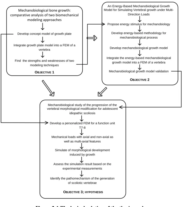
L’objectif général de ce projet est d’étudier la biomécanique multiaxiale de la progression scoliotique. Le but spécifique du projet est de vérifier que le processus de déformation, impliquant la croissance et sa modulation mécanobiologique par des charges multi-axiales, est stimulable numériquement par la méthode des éléments finis, et que ces charges multi-axiales exercées sur les plaques de croissance épiphysaires sont responsables des déformations caractéristiques des vertèbres et rachis scoliotiques. Le chargement utilisé pour simuler la pathologie consiste en des forces primaires axiales asymétriques combinées à des forces secondaires de cisaillement et de torsion. Afin d’atteindre ce but, le projet a été divisé en trois parties. La première partie a consisté à faire une étude comparative de deux techniques de modélisation afin de simuler les concepts de croissance mécanobiologique. La seconde partie a consisté à développer un nouveau modèle de croissance mécanobiologique, basé sur l’énergie de stimulation, afin de représenter les déformations vertébrales résultant du chargement multiaxial. La troisième partie a consisté à soumettre le nouveau modèle numérique à différents cas de chargements et à analyser leurs influences sur la croissance et sur la progression de la scoliose.
Dans la première partie, les formulations analytiques de la croissance mécanobiologique développées par Stokes et coll. (1990) et Carter et coll. (1988) ont été comparées entre elles à l’aide d’un modèle par éléments finis d’une vertèbre thoracique. La vertèbre et la plaque de croissance adjacente supérieure ont été modélisées par des éléments solides 3D linéaires. Le
modèle de Stokes tient compte seulement du chargement axial, tandis que le modèle de Carter inclut des charges multiaxiales. Les plaques de croissances épiphysaires ont été représentées par trois couches distinctes : une couche sensible aux chargements, une couche de croissance et une couche minéralisée. Les modèles mécanobiologiques de croissance de Stokes et coll. (1990) et Carter et coll. (1998) ont été numériquement intégrés au modèle de la plaque de croissance. Différentes conditions de chargements physiologiques ont été appliquées sur la vertèbre (tension, compression, cisaillement, tension/cisaillement et compression/cisaillement) afin d’étudier la modulation de croissance. Une procédure progressive incrémentale discrète a été utilisée afin de représenter la croissance longitudinale géométrique de la vertèbre. Les résultats de simulations du modèle de Stokes et coll. (1990) ont été comparés aux résultats de simulation du modèle de Carter et coll. (1998) et des différences significatives ont été observées entre les deux modèles. Le modèle de Carter a présenté une faible capacité à retarder la croissance sous l’effet des forces de compression et les forces de cisaillement contribuent significativement à stimuler la croissance. Par contre, le modèle de Stokes retarde significativement la croissance sous l’effet de forces de compression et les forces de cisaillement n’ont pas d’effet sur la croissance. Le ratio des taux de modulation de croissance entre les modèles de Carter et Stokes est supérieur à 10 lorsque le modèle par élément finis est soumis à une combinaison de forces de compression et de cisaillement. Les résultats de simulation ont indiqué que les modèles de Stokes et Carter sont incapables de simuler complètement la croissance selon des conditions de chargement multiaxial. Afin de pouvoir correctement simuler les conditions de croissance selon les chargements multiaxiaux, un nouveau modèle de croissance, basé sur l’énergie, a été développé. L’énergie est un stimulus transportant la réponse biomécanique responsable de la croissance. Le processus de modélisation de croissance a été représenté par des formulations analytiques et a été divisé en deux composantes : la composante mécano-sensible basée sur le sondage d’énergie ainsi que la composante de mécano-régulation basée sur l’énergie. La composante mécano-sensible est responsable de la transformation du chargement mécanique en réponse biologique à l’aide de l’énergie. La composante de mécano-régulation suit la composante mécano-sensible et induit les modifications biologiques. Le modèle de croissance mécano-biologique basé sur l’énergie a été développé selon ces deux composantes et a été implanté numériquement au modèle par éléments finis de la plaque de croissance développé dans la première partie du projet décrite
précédemment. Ce nouveau modèle de croissance intégré au modèle par éléments finis a été testé selon différents cas de chargement (tension, compression, cisaillement, tension/cisaillement et compression/cisaillement) et l’évaluation a été faite par comparaison avec des études expérimentales et numériques publiées dans la littérature. Les résultats de simulation pour les cas de chargements axiaux sont en accord avec le principe de Hueter-Volkmann, le modèle de Stokes et les expérimentations faites sur les animaux. Les contraintes de cisaillement augmentent la croissance mécano-biologique de 20 à 40% dans les cas de chargements axiaux/cisaillement, ce qui est en accord avec les résultats de Carter.
Le nouveau modèle de croissance développé permet de représenter les chargements multiaxiaux et les modifications de la morphologie vertébrale des adolescents atteints de scoliose idiopathique. Le processus de modification morphologique a été simulé avec un modèle par éléments finis. Le nouveau modèle de croissance a été intégré dans un modèle numérique pédiatrique d’un segment fonctionnel T7-T8 personnalisé à un patient mâle non pathologique âgé de 11 ans. Des cas de chargement axiaux, de cisaillement, de torsion et des effets combinés axial/cisaillement et axial/torsion ont été simulés. Les mesures prises sur les modèles numériques incluent les angles d’inclinaisons des plateaux de T7 (cunéiformisation), qui sont des mesures essentielles de la déformation vertébrale chez les patients scoliotiques, et la rotation axiale entre T7et T8. Les résultats de simulations ont indiqué que les chargements axiaux et non axiaux modifient l’inclinaison des plateaux vertébraux dans le plan coronal (1.4o
~4.8o) et la rotation intervertébrale (0.7o~3.7o). L’angle d’inclinaison des plateaux dans le plan sagittal n’est pas beaucoup affecté (0.1o~1.0o). Le chargement asymétrique axial induit une modification de l’inclinaison des plateaux vertébraux du modèle numérique de 4.8o
, ce qui se rapproche des résultats publiés dans la littérature (5.2o) de Parent et coll. (2003).
L’étude comparative de la première partie du projet a déterminé les forces et limites des modèles de croissance de Stokes et Carter. En effet, le modèle de Stokes est en accord avec des études expérimentales et s’ajuste correctement dans le cas des chargements axiaux. Cependant, le modèle de Stokes n’est pas capable de représenter la croissance selon des chargements multiaxiaux, ce qui limite son application afin de prendre en compte les environnements mécaniques complexes du rachis tels que ceux observés chez les patients
scoliotiques. Le modèle de Carter tient compte des effets mécano-biologiques des charges multiaxiales et dérive théoriquement des modèles de formation de l’os. Toutefois, ce dernier modèle ne tient pas compte de l’orientation de croissance résultant des stimuli de contraintes de chargement 3D. Le nouveau modèle de croissance développé dans ce projet utilise le concept de stimulus énergétique, intégrant physiquement des contraintes mécaniques multiaxiales. Les résultats de simulations pour le nouveau modèle de croissance développé est en accord avec la plupart des études expérimentales et les études théoriques et mécano-biologiques de Carter. Ce projet confirme l’implication des charges axiales et non axiales dans le développement de la scoliose. Aussi, cette étude conclut que l’inclinaison des plateaux vertébraux chez les patients scoliotiques est présente uniquement dans le plan coronal. Cette étude confirme le rôle primaire du chargement axial et le couplage secondaire des efforts de cisaillement et de torsion dans le développement de la scoliose. Le concept d’énergie peut également expliquer les mécanismes de couplage existants dans les charges multiaxiales. Les charges multiaxiales induisent des composantes de contraintes axiales et non axiales, ce qui est physiquement intégré de manière non linéaire dans le modèle énergétique. Cette non linéarité mène au couplage mécano-biologique généré par les charges multiaxiales.
Cette étude propose une approche biomécanique permettant de trouver des risques de progression de la déformation scoliotique du rachis. Cette étude permet également le design et l’optimisation d’un schéma de correction pour la scoliose à partir de résultats de simulation. La méthodologie innovatrice de la croissance mécanobiologique développée dans le modèle par éléments finis offre une aide pertinente dans la compréhension biomécanique de la scoliose et dans le design de traitements minimalement invasifs.
ABSTRACT
Adolescent idiopathic scoliosis is a three dimensional deformity of spine that mostly occurs during the growth spurt. It is generally accepted that the progression of scoliotic deformities is influenced by biomechanical factors. Asymmetrical loading of vertebral growth plates resulting from an initial scoliotic curve or asymmetric balance or muscle recruitment are modifying the concave-convex side growth rate, thus leading to a vicious circle of scoliosis progression. The mechanobiological process of scoliosis was previously investigated, but mainly considering the axial loading component for growth.
The general objective of this project was to study the multi-axial biomechanics of scoliosis progression. The specific objective was to model the deformation process, including the spinal growth and mechanobiological growth modulation due to multi-axial loads, and analyze how these loads are involved in the resulting characteristic scoliotic deformities. This tested pathomechanism presents the primary loading characteristics of asymmetric axial forces combined with secondary shear and torsion. In order to address the proposed research objectives, this project was divided into three parts. The first one was a comparative study and analysis of two modeling techniques to simulate existing concepts of mechanobiological growth. The second part was the development of a novel model of mechanobiological growth based on energy stimulus that enabled to represent the vertebral changes due to multi-axial loading. In the last part, this model was exploited to simulate the effect of different loads and analyze how they influence the growth process and how they relate to the scoliotic pathomechanism.
In the first part, the analytical formulation of mechanobiological growth developed by Stokes et al. (1990) and Carter et al. (1988) was compared using a finite element model representing a thoracic vertebra as solid elements. Stokes’s model only concerned axial stress, while Carter’s model involved multi-axial stresses. The epiphyseal growth plates were represented using three layers similar to those found in the vertebral bodies: a loading sensitive area, a growth area, and a mineralized area. The two mechanobiological growth models were numerically integrated into the growth plate model. The two models were further used to simulate vertebral growth modulation resulting from different physiological loading conditions applied on
the vertebra (tension, compression, shear, as well as combined tension/shear and combined compression/shear). The growth simulation used a stepwise incremental procedure to represent the longitudinal growing geometry of the vertebra. Significantly different growth patterns were triggered in both models by the loading cases. Carter’s model presented a weak capability of retarding the growth under compression forces but shear forces had a more important contribution in stimulating growth. In contrast, Stokes’s model significantly retarded the growth under compression but shear forces had no effect. The combined compression/shear further highlighted the differences with much over ten times of the ratio of growth modulation rates between the two models. Simulation results indicated that neither models were fully able to simulate growth under multi-axial loading conditions.
In order overcoming the limitations of the two tested mechanobiological models, an innovative model was proposed. The energy was proposed as a stimulus for carrying out the mechanobiological response. The modeling process was divided into two components and represented as analytical formulations: energy-triggered mechanosensing and energy-based mechanoregulation. Mechanosensing carried out the transformation of mechanical loading into biological response by energy. Mechanoregulation followed the mechanosensing and induced the biological modification. The energy-based mechanobiological growth model was finally developed from those two analytical procedures. It was implemented in the growth plates of the previously developed vertebra finite element model. The model was tested with different loading conditions (tension, compression, shear, combined tension/shear, and combined compression/shear), and the validation was based on comparisons with published experimental studies on growth response to axial and shear loading in animals, and numerical simulation of growth modulation in humans. Simulation results under axial loading conditions agreed with the Hueter-Volkmann law, the Stokes’ model and animal experiments. The shear stress increased the mechanobiological growth (20%-40%) in the combined axial /shear loading condition, which agreed with the Carter’s mechanobiological theory.
The energy-based growth model involved multi-axial stresses and made it possible to reproduce the modification of vertebral morphology similarly as what is seen in adolescent idiopathic scoliosis. The morphological modification process was simulated by using finite
element modeling technique. Energy-based model was integrated into a pediatric FEM model of a thoracic functional unit T7-T8 personalized to an eleven-year-old healthy male child. The spinal loads were designed as axial loading, shear, torsion, and combined axial/shear or torsion. The measurement included the wedging angle of T7, which was an essential characteristic to measure a vertebral deformity, and intervetebral axial rotation between T7 and T8. Simulation results indicated that both axial and non-axial loading (shear) were able to induce the wedging of the vertebrae in the coronal plane (1.4o~4.8o) and the intervertebral rotation (0.7o~3.7o). The wedging angle in the sagittal plane was little modified (0.1o~1.0o). The asymmetric axial loading induced a 4.8o wedging angle that approached published measurements (5.2°) of Parent et al (2003).
The comparative study found the strengths and limits of two modeling techniques. The Stokes’s model was supported by experimental studies and recognized in the axial loading conditions. However, the exclusion of non-axial stresses would limit its application on a complex mechanical environment of spine such as those seen in scoliosis. Carter’s model considered the mechanobiological effects of multi-axial stresses and was theoretically derived from model of bone formation. Carter’s model did not intrinsically incorporate growth orientation resulting from the 3D stress stimuli. Energy stimulus physically involved multi-axial stresses in terms of mechanics. The innovative model using energy stimulus thus naturally integrated multi-axial stresses. The simulation study indicated that this model agreed with most experimental studies and Carter’s theoretical studies in mechanobiology. This study confirmed the mechanobiological contribution of both axial and non-axial loading to the development of scoliotic vertebrae. This study found that scoliotic wedging occurs only in the coronal plane. This study confirmed the primary role of axial loading on inducing scoliotic vertebrae and coupling secondary role of shear and torsion. The energy concept can also explain coupling mechanisms existing in multi-axial loads. Multi-axial loads resulted in axial and non-axial stresses, which non-linearly physically integrated into energy. This non-linearity led to coupling mechanobiological impact generated from those loads.
This study provides a biomechanical approach to find potential risk of spine deformation progression in adolescent idiopathic scoliosis. Designing and optimizing a correction scheme for scoliosis also benefit from this study by means of biomechanical simulation to find the potential
outcome of a correction. The innovative methodology on mechanobiological growth developed with the finite element model offers a biomechanical assistance for the understanding of scoliosis biomechanics and the design of minimal invasive treatments.
CONDENSÉ EN FRANÇAIS
La scoliose idiopathique des adolescents (AIS) est une déformation tridimensionnelle de la colonne vertébrale qui se développe durant la poussée de croissance. Les causes de progression de cette pathologie sont inconnues. On croit que les facteurs mécaniques jouent un rôle important dans la déformation scoliotique. Le chargement mécanique a été rapporté comme une stimulation épi-génétique, modifiant la croissance, la modélisation et le remodelage osseux changeant la morphologie de l’os, son histologie et ses propriétés mécaniques, comme observé dans la scoliose.
La réponse biologique des tissus squelettiques aux stimuli mécaniques (mécanobiologie) se traduit par la modification du développement du squelette. La loi de Wolff et le principe de Hueter-Volkmann sont considérés respectivement comme des concepts de base du remodelage osseux et de la modulation de croissance. Fondamentalement, le processus mécanobiologique comprend : le mécano-sondage, la mécano-transduction et la mécano-régulation. Ces procédures conduisent à la transformation des stimuli physiques en réactions biochimiques ainsi qu’en réponses biologiques finales. Les réponses existent au niveau de la croissance, la modélisation et le remodelage osseux.
Deux modèles d'analyse de la croissance mécano-biologique ont été développés selon deux méthodes différentes: le modèle de Stokes et le modèle de Carter. Le modèle de Carter décrit initialement un modèle d’ossification d'un os long et associe la contrainte de compression hydrostatique et la contrainte de cisaillement octahédrale avec l'ossification du cartilage. La théorie de Carter a été appliquée au niveau de l’incorporation de la croissance et de l'ossification endochondrale, permettant ainsi le développement d’un modèle de croissance mécanobiologique. Ce nouveau modèle fut plus tard intégré dans les modèles d'éléments finis (FEM) du fémur proximal et distal pour prédire la dysplasie développementale de la hanche et l'angle bicondylien du fémur résultant de la croissance longitudinale du fémur. Le modèle de croissance de modulation de Stokes était initialement issu de la relation hypothétique linéaire entre le taux de croissance et de la contrainte axiale. Ce modèle a été créé pour les côtes et pour simuler la déformation thoracique liée à scoliose. Des travaux expérimentaux complémentaires supportent
le modèle de Stokes et permettent l’évaluation des paramètres du modèle. Ce modèle a ensuite été appliqué au modèle biomécanique de la colonne vertébrale pour étudier l’effet de la croissance sur le développement de la scoliose. Le modèle a été intégré dans un modèle par éléments finis de la colonne vertébrale pour simuler la croissance du corps vertébral et pour trouver les mécanismes mécano-biologiques de la scoliose. En outre, le modèle de croissance des jonctions neurocentrales utilise ce modèle pour l’étude du rôle des jonctions dans le développement de l’AIS.
À ce jour, seul le modèle de Stokes est appliqué à l'étude biomécanique de la scoliose. Toutefois, seulement une contrainte axiale est impliquée dans ce modèle. Puisque la colonne vertébrale, saine ou pathologique, est soumise à des charges dynamiques complexes (multi-axiales), le modèle de Stoke comporte plusieurs limites. En outre, il n'existe aucune étude sur des techniques de modélisation afin d'identifier leur rationalité physiologiques. Les effets mécanobiologiques sur le chargement multiaxial de la croissance vertébrale favorisant le développement de vertèbres scoliotiques devrait être étudiés. Les vertèbres et structures intervertébrales complexes affichent des caractéristiques géométriques pouvant entraîner des environnements mécaniques complexes.
Par conséquent, le processus de croissance mécanobiologique et ses impacts sur le développement des vertèbres scoliotiques seraient pertinents dans l’évaluation des pathomécanisme de la AIS. L'objectif général de ce projet est d'étudier les impacts mécanobiologiques de charges multiaxiales sur le développement des vertèbres scoliotiques. Le but spécifique du projet est de vérifier que le processus de déformation, impliquant la croissance et sa modulation mécanobiologique par des charges multi-axiales, est simulable numériquement par la méthode des éléments finis, et que ces charges multi-axiales exercées sur les plaques de croissance épiphysaires sont responsables des déformations caractéristiques des vertèbres et rachis scoliotiques.
Les objectifs suivants ont été proposés dans cette thèse:
Objectif 1 Faire une étude comparative des techniques de modélisation existantes. Cet objectif inclut les sous-objectifs suivants:
Objectif 1.1 Élaborer un modèle conceptuel d'une plaque de croissance et créer un modèle par éléments finis.
Objectif 1.2 Évaluer les modèles actuels de croissance mécanobiologique.
Objectif 2 Développer un modèle de croissance physiologique mécanobiologique des vertèbres.
Objectif 2.1 Élaborer un modèle de croissance plus physiologique et mécanobiologique que les modèles existants.
Objectif 2.2 Simuler la croissance longitudinale vertébrale par l'intégration avec le modèle de croissance développé.
Objectif 2.3 Évaluer le nouveau modèle de croissance mécanobiologique.
Objectif 3 Identifier les pathomécanismes possibles du développement des vertèbres scoliotiques par simulation de la croissance:
Objectif 3.1 Exploiter le modèle mis au point pour analyser les effets de chargement axial et non axial sur le développement morphologique des vertèbres.
Objectif 3.2 Identifier l'effet de couplage mécanobiologique des charges multiaxiales sur la génération des vertèbres scoliotiques.
Pour le premier objectif, les modèles de Stokes et de Carter ont été analysés et comparés en utilisant une approche par éléments finis d'une vertèbre. Les modèles intégraient un modèle conceptuel de la plaque de croissance. Ce modèle a été utilisé pour simuler la modulation de croissance vertébrale résultant de différentes conditions de chargements physiologiques appliquées sur la vertèbre (tension, compression, cisaillement, tension/cisaillement et compression/cisaillement).
Cette étude a permis de développer un modèle permettant de simuler la croissance et sa modulation mécanobiologique. Ce modèle est basé sur l'énergie provenant de forces multi-axiales appliquées sur les plaques de
croissance. Ces procédures ont permis la mise au point d’un modèle de croissance mécano-biologique. Le modèle a été testé sur le modèle par élément finis d'une vertèbre. Les tests étaient basés sur les aspects suivants: les études théoriques de Carter sur la mécanobiologie, les études expérimentales sous un chargement axial et de cisaillement et la comparaison avec le modèle de simulation numérique de Stokes à des conditions de chargement axial. Les conditions de chargement testées comprenaient le chargement axial, le chargement non-axial et les cas de chargement combiné, et ont été utilisés par les études publiées. Ces conditions de chargement étaient physiquement présentées comme: tension, compression, forces de cisaillement, forces de tension-cisaillement et forces de compression-cisaillement.
Le modèle de croissance fondé sur l'énergie a été utilisé pour étudier le développement mécano-biologique lié à des vertèbres scoliotiques. Ce modèle a été intégré dans un modèle par éléments finis d'une unité fonctionnelle thoracique T7-T8 qui a été personnalisée sur un enfant de onze ans de sexe masculin en bonne santé. L'évaluation d'une vertèbre scoliotique a été basée sur des mesures de la géométrie vertébrale. Les mesures comprenaient l'angle d’inclinaison de T7 (cunéiformisation) et la rotation axiale intervertébrale entre T7 et T8. Le chargement axial, le cisaillement, la torsion et les chargements axiaux combinés au cisaillement et à la torsion ont été rapportés dans les études expérimentales et ont été utilisés pour simuler l'évolution des morphologies vertébrales.
Dans la simulation pour l'étude de comparaison, des taux de croissance différents ont été déclenchés par la compression et par du chargement combiné tension-cisaillement. Les ratios des taux de modulation de la croissance (Carter/Stokes) étaient de 0,6 et 1,5 respectivement pour ces cas. Des résultats significativement différents entre les modèles ont été trouvés pour les cas de chargement de cisaillement et de cisaillement-compression : le rapport entre les taux de modulation pour le modèle de Carter et le modèle de Stoke était supérieur à 10.
Pour le modèle basé sur l'énergie, des conditions de chargement similaires à celles appliquées sur le modèle de Stokes ont été appliquées. Un taux de croissance mécano-biologique négligeable (51µm) a été mesuré sous les charges de cisaillement pures. L'expérience de Moreland a affiché des résultats similaires (1980). La contribution positive mécano-biologique du
cisaillement, responsable de l’augmentation du taux de modulation de croissance de 20%-40%, a été trouvé dans le cas du chargement combiné.
Les simulations sur le modèle d'unité fonctionnelle T7-T8 montre que le chargement axial induit une inclinaison de 4.80° du plateau de la vertèbre T7, ce qui concorde avec les mesures de Parent (2003). En outre, une rotation intervertébrale de 3,40° a également été produite. Des charges de cisaillement ont également déclenché des changements d’inclinaison de T7 de 2.50°-3.00° dans le plan frontal et des rotations de 1.70°-1.90°. Les charges multiaxiales ont induites des inclinaisons vertébrales de 2.30°-4.40° et des rotations vertébrales de 1,90°-3,10°. Des inclinaisons vertébrales de 0.10°-1.00° dans le plan sagittal ont été également produites.
Les résultats de simulation pour l'étude de comparaison ont montré que le modèle de Stokes était supporté par les études expérimentales sur les conditions de chargement axial. Le modèle de Stokes a été reconnu comme une représentation rationnelle dans des environnements mécaniques à charge axiale. Toutefois, le modèle de Stokes ne tient pas compte de la contribution de la pression non-axiale de la croissance mécano-biologique qui peut se produire dans un environnement mécanique complexe. En comparaison, le modèle de Carter a considéré la contribution mécano-biologique de charges multiaxiales. Cependant, ce modèle n'a pas intrinsèquement incorporé une orientation de la croissance résultant des stimuli de pression en 3D, ce qui a abouti à des résultats contradictoires sur la simulation de compression par rapport aux études expérimentales.
Le nouveau modèle, le modèle à base d'énergie, considère les impacts mécano-biologiques axiales et non-axiales. Les tests biomécaniques simulés ont indiqué que ce modèle est en accord avec les études expérimentales sur des animaux dans des conditions de chargement axial et respecte la loi de Hueter-Volkmann. Le modèle à base d’énergie est également en accord avec le modèle de Stokes pour cette condition de chargement. Le modèle à base d'énergie souligne également l'effet mécano-biologique positif du cisaillement et donc, est en accord avec la théorie mécano-biologique de Carter. Ce modèle a permis de simuler la croissance vertébrale sous des charges multidirectionnelles.
Cette étude applique le modèle à base d'énergie afin d’étudier le développement de la vertèbre scoliotique due à la croissance mécano-biologique. Il a été constaté que le chargement axial était capable d'induire des morphologies de vertèbres avec des charactéristiques d’inclinaison similaires à celles mesurées sur des échantillons scoliotiques. Cette étude a montré que les charges axiales et non axiales modifient mécano-biologiquement l'évolution morphologique des vertèbres et peuvent mener à la formation de vertèbres scoliotiques. En outre, un mécanisme de couplage favorisant la progression de la scoliose et existant dans ces charges multiaxiales a également été trouvé. Le mécanisme de couplage est créé à partir d'énergie qui intègre, de manière non linéaire, les effets mécano-biologiques des charges axiales et non-axiales. Il a été observé que la distribution d'énergie sur une plaque de croissance régit les caractéristiques de l’inclinaison vertébrale. Ce résultat est en accord avec la conclusion de Robling (2009) qui affirme que la formation mécano-biologique de l’os était compatible avec la distribution de l'énergie mécanique en vue d'un changement adaptatif avec le stimulus mécanique.
L'objectif général d’étudier la génération des vertèbres scoliotiques fournit une approche biomécanique permettant d'évaluer le risque potentiel de développement de la AIS. La méthodologie novatrice sur la croissance mécano-biologique développée avec le modèle par éléments finis peut contribuer à la conception et l'optimisation d'un schéma de correction de la scoliose.
TABLE OF CONTENTS
ACKNOWLEDGEMENTS ... III RÉSUMÉ ... IV ABSTRACT ... VIII CONDENSÉ EN FRANÇAIS ... XII TABLE OF CONTENTS ... XVIII LIST OF TABLES ... XXI LIST OF FIGURES ... XXII LIST OF APPENDIX ... XXVII NOMENCLATURE ... XXVIII
INTRODUCTION... 1
CHAPTER 1. LITERATURE REVIEW ... 4
1.1 Anatomy of spine ... 4
1.1.1 Spine structure ... 4
1.1.2 Intervertebral structure ... 5
1.2 Vertebral bone and cartilage ... 7
1.3 Vertebra development ... 10
1.3.1 Vertebral bone growth ... 13
1.3.2 Vertebral bone modeling and remodelling ... 14
1.3.3 Biological structure of the growth plate ... 16
1.4 Mechanobiology of bone growth ... 17
1.4.1 Concept of mechanobiology ... 17 1.4.2 Mechanobiological processes ... 19 1.4.3 Mechnobiological growth ... 21 1.5 Scoliosis ... 30 1.5.1 General review ... 30 1.5.2 Scoliosis assessment ... 30
1.5.3 Morphology of scoliotic vertebrae ... 31
1.6.1 Geometric modeling techniques of the spine ... 34
1.6.2 Biomechanical models and application ... 35
CHAPTER 2. OBJECTIVES AND HYPOTHESES ... 37
2.1 Summary of project background ... 37
2.2 Hypothesis of the proposed project ... 37
2.3 Objectives and general approaches ... 38
2.4 Thesis organization ... 39
CHAPTER 3. METHODS ... 41
3.1 Comparative analysis of two biomechanical modeling approaches ... 41
3.1.1 Finite element modeling of a vertebra integrating the growth plate ... 41
3.1.2 Integration of mechanobiological growth in the finite element model ... 45
3.1.3 Simulation of the growth process ... 46
3.2 Energy-based mechanobiological growth model ... 48
3.2.1 Conceptual procedure of the energy-triggered mechanobiological bone growth ... 48
3.2.2 Mechanical energy in tissues ... 50
3.2.3 Mechanosensing stimulus ... 52
3.2.4 Stimulus contribution index ... 54
3.2.5 Mechanoregulation index ... 55
3.2.6 Growth model ... 57
3.2.7 Testing validity of model by a biomechanical approach ... 58
3.3 Mechanobiological study of the progression of scoliotic vertebral morphology ... 62
3.3.1 Finite element model of the functional unit T7-T8 ... 62
3.3.2 Measurement methods ... 66
3.3.3 Mechanical loading ... 70
CHAPTER 4. RESULTS ... 72
4.1 Comparative study of Stokes and Carter’s models ... 72
4.2 Energy-based modeling results ... 74
4.3 Results for the simulation study of the progression of vertebral deformities ... 79
CHAPTER 5. DISCUSSION ... 82
REFERENCES ... 101 APPENDIX ... 121
LIST OF TABLES
Table 1-1 Effects of shear stress on skeletal development ... 24
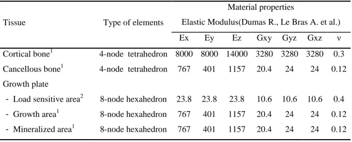
Table 3-1 Mechanical properties of the finite element model of vertebra T7 ... 43
Table 3-2 Material properties of the finite element model ... 65
Table 4-1 Mechanobiological growth under different loading conditions ... 75
Table 4-2 Simulation results under different loading condition using the energy-based model and Stokes's model. ... 76
Table 4-3 The modification of vertebral wedging in the coronal plane and of intervertebral rotation after two-year growth under different mechanical loads ... 79
LIST OF FIGURES
Figure 1-1 thoracic vertebra(Henry Gray F.R.S 1918) ... 5 Figure 1-2 lumbar vertebra(Henry Gray F.R.S 1918) ... 5 Figure 1-3 Intervetebral ligaments(Henry Gray F.R.S 1918) ... 6 Figure 1-4 vertebral cortical shell present different thicknesses in different regions(Thomas
Edwards W., Zheng Y. et al. 2001) (permission was approved) ... 8 Figure 1-5 primary ossification centers of a vertebra (Henry Gray F.R.S 1918) ... 11 Figure 1-6 Two secondary ossification center on the surfaces of the vertebral body (Henry
Gray F.R.S 1918) ... 11 Figure 1-7 Three secondary ossification centers on the tips of verterbral processes (Henry
Gray F.R.S 1918) ... 12 Figure 1-8 The position of the neuro-central junction (Henry Gray F.R.S 1918) ... 12
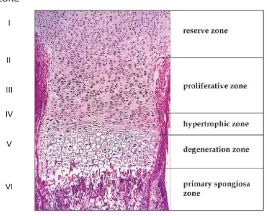
Figure 1-9 Different zones of a typical growth plate of a long bone (Burdan F. et al. 2009) (permission was approved) ... 15
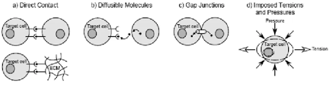
Figure 1-10 Four possible ways for inductive signal transmitting to target cells during mechanotransduction(Henderson J.H. and Carter D.R. 2002) (permission was approved) ... 20 Figure 1-11 Cobb angle measurement ... 31
Figure 1-12 Vertebral and discal wedging angle measurement (Modi H.N., Suh S.W. et al. 2008) (permission was approved)... 33 Figure 1-13 Measurement of vertebral heights of a vertebra reported by Parent (Parent S.,
Figure 1-14 The Stokes's axial rotation measurement. Determine a and b from vertebral image, and fix the width W and depth d for rotation calculation (Chi W.M. et al. 2006; Lam G.C., Hill D.L. et al. 2008) (permission was approved) ... 34
Figure 2-1 The logical relation of the thesis works ... 40 Figure 3-1 Finite element model of the vertebral body and the growth plate: (a) finite
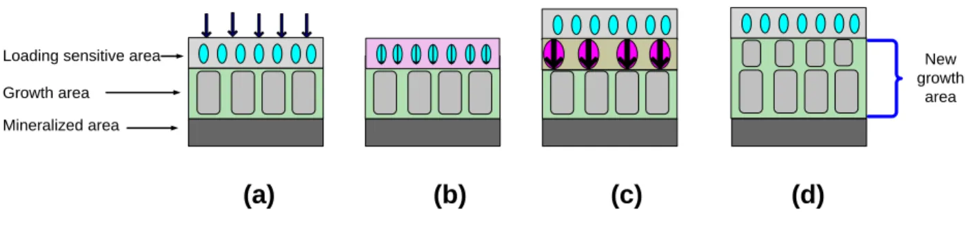
element model of the vertebral body (from a 12-year-old patient) including cortical and cancellous bone; (b) three-layer finite element model of the growth plate including loading sensitive, growth, and mineralized areas. ... 42 Figure 3-2 Conceptual model of the growth plate and bone growth process: (a) loads were
applied on the growth plate; (b) the loading sensitive area recorded mechanical stimuli; (c) biological and mechanobiological changes were triggered in the loading sensitive area; (d) new calcified bone left the loading sensitive area and deposited on the growth area, which combines to previous growth area. The height of new growth area increased, while the new loading sensitive area kept a constant height. ... 42 Figure 3-3 Stepwise simulation procedure of the growth of vertebra ... 46
Figure 3-4 Loading conditions: (a) tension of 0.2MPa for calibration purposes; (b) compression of 0.2MPa; (c) shear force of 82 N parallel to the vertebral surface; (d) combined tension of 0.2MPa and shear force of 82 N; (e) combined compression of 0.2MPa and shear force of 82 N ... 48 Figure 3-5 the energy-triggered mechanobiological growth process ... 49 Figure 3-6 Finite element model of vertbra T7 and its growth plate ... 59
Figure 3-7 Loading conditions: (a) testing tension of 0.1MPa for calibration purposes; (b) compression of 0.1MPa; (c) shear force of 82 N (equivalent to 0.15MPa)) parallel to the vertebral initial surface; (d) combined tension of 0.1MPa and shear force of 82 N; (e) combined compression of 0.1MPa and shear force of 82N. ... 60
Figure 3-8 The finite element model (FEM) of the functional unit T7-T8: (a) model of vertebrae and intervertebral ligaments; (b) model of disc and collagen fibers in the intervertebral disc; (c) model of cortical and cancellous bone; (d) model of the growth plate including three areas: loading sensitive area, growth area, and mineralized area.
... 64
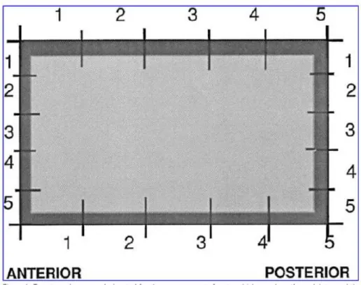
Figure 3-9 determination of the characteristic plane for endplate surface: (a) irregular shape of the growth plate surface after vertebral growth; (b) the characteristic plane for the irregular surface. The local coordinate system (LCS) for each vertebral growth plate was created based on the characteristic plane. ... 66 Figure 3-10 Measurement of the vertebral and discal wedging in the coronal plane. a1: T7;
a2: intervertebral disc T78. ... 68 Figure 3-11 Schematic diagram of simulated mechanical environments: (a) Pure axial
loading configuration: compression (maximum 0.35Mpa) and tension (maximum 0.35Mpa) with gradient distribution; (b) shear pressure (0.3Mpa); (c) shear pressure with gradient distribution (maximum 0.6Mpa); (d) torsion (0.3Mpa); (e) combined axial loading and shear. Axial loading has gradient distribution with maximal compression 0.35Mpa and maximal tension 0.35Mpa. ... 69
Figure 4-1 Calibration of the two models by applying a tension of 0.2MPa and carrying out one-year of growth. Similar growth is obtained for both models following calibration.
... 72
Figure 4-2 Growth distribution on the growth plate using Stokes’s and Carter’s model under following loading cases; (a) tension; (b) compression; (c) shear force; (d) combined tension/shear; (e) combined compression/shear. ... 73
Figure 4-3 Mechanobiological growth rates using Stokes’ and Carter’s models under the following loading cases: (a) compression; (b) shear force; (c) combined tension/shear; (d) combined compression/shear... 77
Figure 4-4 The modification of the geometry of the vertebral growth plate after one-year growth: (a) initial model of vertebral growth plate; (b) modified model after one-year growth. ... 77
Figure 4-5 Mechanobiological growth rates using Stokes’s and energy-based models under the following loading cases: (a) tension; (b) compression; (c) shear force; (d) combined tension/shear; (e) combined compression/shear. ... 78 Figure 4-6 simulated wedging angle of T7 (in the coronal plane) and intervertebral axial
rotation of T78 during two years growth under the following mechanical loads: (a) compression and tension (maximum 0.35Mpa) with gradient distribution; (b) shear (0.3Mpa); (c) torsion (0.3Mpa); (d) combined axial loading with gradient distribution and shear. The axial loading was a gradient compression and tension with maximal value of 0.35Mpa, and a shear pressure of 0.3Mpa. ... 80 Figure 4-7 Modification of the vertebral body morphology. (a) the initial morphology; (b)
wedging after two-year growth. ... 81
Figure 5-1 Schematic diagram of shear forces decomposition. (a) A shear force Fs is applied to a vertebra. This force can be transferred to a lower vertebra and is divided into two components: the shear force Fs1 and axial loading Fs2. The moment Ms is also generated for the force transferred; (b) the possible equivalent forces pattern generated from the moment. ... 88
Figure 5-2 Scoliotic vertebra growth characteristic and prediction of energy density distribution (a) The growth feature for a normal and scoliotic vertebra; (b) the growth distribution feature under asymmetric axial loading (Figure 3-11a) (c) the potential energy density distribution on the growth plate. The distribution is like a parabola with high densities on both edges and low density in the middle; (d) the energy distribution feature under asymmetric axial loading (Figure 3-11a) ... 93 Figure 5-3 Energy density distribution for each growth plate. ST7: T7 superior growth
plate is divided into six areas with similar width. These areas are numbered as 1 to 6 from left to right sides under postero-anterior view. The mean values of strain energy density for those six areas are calculated. (b) Energy distribution under axial loading with gradient distribution. (c) Energy distribution under shear pressure. (d) Energy distribution under combine axial loading and shear pressure. ... 94
LIST OF APPENDIX
APPENDIX A: EXPERIMENTAL STUDIES FOR MECHANOBIOLOGICAL GROWTH
... 121
APPENDIX B: FINITE ELEMENT MODELS OF THE SPINE ... 124 APPENDIX C: GROWTH SIMULATION USING THERMAL LOADING METHOD .. 128
NOMENCLATURE
e e b
a , = loading sensitive factors
f
D =morphological expression of growth plate tissues
d = displacement along the mechanical loading orientation
dv=volume of a micro element
E = elastic modulus g
E = energy contribution index )
(
u
F =function based on the variable of energy )
(
sI
F =function based on the variables of integrated stresses )
(
sS
F =function based on the variables of stresses G = shear modulus
f =mechanical force
Gm = longitudinal baseline growth for vertebrae
g
h = initial height of the growth area
i, j , k = the direction vector of axes for a local coordinate system
p p p j k i , , = principal direction e M =mechanosensing stimulus t
Me =tensor for mechanosensing stimulus
I M = mechanoregulation index p n = principal vector ) , , ; 3 , 2 , 1 (i j xyz pij
n = the component (x, y, z) of the direction vector for each principal vectori .
g
St =stimulus contribution index V= overall volume
U= strain energy
d
U = strain energy density dd
U = distortional strain energy density dv
U = dilatation strain energy density
W= mechanical work
x, y, z = axes of a local coordinate system l
le
= loading sensitivity factor for axial stress
yz xz xy , , = shear strain be = baseline growth me = mechanobiological growth ml
= mechanobiological growth for axial stress only
Tot
= overall deformity index
we = overall growth z y x , , = normal strains 3 2 1, , = principal strains = Poisson's ratio l
= axial (longitudinal) stress
z y
x
, , = normal stresses zz
= axial (longitudinal) stress 3 2 1, , = principal stresses oct = hydrostatic stress oct
= octahedral shear stress
yz xz
xy
, , = shear stresses
=overall displacement caused by mechanical loading l
= overall growth strain increment l
G
INTRODUCTION
Adolescent idiopathic scoliosis (AIS) is a three-dimensional deformity of the spine that develops during growth spurt with unknown cause (Lonstein J.E. 1994). Scoliotic vertebrae display geometric deformities including wedging and torsion due to abnormal growth. Mechanical loading was reported as stimulation to alter skeletal growth, modeling, and remodeling, and thus change bone morphology, histology, and material properties (Carter D.R. et al. 1996; Stokes I.A.F. 2002), as observed in scoliosis (Guo X. et al. 2003; Goldberg C.J. et al. 2008; Kotwicki T. and Napiontek M. 2008).
Bone growth in length is an endochondral ossification process via cartilage growth and ossification through proliferation and hypertrophy as well as extracellular matrix ossification (Villemure I. and Stokes I.A.F. 2009). It should be noted that bone growth in length takes place at the growth plate located at the epiphysis of long bones and vertebral endplates, which present high biological activity during adolescence and become thin and ossified in the adulthood. Bone growth is sensitive to the surrounding mechanical environment. Mechanical loads alter the proliferation and hypertrophy as well as the ossification of chondrocytes existing in the cartilaginous growth plate and thus modulate the growth rate (Alberty A. et al. 1993; Stokes I.A.F. et al. 2007).
Biological response of skeletal tissues to mechanical stimuli is termed as mechanobiology (Van Der Meulen M.C.H. and Huiskes R. 2002). The Wolff’s law and the Hueter-Volkmann principle are considered as basic concepts of bone remodeling and growth modulation respectively. Basically, the mechanobiological process includes: mechanosensing, mechanotransduction, and mechanoregulation (Silver F.H. and Bradica G. 2002; Huselstein C. et al. 2008). Those processes carry out the transformation from physical stimuli into biochemical reactions as well as final biological responses. Those responses exist in bone growth, modeling and remodeling. Although mechanical force is considered as general stimuli to trigger the generation and modification of skeleton tissues, the real mechanobiological process still is not clear, as well as the real nature of the growth modulation stimuli (stress, strain, energy, etc.).
Two analytical models of mechanobiological growth were developed based on two different methodologies: the model of Stokes (Stokes I.A.F. and Laible J.P. 1990; Stokes I.A.F. et al. 2006) and the one of Carter (Carter D.R. and Wong M. 1988; Stevens S.S. et al. 1999; Shefelbine S.J. and Carter D.R. 2004). Carter’s model initially described bone ossification pattern of a long bone and associated the hydrostatic compression stress and octahedral shear stress with the cartilage ossification (Carter D.R. and Wong M. 1988; Carter D.R. and Wong M. 1988). The octahedral shear stress is also termed as distortional energy stresses with promotion role on endochondral ossification, and the hydrostatic stress is defined as dilatational energy stress with inhibition function on ossification process. Carter’s theory was further applied on incorporation of endochodral growth and ossification and thus developed a mechanobiological growth model (Stevens S.S., Beaupre G.S. et al. 1999). This evolved model was later also integrated in finite element models of the proximal and distal femur to predict developmental hip dysplasia and femoral bicondylar angle due to the longitudinal growth of femur (Shefelbine S.J. et al. 2002; Shefelbine S.J. and Carter D.R. 2004; Shefelbine S.J. and Carter D.R. 2004). Stokes’s growth modulation model was initially derived from the hypothetical linear relationship between growth rate and the axial stress. This model was first established for ribs and for simulating scoliosis-related thorax deformity (Stokes I.A.F. and Laible J.P. 1990). Experimental works further supported this model and determined the model parameters (Stokes I.A.F., Aronsson D.D. et al. 2006). This model was later applied on the biomechanical model of the whole spine for investigating AIS caused by growth (Aubin C. E. 2002). This model has been integrated into a finite element model of the spine for simulating the vertebral body growth course and finding the mechanism of mechanobioloigy-triggered scoliosis (Villemure I. et al. 2002; Carrier J. et al. 2004; Villemure I. et al. 2004; Huynh et al. 2007). In addition, the neurocentral junction growth also used this model for studying the role of development of this anatomical part on AIS (Huynh, Aubin C. E. et al. 2007). The deformity of thorax also was studied using this model (Carrier J., Aubin C. E. et al. 2004). There is no study to investigate the differences and similarities of those two modeling techniques. The mechanobiological influences on the development of scoliosis triggered by non-axial and multi-axial stresses have not been investigated in published studies.
The spine, normal or pathologic, is subjected to complex dynamic loads, mainly in the axial direction, but also in the transverse plane. The non-axial loads were not accounted in Stokes’s model. This model and subsequent derived models (Villemure I., Aubin C. E. et al. 2002; Carrier J., Aubin C. E. et al. 2004; Huynh et al. 2007) so far was the only model applied on the biomechanical study of scoliosis. It is expected that mechanobiological effects on multi-axial loading on vertebral growth and generation of scoliotic vertebrae should be investigated. Both vertebral and intervertebral structures display complex geometric characteristics and thus result in complicated mechanical environments. Therefore, mechanobiological growth process and its impacts on scoliotic vertebrae development would allow identifying the pathomechanism of this disease.
This study targets on the investigation of mechanobiological contribution of multi-axial loading to development of scoliotic vertebrae. Finite element modeling technique is used to biomechanically reproduce the outcome of the development of growth-related scoliotic vertebrae. The growth-related technique combined with finite element model allowed to better understand potential mechanobiological risk of scoliosis.
This thesis is composed of seven chapters. The first chapter presents a review of relevant literature. The second chapter indicates the main objectives and hypotheses of this project. Chapter 3 presents study methodologies for this project. Chapter 4 shows simulation results. In Chapter 5, discussions for simulation results are present in response to proposed objectives and hypotheses. Finally, conclusions and recommendations for future studies are presented in Chapter 6.
CHAPTER 1.
LITERATURE REVIEW
1.1 Anatomy of spine
1.1.1 Spine structure
The spine, or vertebral column, is composed of five main segments: the cervical, thoracic and lumbar curvatures, as well as the sacrum and the coccyx. All of these curvatures of segments provide the structural support and protection for the spinal cord. The spine is composes of bony elements that are termed as vertebrae. Those elements are joined by interverbral discs, ligaments, and articular joins. There are twenty four vertebrae in the spine. The cervical curvature includes seven vertebrae, twelve in the thoracic curvature, and five in the lumbar curvature. In addition, the sacrum consists of five fused vertebrae and the coccyx is composed of three to five fused vertebrae (Maried N.E. 2003). Each segment composes of individual vertebrae, and the anatomy structure of vertebrae in each segment is different because of the structural variety in the different parts of the skeleton system.
vertebrae
A vertebra basically includes two anatomical components: the vertebral body on the anterior site, and the neural arch, a posterior part. The endplates are located at the superior and inferior sides of the vertebral body and composed of hyaline cartilage. The neural arch consists of a pair of pedicles and laminae, and seven processes including two transverse, one spinous, and a two articular both in superior and inferior sides of the vertebra. The joint which connect one vertebra to another vertebra above or below is called facet joint. The articular facets are located at the end of the articular processes and joined by the pars interarticularis. The facet joints control the spinal movement.
A thoracic vertebra has heart-shape body and the long spinous process that points down (Figure 1-1). The lumbar vertebrae have the largest bean-shape bodies and short spinous processes that point straight back (Figure 1-2).
Figure 1-1 thoracic vertebra(Henry Gray F.R.S 1918)
Figure 1-2 lumbar vertebra(Henry Gray F.R.S 1918) 1.1.2 Intervertebral structure
The vertebral bodies are connected by the intervertebral discs. The disc consists of the annulus fibrosus, tough rings of tissue, and the nucleus pulposus, a jellylike substance. The disc is firmly attached to the endplates of the vertebra. The discs allow for flexibility in the spine and absorb shock. In a young person, the discs have a high percentage of water (about 90%), and the disc is spongy and compressible. As the age increases, the disc becomes harder and less compressible.
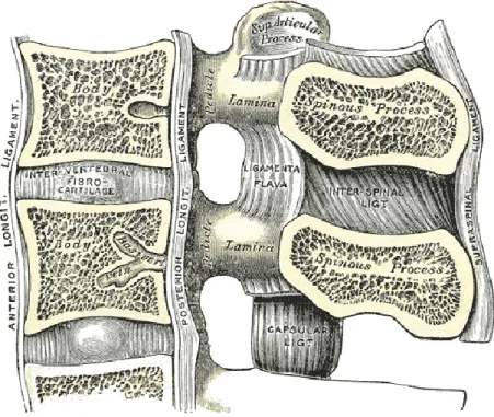
Figure 1-3 Intervetebral ligaments(Henry Gray F.R.S 1918)
Ligaments and tendons are soft collagenous tissues. Ligaments connect bone to bone and tendons connect muscles to bone. Ligament contains collagen fibrils, proteoglycan matix, and fibroblasts (biological cells) that are arranged in parallel rows. The biomechanical function of ligaments is to carry the tensile force from one bone to another bone. A tendon has a similar hierarchical structure to the ligament, but it has slightly higher volume fraction and organization than the ligament. A tendon is able to transfer forces from a muscle to a bone and carry compressive forces. The vertebral ligaments are tough, non-elastic bands (Figure 1-3). They hold the vertebrae together and control the amount of movement of a joint. The ligaments are able to absorb energy coming from the body motion and to protect the neural and skeletal system from injury. There are 9 spinal ligaments connected to the vertebrae. The anterior longitudinal ligament (ALL) attached on the anterior side of each vertebra and the intervertebral disc goes through the entire length of the spine. The posterior longitudinal ligament (PLL) also goes through the entire length of the spine and sticks to the posterior side of each vertebral body and intervertebral disc. The ligamentum flavum (LF) links the laminae between adjacent vertebrae. The intertransverse ligaments (ITL) join transverse processes on adjacent vertebrae both in left
and right sides. The interspinous ligaments (Huselstein C., Netter P. et al.) connect the spinous processes of adjacent vertebrae. The supraspinous ligament (SSL) extends through the entire spine and attaches to the tip of spinous processes. The capsular ligaments (CL) link each pair of facet joints and attach the peripheral sides of the facet joint.
1.2 Vertebral bone and cartilage
The spinal skeletal tissues consist of vertebral bony, cartilaginous, and soft collagenous tissues. Vertebral bony tissues include the cortical bone, which exists in the outer shell of the vertebral body, and compacted cancellous (or trabecular) bone, which fills the vertebral internal body. The cartilaginous tissue exists in the endplate and intervertebral discs. The intervertebral ligaments are composed of collagenous tissues.
Cortical and trabecular bones
Cortical, or compact bone, has high mineral content (approximately 70%) and high occupancy in total bone mass (about 80%). The principle function of the cortical bone is mechanical support. Trabecular (cancellous) bone consists of plates and bars of bone adjacent to small, irregular cavities containing marrows. Trabecular bone serves to reduce the skeletal weight but keep effective strength. The multiple surfaces of the trabeculae play an important role on bone remodeling (Netter F.H. 1987).
Vertebral cortical shell varies at each level of the spine, and the material property of vertebral cortex is also non-uniform in different sites at one vertebra (Figure 1-4)(Thomas Edwards W. et al. 2001; Schmidt H. et al. 2007). The thickness range from 0.25mm to 1.43mm as reported in (Thomas Edwards W., Zheng Y. et al. 2001). In addition, the different regions of a vertebral body have different thicknesses. Bone tissues at the vertebral body present high strength, while the posterior bony tissues are comparatively weak material(Schmidt H., Heuer F. et al. 2007). In general, the morphology of vertebral bone presents high non-linearity and depends on spinal level, anatomic site, age, gender, etc.
Figure 1-4 vertebral cortical shell present different thicknesses in different regions(Thomas Edwards W., Zheng Y. et al. 2001) (permission was approved)
Bone cells
Bone tissues present complex, living, constantly changing properties, and bone development and maintenance is carried out by the cellular component (Buckwalter J.A. and Cooper R.R. 1987; Andreassen T.T. and Oxlund H. 2001). There are three kinds of cells involved in the bone development: osteoblasts, osteocytes and osteoclasts. Osteoblasts are bone-forming cells, and osteoclasts break down and reabsorb bone. Osteocytes are mature bone cells, which account for 90% of the human skeleton system (Sommerfeldt D.W. and Rubin C.T. 2001).
Osteoblasts
Ostroblasts are the cells with cuboidal shape and about 8 weeks of lifespan in human and located at the bone surface. These cells have functions for forming the extracellular matrix and regulate its mineralization, during which time it lays down 0.5-1.5 μm³/day osteoids (Buckwalter J.A. and Cooper R.R. 1987; Price J.S. et al. 1994). The activities of osteoblasts are close related
to extensive cell-matrix and cell-cell contacts by some special proteins and receptors (growth factors) for maintaining the cellular function and responding to metabolic and mechanical stimuli. There is accumulating evidence that these cells are sensitive to the requirement of bone formation and direct the site of new bone apposition functionally(Buckwalter J.A. and Cooper R.R. 1987).
Osteoclasts
Osterclast cells derived from hematopoietic stem cells with high migratory, multinucleated, and polarized properties. The main characteristic of these cells is to resorb fully mineralized bone. An activated osteclast is able to resorb 200,000μm³/day mineralized bone(Sommerfeldt D.W. and Rubin C.T. 2001; Zvi B.S. 2007).
Osteocytes
Osteocytes derived from osteoblast but are distinctly different in morphology and function, and they are the most abundant cells in bone. As principal cells in adult bone, osteocytes are smaller in size than osteoblasts and have an increased nucleus to cytoplasm ratio (Buckwalter J.A. and Cooper R.R. 1987; Zvi B.S. 2007).
Cartilaginous tissues
Cartilaginous tissue is a firm and elastic skeletal tissue. It consists of matrix and cells. The matrix contains chondroitin sulfate, a kind of ground substance, and fibers that bind with water. The cellular elements of cartilage are termed as chondrocytes which lie in spaces called lacunae and surrounded by the perichondrium fibrous. There are two basic forms of cartilage existing in the spine:
Hyaline cartilage. A kind of cartilage with translucent matrix. It exists in the endplate and tips of the spinal processes. An important role of hyaline cartilage is to permit the growth.
Fibrous cartilage: cartilage containing collagen fibers. It exists in the intervertebral disks.
1.3 Vertebra development
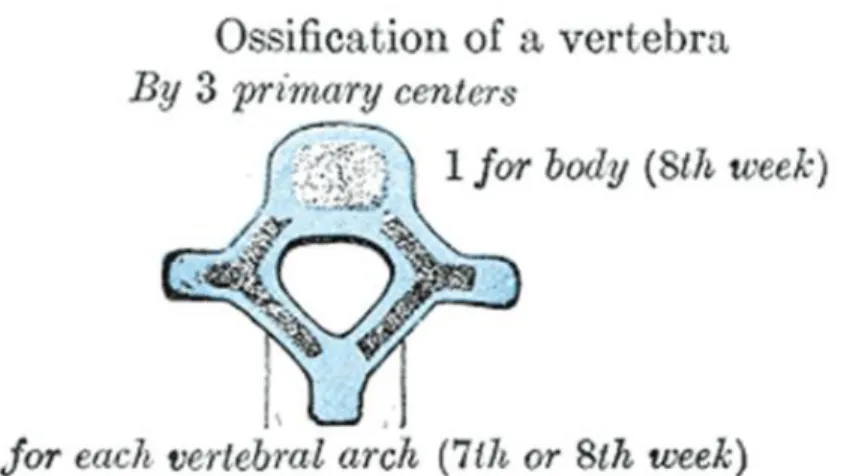
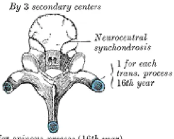
The vertebrae begin to develop in humans at 4 weeks after conception. The most important biological process during the development of the vertebral column is to create a flexible enclosure to allow continuous growth of the neural components developing slower and later (Sommerfeldt D.W. and Rubin C.T. 2001). The cartilaginous vertebrae are formed during embryo. During the vertebrae development, the cartilage are replaced by bone which is called bone ossification or bone stage development spanning from 7 weeks to 25 years (Sommerfeldt D.W. and Rubin C.T. 2001). There are three primary ossification centers in each cartilaginous vertebra: two for the vertebral arch and one for the body (Maat G.J. et al. 1996)(Figure 1-5). Before puberty, there are five secondary ossification centers generating: two for superior and inferior surfaces of the vertebral body (Figure 1-6), one on the tip of each transverse process, and one on the tip of the spinous process (Figure 1-7). These secondary centers fuse the rest of the bone about the age of twenty-five (Henry Gray F.R.S 1918). In addition, there are two cartilaginous growth plates located between the vertebral centrum and neural arch both on left and right sides (Figure 1-8). Those plates were termed as the neurocentral junction(NCJ), which is bipolar plate and contributes to the development of the vertebral body and the posterior neural arch (Vital J.M. et al. 1989; Yamazaki A. et al. 1998; Rajwani T. et al. 2005). The NCJ presents maximal activities at the age around 5-6 years when it shows the maximal contribution to the morphology of a vertebra. It is closed around 11-16 years during adolescent and could be identified as the boundary of the two ossification centers, the vertebral centrum and the neural arch (Vital J.M., Beguiristain J.L. et al. 1989; Maat G.J., Matricali B. et al. 1996; Yamazaki A., Mason D.E. et al. 1998; Rajwani T. et al. 2002).
There are two kinds of ossification: intramembranous and endochondral ossification (Cohen M.M.Jr. 2006).
Intramembranous ossification
This ossification involves the replacement of sheet-like connective tissue membranes with bony tissue, which is termed as intramembranous bones. Intramembranous ossification is
the characteristic way to form the flat bones of the skull and some of the irregular bones (Atchley W.R. and Hall B.K. 1991; Cohen M.M.Jr. 2006)
Endochondral ossification
The endochondral ossification is the process of the replacement of hyaline cartilage with bone tissue, like for the development of the axial and appendicular skeleton (Cohen M.M.Jr. 2006).
Figure 1-5 primary ossification centers of a vertebra (Henry Gray F.R.S 1918)
Figure 1-6 Two secondary ossification center on the surfaces of the vertebral body (Henry Gray F.R.S 1918)
c
Figure 1-7 Three secondary ossification centers on the tips of verterbral processes (Henry Gray F.R.S 1918)
Figure 1-8 The position of the neuro-central junction (Henry Gray F.R.S 1918)
Bone development process includes bone growth, bone modeling and remodelling (Jee W.S.S. and Frost H.M. 1992; Doskocil M. et al. 1993; Cowin S.C 2004; Marotti F. et al. 2004).