UNIVERSITÉ DE MONTRÉAL
CMOS AND MEMS BASED MICROSYSTEMS FOR MANIPULATION AND
DETECTION OF MAGNETIC BEADS FOR BIOMEDICAL APPLICATIONS
YUSHAN ZHENG
DÉPARTEMENT DE GÉNIE ÉLECTRIQUE ÉCOLE POLYTECHNIQUE DE MONTRÉAL
THÈSE PRÉSENTÉE EN VUE DE L’OBTENTION DU DIPLÔME DE PHILOSOPHIAE DOCTOR
(GÉNIE ÉLECTRIQUE) NOVEMBRE 2014
UNIVERSITÉ DE MONTRÉAL
ÉCOLE POLYTECHNIQUE DE MONTRÉAL
Cette thèse intitulée :
CMOS AND MEMS BASED MICROSYSTEMS FOR MANIPULATION AND DETECTION OF MAGNETIC BEADS FOR BIOMEDICAL APPLICATIONS
présentée par : ZHENG Yushan
en vue de l’obtention du diplôme de : Philosophiae Doctor a été dûment acceptée par le jury d’examen constitué de :
M. LAURIN Jean-Jacques, Ph. D., président
M. SAWAN Mohamad, Ph. D., membre et directeur de recherche M. MARTEL Sylvain, Ph. D., membre
DEDICATION
ACKNOWLEDGEMENTS
I would first like to thank my supervisor, Professor Mohamad Sawan for all his support, encouragement and guidance during my Ph.D. research life in Polystim Neurotechnologies Laboratory.
I would also like to thank Professor Jean-Jacques Laurin, Professor Sylvain Martel, and Professor Pierre Haddad for their suggestions at the early stage of my Ph.D. research. Their resourceful experience helped me get rid of some unnecessary detours in research.
Thanks are due to three intern students I guided, Sara Bekhiche, Abir Mannai and Cyril Jacquemod, for their hard work to contribute to my research project.
I thank all staff members and colleagues of Polystim Lab who helped me during my stay in Polytechnique Montreal. Special thanks are due to the following people for their helps and collaborations: Marie-Yannick Laplante, Laurent Mouden, Rejean Lapage, Jean Bouchard, Arash Moradi, Sami Hached, Saeid Hashemi, Faycal Mounaim, Amine Miled, Mohamed Zgaren, and Nan Li.
I am also grateful for the support from the Canada Research Chair in Smart Medical Devices, the Natural Sciences and Engineering Research Council of Canada, CMC Microsystems and the scholarship from China Scholarship Council.
Finally, I want to express the deepest gratitude to my family for their love and encouragements during my study.
RÉSUMÉ
Les micro et nano billes magnétiques dédiées à l'étiquetage des bio-particules attirent de plus en plus d'intérêt dans de nombreuses applications environnementales et sanitaires, tels que l'analyse de gènes, le transport des médicaments, la purification et l'immunologie. Les dimensions réduites et la haute sensibilité des billes magnétiques rendent leurs manipulations à haute précision possibles. Leur simplicité de suivi dans le milieu biologique et leur biocompatibilité permettent d’effectuer des détections rapides et à haute sensibilité pour des applications in vivo et in vitro. L'utilisation traditionnelle des billes magnétiques prend place dans un laboratoire se servant du matériel encombrant et dispendieux. Avec le développement de la technologie de microfabrication, des billes magnétiques peuvent être traitées dans un microsystème, plus précisément, dans une structure laboratoire sur puce (LoC). La combinaison microfluidique et microélectronique offre des possibilités d’autoévaluation, ce qui peut augmenter l'efficacité du travail.
Cette thèse est orientée vers de nouvelles approches pour la manipulation et la détection de bio-particules se servant de la technologie de microsystèmes basées sur des structures microelectroniques et microfluidiques et en utilisant des marqueurs de billes magnétiques. Basé sur un réseau de microbobines à la fois comme une source de champ magnétique et un capteur inductif, le microsystème proposé est réalisé grâce à l'efficacité de fabrication de structures CMOS-MEMS, ainsi que des circuits intégrés dédiés CMOS de haute performance afin d'obtenir un rendement élevé de manipulation et de détection de billes magnétiques.
Plusieurs défis ont été analysés dans la mise en œuvre de ces microsystèmes et des solutions correspondantes fournies. Plus précisément, la conception et la mise en œuvre d'une plate-forme contrôlée en température en format portable sont d'abord présentées, dans un effort réalisé pour résoudre la question de la chaleur par effet Joule lors de l'application du réseau de microbobines comme une source de champ magnétique dédié à la manipulation de billes magnétiques. Une plateforme similaire à cette dernière a été améliorée pour effectuer une analyse magnétique immunologique, en ajoutant des circuits de détection par des billes magnétiques. De plus, des IgG et anti-IgG de souris ont été utilisés dans des expériences pour vérifier les performances de détection de la plateforme de microsystème proposé. En outre, un substrat de silicium intégrant une structure MEMS et incorpore à la fois un microcanal microfluidique et un réseau de
microbobines sur une seule puce a été conçu et fabriqué suivant l'analyse par éléments finis (FEA) de résultats de simulation. Cette dernière structure a été testée à l'aide de bio-particules attachées à des billes magnétiques. Cette structure monolithique est susceptible d'être utilisée pour des applications in vivo.
ABSTRACT
Magnetic micro/nano beads as labels of bio-particles have been attracting more and more interest in many environmental and health applications, such as gene and drug delivery, purification, and immunoassay. The miniature size and high sensitivity of magnetic bead allow accurate manipulation, whereas its high distinguishability from biological background and biocompatibility make fast and high sensitivity detection possible for in vitro and in vivo applications. Traditional employment of magnetic beads is done in laboratory environment with the assist of bulky and expensive equipment. Thanks to the development of microfabrication technology, magnetic beads therefore can be handled on a microsystem, more specifically, a Lab-on-Chip (LoC). The combination of microfluidics with microelectronics offers the possibility of automatic analyses, which can liberate the labor and increase the efficiency.
This thesis focuses on new approaches for bio-particles manipulation and detection on microelectronic/microfluidic hybrid microsystems using magnetic beads as labels. Based on planar microcoil array as both magnetic field source and the front-end inductive sensor, the proposed microsystems can take advantage of the massive producible CMOS/MEMS fabrication process, as well as the customized high performance CMOS circuits, to achieve a high efficient magnetic beads manipulation and a quantitative detection.
Several challenges in implementing such microsystems are analyzed and corresponding solutions are provided. Specifically, the design and implementation of a temperature controllable LoC platform in portable format is firstly presented, for the sake of resolving the Joule heat issue when applying microcoil array as magnetic field source in magnetic beads manipulation. The similar platform is then improved to be used for magnetic immunoassay, by adding magnetic beads sensing circuits. Mouse IgG and anti-mouse IgG are employed in experiments to verify the detection performance of the proposed microsystem platform. Additionally, a fully integrated silicon substrate MEMS chip which integrates both microfluidic channel and microcoil array on a single chip is designed and fabricated following the Finite Element Analysis (FEA) simulation results and tested using bio-particles attached magnetic beads. This monolithic chip has the potential to be applied for in vivo applications.
TABLE OF CONTENTS
DEDICATION ... iii ACKNOWLEDGEMENTS ... iv RÉSUMÉ ... v ABSTRACT ... vii
TABLE OF CONTENTS ... viii
LIST OF TABLES ... xi
LIST OF FIGURES ... xii
LIST OF ABBREVIATIONS ... xii
INTRODUCTION ... 1
Motivation ... 1
Research Objectives ... 2
Research Contributions ... 3
Thesis Organization ... 5
CHAPTER 1 THEORETICAL FOUNDATIONS OF MAGNETIC BEADS MANIPULATION AND DETECTION ... 6
1.1 Superparamagnetic Beads ... 6
1.2 Forces on Magnetic Beads in Liquid ... 9
1.3 Magnetic Field Generated by Planar Microcoil ... 10
1.4 Joule Heat Generated by Microcoil ... 13
1.5 Magnetic Beads Detection ... 14
CHAPTER 2 STATE OF THE ART OF THE LAB-ON-CHIP MICROSYSTEMS U SING MA GN ETIC B EAD S ... 18
2.1 Labeled and Non-labeled Manipulation and Detection of Bioparticles-A Comparison 18
2.2 Microsystems for Magnetic Beads Manipulation ... 20
2.3 Microsystems for Magnetic Beads Detection ... 26
2.3.1 GMR Sensor ... 26
2.3.2 Hall Sensor ... 28
2.3.3 NMR Sensor ... 30
2.3.4 Inductance Detection Based Magnetic Sensor ... 32
2.4 Microsystems Packaging Techniques ... 34
CHAPTER 3 A TEMPERATURE CONTROLLABLE PLATFORM FOR MAGNETIC BEADS MANIPULATION ... 39
3.1 Introduction ... 39
3.2 Planar Microcoil Array Based Temperature-controllable Lab-on-Chip Platform ... 40
3.2.1 Abstract ... 40
3.2.2 Introduction ... 40
3.2.3 Joule Heat Effect Analysis and Simulation ... 42
3.2.4 Current Supply Circuit ... 47
3.2.5 Device Architecture and Fabrication ... 49
3.2.6 Experimental Results ... 52
3.2.7 Conclusion ... 56
CHAPTER 4 A MICROSYSTEM FOR MAGNETIC IMMUNOASSAY BASED ON PLANAR MICROCOIL ARRAY ... 57
4.1 Introduction ... 57
4.2 A Microsystem for Magnetic Immunoassay Based on Planar Microcoil Array ... 58
4.2.1 Abstract ... 58
4.2.3 Microcoil Sensor ... 62
4.2.4 Integrated CMOS Chip Design ... 67
4.2.5 Microsystem Prototype and Experiments ... 75
4.2.6 Conclusion ... 80
CHAPTER 5 A NOVEL BIO-MEMS CHIP FOR MAGNETIC BEADS APPLICATIONS ... ... 81
5.1 Introduction ... 81
5.2 A BioMEMS Chip with Integrated Micro Electromagnet Array towards Bio-particles Manipulation ... 82
5.2.1 Abstract ... 82
5.2.2 Introduction ... 82
5.2.3 Design and Fabrication ... 83
5.2.4 Controllable Magnetic Field by Microcoil Array ... 87
5.2.5 Experiments ... 91
5.2.6 Discussion ... 94
5.2.7 Conclusion ... 94
CHAPTER 6 GENERAL DISCUSSION ... 96
CHAPTER 7 CONCLUSION ... 99
7.1 Conclusion ... 99
7.2 Recommendation for Future Work ... 100
LIST OF TABLES
Table 1 MATERIAL PARAMETERS FOR MODELLING AND SIMULATIONS ... 43 Table 2 COMPARISON WITH STATE-OF-THE-ART RESEARCHES ... 94
LIST OF FIGURES
Figure 1.1 Diagram of (a) a red blood cell, (b) a magnetotactic bacterium, (c) a cell with digested magnetic nanoparticles, and (d) a cell with magnetic micro/nano particles attached to the surface [9] ... 6 Figure 1.2 Structure of a magnetic bead showing its polymer shell, the attached bioparticles and
the contained superparamagnetic nanomagnets in the presence (a) and in the absence (b) of external magnetic field. ... 7 Figure 1.3 Simplified schematic diagram of the main directions of the most important forces
acting on a magnetic bead. ... 9 Figure 1.4 Magnetic field generated by one loop of microcoil ... 11 Figure 1.5 (a)Planar spiral coil model: wire thickness 1um, inner diameter 60 µm, outer diameter 400um, and the current passing through the coil 100mA; (b) and its 3D model in FEA software and the magnetic field distribution... 12 Figure 1.6 Magnitude of total magnetic flux density (a) along a line parallel to the surface of the microcoil and located 20 µm above it; (b) along a line perpendicular to the surface of the microcoil and located at the center of it. ... 12 Figure 1.7 Magnetic field distribution for different geometrical planar microcoils: a) planar coil
models, each coil occupies an area of 450 um by 450 um, carrying a current of 30 mA; b) corresponding magnetic field distribution on the z = 1 um plane. ... 13 Figure 1.8 Planar microcoil for monitoring magnetic susceptibility: a) the microcoil and magnetic particles with toxins captured; b) high frequency equivalent circuit model; c) cross sectional view of a microcoil showing the magnetic field distribution. ... 15 Figure 2.1 Magnetic bead separator employing permanent magnets[54]. ... 20 Figure 2.2 A microsystem combining permanent magnets and electromagnets. Cu current lines
are buried in the back side of the substrate at the positions indicated by the white lines. ... 21 Figure 2.3 A summary of the performance of various planar electromagnets. Row 1: a schematic view of the microcoil; row 2: image under optical microscope; row 3: the simulated
magnetic flux density profile; row 4: schematic of the magnetic bead trapping profile and; row 5: optical image of the magnetic beads trapped by corresponding microcoils [56] ... 22 Figure 2.4 (a) Schematic of the microsystem with the fluidic chamber on top of the coil and
pillar; (b) Prototype of final fluidic device with chip inserted in. The size of the fluidic chamber is 10mm×5mm×0.1mm. The fluidic inlet and outlet, with inner diameter of 0.5 mm. The fluidic block is connected to a programmable syringe pump fitted with a 1 ml syringe[61]. ... 23 Figure 2.5 Microcoil array for magnetic beads manipulation. By controlling currents in the
microcoils, many different magnetic field patterns can be generated. To generate the required fields, current pulses with appropriate values and directions are alternatively applied to two neighboring microcoils[62]. ... 24 Figure 2.6 An open cavity microsystem integrating CMOS coil array for individual magnetic
bead manipulation [51]. ... 25 Figure 2.7 Schematic of a GMR based magnetic flow sensor design [54] ... 27 Figure 2.8 A conceptual schematic view of a Hall sensor for single magnetic particle
detection[69]. An external magnetic field is applied to polarize the magnetic bead which produces a stray magnetic field. ... 29 Figure 2.9 Conceptual drawing of the NMR relaxometer and its proximity assay [59]. (a) The
bulk spin-spin relaxation time T2 for water molecules without test samples. (b) The relaxation time is reduced with monodispersed magnetic particles. (c) The target molecule i.e., proteins, trigger the proximity assay and lead to aggregation of magnetic particles to form clusters, which further decrease the relaxation time of the water molecules. ... 31 Figure 2.10 A microsystem for CMOS frequency-shift-based magnetic sensor array with
integrated microfluidic structures (left) and the zoom-in view of one differential sensing pair (right) [59]. ... 32 Figure 2.11 Inductance detection based magnetic sensor for detecting DNA [64] ... 33 Figure 2.12 Application of PDMS in microfluidic chip [60] ... 35
Figure 2.13 Fabrication procedure of DWFP technique: (a) ink deposition, (b) encapsulation in
epoxy and (c) ink extraction [81]. ... 36
Figure 2.14 A Sensonit glass substrate based hybrid microsystem[69]. ... 37
Figure 3.1 Magnetic beads as solid phase carriers for bioparticles manipulation ... 41
Figure 3.2 The proposed closed-loop temperature control system. ... 44
Figure 3.3 3D Model of microcoil with channel and substrate in CoventorWare: (a) complete model; (b) Substrate is hidden to show microcoil array. ... 44
Figure 3.4 Thermal propagation analysis when the input of a microcoil is constant-frequency square-wave current. ... 45
Figure 3.5 Maximum temperature variation for different current inputs: (a) DC input; (b) Constant frequency input---duty cycle 1:2 and frequency 1Hz; (c) Variable frequency input ---duty cycle 1:2 and frequency 1Hz from 0 to 2.75s; duty cycle 1:5 and frequency 1Hz from 0 to 2.75s; duty cycle 1:5 and frequency 1 Hz after 2.75s. ... 46
Figure 3.6 Schematic of the proposed bidirectional current source. ... 48
Figure 3.7 Post layout simulation of bidirectional current supply circuit. ... 49
Figure 3.8 Architecture of the microcoil array based LoC platform. ... 50
Figure 3.9 The proposed polyimide substrate LoC device: (a) Hexagonal microcoil chip with microfluidic structure; (b) Bottom view showing the heat dissipation layer and CMOS chip; (c) Microphotograph of the CMOS chip; Die size 0.85mm by1.15mm; (d) Square microcoil array. ... 50
Figure 3.10 Individual magnetic bead manipulated by two adjacent microcoil: (a)The targeted observation area in the microcoil array; (b) Original position of the targeted magnetic bead; (c) Magnetic bead was polarized and attracted toward the lower coil; (d)-(g) Magnetic bead was attracted toward the upper microcoil. ... 54
Figure 3.11 Mass beads trapping experiment showing the magnetic beads in solution concentrated in the active coil region. ... 55
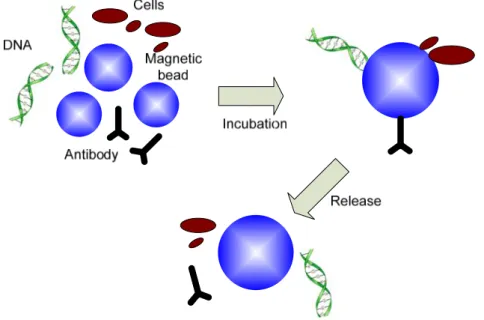
Figure 3.12 Monitored temperature variation during the whole magnetic beads trapping experiment. ... 55 Figure 4.1 Sensor network involving microsystem for monitoring environmental toxins. ... 59 Figure 4.2 Flow chart for a typical magnetic immunoassay: a) antibodies are patterned on bottom surface of substrate; b) under-test sample solution is introduced, specific antigens will be captured due to antigen-antibody reaction, and other molecules in solution are flushed out; c) magnetic beads labeled antibodies are injected, a sandwich structure is formed. Superfluous beads that are not bound are flushed out. Finally the amount of magnetic beads that can be detected by sensor reflects the amount of antigen. ... 60 Figure 4.3 Main components of the proposed Magnetic Immunoassay microsystem. ... 62 Figure 4.4 Planar microcoil as magnetic sensor: a) the concept of microcoil and magnetic
particles with toxins captured; b) high frequency equivalent circuit model; c) cross sectional view of a microcoil showing the total magnetic field distribution; d) our fabricated microcoil with inductance 210nH, DC resistance 0.65Ω and Q factor 75 at 200 MHz. ... 64 Figure 4.5 Block diagram of the achieved CMOS chip. ... 67 Figure 4.6 Schematic of cross coupled LC oscillator and self biased buffer circuit and simulation results: a) schematic; b) transient simulation result; c) phase noise simulation results. ... 69 Figure 4.7 Bidirectional multiple steps current supply circuit: a) schematic and b) post-layout
simulation result ... 72 Figure 4.8 On-chip PTAT sensor circuit: a) schematic showing the temperature monitor and
control loop; b) simulation result. ... 74 Figure 4.9 Prototype of the microsystem: a) The view of platform showing the setup of 96 wells microplate, microcontroller board, LCD display and power supply circuits ; b) The sensor board under the microplate; c) The backside view of sensor board showing the mount of our designed CMOS chip; d)The micrograph of our designed CMOS chip. 76
Figure 4.10 Experiments results: a) real time data record showing output frequency v.s. time; b) extracted data showing frequency shift v.s. density of mouse IgG. ... 77 Figure 4.11 Microscopic view showing the attached different densities of magnetic beads in
different microplate wells, the corresponding mouse IgG added in wells are: a)1ng/ml; b)10ng/ml; c)100ng/ml; d)10ug/ml. ... 79 Figure 5.1 Main fabrication flow used in this design: a) deposition and pattern of isolation oxide, sacrifice oxide and nitride layer 1 and 2; b) deposition and pattern of metal layer(coil structure), anchor metal layer(connection between polysilicon and metal) and polysilicon layer; c) removal of oxide layer by HF solution to form the suspended structure; d) KOH silicon etching to form the trench; e) top view of final device model in Coventorware to show the whole device and microchannel. ... 86 Figure 5.2 Total magnetic field flux density distribution for different geometrical planar
microcoils: a) planar coil models, each coil occupies an area of 450 um by 450 um, carrying a current of 30 mA; b) corresponding magnetic field distribution on the z = 1 um plane. ... 87 Figure 5.3 a) Total magnetic field flux density distribution on x-z plane where y=0; b) magnetic flux density in x direction where z=25 µm. ... 88 Figure 5.4 Magnetic field distribution of coil array: a) Four-coil array model in Ansys. Width 8
um, space 8 um, outer diameter 450 um, inner diameter 80 um; b) applying current in four coils with same amplitude and direction, mode AAAA; c) applying current with same amplitude but opposite direction for adjacent coils, mode ABAB; d) applying same amplitude current to four coils but with same direction in the top two and opposite direction to the bottom two, mode AABB; e) x directional magnetic field distribution, mode ABAB; f) z directional magnetic field distribution, mode ABAB. (A and B represent the opposite current direction; figure b, c and d share the top legend, whereas e and f share the bottom one). ... 90 Figure 5.5 Micrograph of MEMS chip: a) microcoil and bonding wires; b) inlet/outlet of
microfluidic; c) micropipette absorbing liquid containing magnetic particles; d) micropipette dispensing liquid from inlet; e) magnetic particles near the outlet of microchannel. ... 92
Figure 5.6 Experimental results showing the normalized trapping ratios versus current consumption for single, double and triple activated coil. Trapping ratio of 90% can be achieved for triple coil regime while consuming a current of 40 mA. ... 93 Figure 7.1 Concept of an automated PCR chip with magnetic immunoassay for pathogens
LIST OF ABBREVIATIONS
LoC Lab on Chip
CMOS Complementary metal-oxide semiconductor MEMS Micro electro-mechanical systems
PMOS P channel metal-oxide-semiconductor field effect transistors NMOS N channel metal-oxide-semiconductor field effect transistors FEA Finite Element Analysis
PoC Point of care
GMR Giant magnetoresistance NMR Nuclear magnetic resonance DC Direct current
AC Alternative current DEP Dielectrophoresis
SPAD Single photon avalanche diode MIA Magnetic immunoassay PDMS Polydimethylsiloxane EDA Electronic design automation
ELISA Enzyme-linked immunosorbent assay PCB Printed circuit board
PTAT Proportional to absolute temperature PCR Polymerase chain reaction
TDC Time to digital convertor PLL Phase lock loop
MCU Micro control unit MUX Multiplexier
DWFP Direct wirte fabrication process µTAS Micro total analysis system RT Room temperature
INTRODUCTION
Motivation
Microelectronic/microfluidic hybrid microsystems, as a branch of Lab on a Chip (LoC), has been creating more and more interests in many application fields, including point of care (POC) diagnostics, life science and environmental applications. These microsystems share the same advantageous of LoC over the traditional macroscale in-lab methods, including compact size, decreased reagent volumes, increased functionality, disposability, high throughput analyses. Moreover, the combination of microfluidics with microelectronics offers the possibility of turning the time-consuming and/or labor-intensive processes towards high efficient automated analyses. Additionally, thanks to the development of microfabrication technology, many new applications that are difficult to be realized in macro scale can be achieved on emerging hybrid microsystems, because the interaction of microsystems with bioparticles opens a new window to novel methods of medical diagnostics and environmental monitoring.
Various microsystems built by different mechanisms for bioparticles manipulation and detection have been reported, such as mechanical structures based micro-tweezers for manipulation and micro-cantilever for detection[1][2], electric field based dielectrophoresis (DEP) manipulation and resistive/capacitive detection[3][4], magnetic field based magnetic beads labeled bioparticles manipulation and detection[5][6], as well as optical field based light beam for manipulation and fluorescence labeled bioparticles detection[7][8]. Among these microsystems, the ones using magnetic micro/nano beads as labels of bioparticles have been attracting great attention in many environmental and health applications, such as gene and drug delivery[9], purification[10], and immunoassay[11]. As the labels of bioparticles, magnetic beads can be accurately manipulated due to their miniature size and high magnetic susceptibility. Moreover, their high distinguishability from biological background and their biocompatibility make fast and high sensitivity detection possible for in vitro and in vivo applications.
Conventional devices for magnetic beads labeled bioparticles manipulation exploit external ferromagnets or simple topological on-chip electromagnets for generating magnetic field, thus they suffer from some drawbacks including low power efficiency, high cost, inaccurate manipulation, and more difficulties for miniaturization. Therefore, the design of optimized
on-chip electromagnets for high efficiency and high flexibility manipulation are in demand.
Furthermore, in electromagnetic LoC applications, the inevitable Joule heating effect is widely mentioned but usually treated by an additional complicated cooling system, which highly increases the system complexity and total power consumption. In fact, it is possible to reduce the Joule heat by improving the design of electromagnets and applying advanced control algorithms, without increasing the complexity of hardware system design, thus the “overheating spot” issue in conventional device can be avoided and the temperature of liquid can be always maintained within the safe range to bioparticles.
Additionally, for the detection of bioparticles using magnetic beads as labels, despite a few microsystems have been reported, there are several challenges yet to be overcome. The first is the design of a high performance front-end magnetic sensor and its sensing circuits, which should respect both sensitivity and linearity, for the sake of quantitative analysis. Moreover, many of the conventional microsystems exploit expensive materials and non-standard fabrication process to achieve the magnetic sensor, thus they are not suitable for large scale deployment for multiple sites monitoring in environment or low cost PoC diagnostics. Furthermore, the packaging technique is also very challenging because a robust biological interface will definitely facilitate the device setup and testing process, thus shorter detection time and more reliable results can be achieved.
Research Objectives
The main objective of this research is to study new approaches for bioparticles manipulation and detection on microelectronic/microfluidic hybrid microsystems using magnetic beads as labels. The detailed objectives are as follows:
• To design and fabricate planar microcoil array using mainstream microelectronic fabrication processes for high efficiency magnetic beads manipulation
• To resolve the overheat spot issue caused by high current electromagnets, without additional cooling system
• To be able to use the same microcoil array as both the magnetic field source for manipulation and the front-end inductive sensor for detection
• To design high performance CMOS circuits to control microcoil array and to receive sensing signal, in order to achieve a high efficient magnetic beads manipulation and a quantitative detection
• To exploit a robust packaging technique for microfluidic/microelectronic hybrid microsystem
• To test and verify the proposed microsystems using both artificial magnetic beads and real bioparticles for practical use, for example, magnetic immunoassay.
• To explore new approach for miniaturization of microsystem by integrating microfluidic structures and microelectronics on a single chip
Research Contributions
The contributions of this thesis are summarized as follows:
1\ Modeling, simulation and optimization of planar microcoil array with different geometries and topologies by FEA software in order to optimize the magnetic field generated by microcoil, as well as the magnetic force on magnetic beads by different controlling regimes of multiple coils, thus different applications, such as trapping, separating, mixing and transporting, can be realized at the highest efficiency in terms of power consumption.
2\The inevitable but often neglected Joule heat issue in electromagnetic LoC applications is analyzed and proved to be controllable using our proposed current supply scheme. Microcoil can be used as heat source to keep the temperature of whole microfluidic system within the safe range for bioparticles, saving the external incubator. To verify the concept, a polyimide substrate LoC platform is fabricated and tested using magnetic beads ranging from 1µm to 2µm.
The above contributions are detailed in our published articles:
• Yushan Zheng; Sawan, M., "Planar Microcoil Array Based Temperature-Controllable Lab-on-Chip Platform," Magnetics, IEEE Transactions on, vol.49, no.10, pp.5236-5242, Oct. 2013.
• Yushan Zheng; Bekhiche, S.; Sawan, M., "Planar microcoils array applied to magnetic beads based lab-on-chip for high throughput applications," Circuits and Systems (ISCAS), IEEE International Symposium on , pp.2345-2348, 15-18 May 2011.
3\ Circuit and system implementations of a novel microsystem platform for magnetic immunoassay are presented. Three main challenges facing this work, design of a high performance magnetic microcoil sensor, packaging technique and design of the sensing circuits are discussed and corresponding solutions are provided. A complete magnetic immunoassay experiment is performed using the proposed microsystem and results show that a fine detecting sensitivity and linearity can be achieved thus the proposed platform is suitable for quantitative analysis in medical diagnostics, food pathogen detection or water analysis.
The above contribution is reported in the following articles:
• Yushan Zheng; Jacquemod, C.; Sawan, M., "A portable lab-on-chip platform for magnetic beads density measuring," Circuits and Systems (ISCAS), IEEE International Symposium on , pp.1071-1074, 19-23 May 2013.
• Yushan Zheng; Sawan, M., "A microsystem for magnetic immunoassay towards protein toxins detection," Circuits and Systems (ISCAS), IEEE International Symposium on , pp.225-228, 1-5 June 2014.
• Yushan Zheng; Shang, N.; Haddad, P.; Sawan, M. “A Microsystem for Magnetic Immunoassay Based on Planar Microcoil Array,” Submitted to IEEE Transactions on Biomedical Circuits and Systems.
4\ Design and fabrication of a novel BioMEMS chip towards the manipulation of magnetic micro/nano particles is presented. The proposed monolithic chip integrates planar microcoil array and microfluidic structure on a single chip, without any post-fabrication process. Meanwhile, a multiple coil cooperation scheme is studied by simulation in FEA Software and applied in experiment to increase the manipulation efficiency. Taking advantage of computer-aided microplotter to introduce microfluidics to the chip, the traditional microtubes and syringe pump are avoided. Hence, this chip is compact, low-cost and mass-producible.
More details can be found in the following article:
• Yushan Zheng, Abir Mannai, Mohamad Sawan, “A BioMEMS chip with integrated micro electromagnet array towards bio-particles manipulation”, Microelectronic Engineering, Vol. 128, 5 Oct. 2014, Pages 1-6.
Thesis Organization
The theoretical foundations of magnetic beads manipulation and detection are introduced in Chapter 1, including the physical and biological properties of magnetic beads, forces on magnetic beads in liquid, analysis of magnetic field generated by microcoil, Joule heat analysis, and magnetic beads detection basis. A literature review on the state of the art microsystems for magnetic beads manipulation and detection is discussed in Chapter 2, different types of electromagnets for generating magnetic field and various magnetic biosensors are summarized and compared. The design and implementation of a temperature controllable lab-on-chip platform dedicated to resolving the overheat spot issue caused by big current in electromagnets is proposed in Chapter 3, followed by the design and implementation of a microsystem for magnetic immunoassay in Chapter 4, which includes also the design of a frequency shift magnetic biosensor and its CMOS interface circuits. A monolithic bioMEMS chip integrated in a silicon substrate is proposed in Chapter 5, with a microcoil array integrated on chip and a new method for microfluidics handling, this chip achieves tubeless microfluidic processing. A general discussion is conducted in Chapter 6, which summaries and discusses the whole thesis work. Finally, the conclusions of thesis work, along with the recommendation for future work, are presented in Chapter 7.
CHAPTER 1 THEORETICAL FOUNDATIONS OF MAGNETIC BEADS
MANIPULATION AND DETECTION
1.1 Superparamagnetic Beads
Depending on the behavior of the solid material under an external magnetic field, various types of magnetism can be distinguished, such as diamagnetism(Au, Cu), paramagnetism(Pt, Mn), ferromagnetism(Fe), ferrimagnetism(ferrite) and antiferromagnetism(Cr)[12], whereas magnetic particles are referred to those micro/nano particles that can be manipulated using magnetic field.
Figure 1.1 Diagram of (a) a red blood cell, (b) a magnetotactic bacterium, (c) a cell with digested magnetic nanoparticles, and (d) a cell with magnetic micro/nano particles attached to the surface [9]
Usually there are four categories of magnetic particles employed in biomedical applications. The first is a type of cells with intrinsic magnetic properties, for example, the deoxygenated red blood cell (RBC), as shown in Fig. 1.1(a). Hemoglobin is the iron-containing oxygen-transport metallo-protein in the RBCs of vertebrates[13]. In mammals, the protein makes up about 97% of the RBC’s dry content, and around 35% of the total content (including water). Oxygenated RBCs therefore have a small relative magnetic susceptibility with respect to that of water[14]. However, this value is so small that only a magnetic field in tesla range can retain or separate RBCs. The second type is another kind of magnetic cells existing in nature, which is usually called
magnetotactic bacteria as shown in Fig. 1.1(b). These mobile bacteria are present in water-based sediments and move along the earth’s field lines, a phenomenon called magnetotactism[15]. The manipulation of these bacteria is at the basis of generating magnetic field line so that the magnetic Fe3O4 crystals inside the bacteria can be polarized and guided.
B
Figure 1.2 Structure of a magnetic bead showing its polymer shell, the attached bioparticles and the contained superparamagnetic nanomagnets in the presence (a) and in the absence (b) of external magnetic field.
The other two types of magnetic particles are actually using high susceptibility magnetic beads as labels or carries of non-magnetic particles, either merged (Fig. 1.1(c)) or coated (Fig. 1.1(d)), so that the whole compound can be manipulated. The choice of magnetic beads, in terms of size, composite material and surface coating, depends on the specific applications, but the most commonly used magnetic beads are a class of artificial micro/nano particles which are comprised of high magnetic susceptibility nano-elements with a functional polymer overcoating for the encapsulation of magnetite and the introduction of reactive groups. The nano-elements inside of a magnetic bead are usually iron, nickel, cobalt and their chemical compounds, which are ferromagnetism. However, when the size of ferromagnetism reduces below tens of nanometer, the thermal fluctuation will make the magnetization of the entire complex randomly change, while the individual atomic moments maintain their ordered status relative to each other[16]. Therefore, for a magnetic bead, the total magnetic dipoles of the inside ferromagnetic
nano-elements will be averaged to zero due to thermal fluctuation and the whole magnetic bead does not exhibit magnetization in the absence of external field[17][18]; when an external magnetic field is applied, the magnetic moments of the nano-elements will overcome the thermal fluctuations and line up, thus the magnetic bead will exhibit a significant net magnetic moment as illustrated in Fig. 1.2. Due to its similarity with paramagnetism but with much higher magnetic susceptibility, this behavior is called superparamagnetism[19], and the beads that contain nano-superparamagnetic nanoparticles are called nano-superparamagnetic beads. This thesis employs such superparamagnetic beads and uses the term “magnetic beads” for abbreviation. Compared with other types of magnetic particles, for example torque-based Artificial Bacteria Flagella[20], magnetic bead is chosen as carriers or labels or bioparticles because of higher magnetic susceptibility and more flexible control. Usually, permanent magnets and big current electromagnets can easily produce magnetic fields sufficiently strong to saturate the magnetization of magnetic beads, making the beads behave simply as permanent magnets [21]. Magnetic bead can be prepared by encapsulating superparamagnetic nanoparticles inside of a polymer shell as shown in Fig. 1.2. Polymer shell is used to isolate liquid from direct contact with magnetic materials, and the amount of nanoparticles inside of a magnetic beads affect its size, magnetic moment and surface to volume ratio[22]. Usually the increase of size results in the decrease of surface to volume ration but higher magnetic moment. After the encapsulation of magnetic bead, to attach the magnetic bead to bioparticles, the surface of the magnetic bead needs to be chemically modified. This functionalized bead then can be bound to specific target bioparticles. The preparation of functional magnetic beads with attached bioparticles for biological and medical applications has been well studied and several reviews on this topic have been reported[22][23]. In general, benefiting from large surface-to-volume ratio, such modified particles can be advantageously used as solid phase or carrier for bio-assays, or even for in vivo applications; they can be easily recovered from dispersion, reversibly re-dispersed; the attachment and detachment usually are controlled by changing the some parameters of the solution, such as temperature and pH. Nowadays, people can even purchase some well prepared bioparticles attached magnetic beads from various companies and use them directly in applications.
1.2 Forces on Magnetic Beads in Liquid
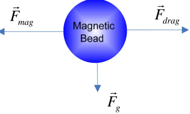
For a single magnetic bead in liquid, in addition to the magnetic force Fmag, it experiences
hydrodynamic drag force Fdrag, gravitational force and buoyancy force, while the latter two
forces can be considered as effective gravitational force F as presented in Fig.1.3, and usually g
neglected due to its small size.
mag
F
F
dragg
F
Figure 1.3 Simplified schematic diagram of the main directions of the most important forces acting on a magnetic bead.
From Maxwell tensor equation, the force on a magnetic bead due to the applied magnetic field is
F
mag= χ
V
m(
H
⋅∇
)
B
(1) whereFmagis the magnetic force on the bead, V is the volume of the bead, χ is its magnetic msusceptibility per unit volume, H is the magnetic field intensity, and B is the magnetic flux density, and “∇ ” is vector differential operator. Meanwhile, we know
B
=
μ
H
(2) where μis the permeability of the medium.In orthogonal coordinate system, extending Eq. (1) in x direction leads to
0
(
)
m x x x x x y zV
B
B
B
F
B
B
B
x
y
z
μ
χ
∂
∂
∂
=
+
+
∂
∂
∂
(3)Eq. (3) indicates that the magnetic force acting on a bead depends on the magnetic field intensity, as well as magnetic field gradient. That means a strong but uniform magnetic field may polarize or even saturate magnetic beads, but only a non-uniform magnetic field with a significant gradient will result in the movement of magnetic bead.
In addition to magnetic force, from Stokes’s law, we know the hydrodynamic force
F
drag= η
6
π
R
bead(
v
bead−
v
fluid)
(4) wherev
bead,v
fluid,R
beadandη
are the bead velocity, liquid velocity, bead radius and fluid’sviscosity, respectively. If we consider the case when beads are immobilized at the center of microcoils, when we turn off the coil, magnetic bead will be forced to move along the flow direction due to Eq. (4), at an initial velocity 0 and initial acceleration 6πηRbeadvfluid/mbead, where
bead
m is the mass of a magnetic bead. Since in most microfluidic applications, vfluidis very small,
the acceleration is also very small, which means the beads will not escape from the coil center area right away even if the magnetic force is removed in a short while.
For the manipulation of magnetic beads, the magnetic force on beads is required to be bigger than hydrodynamic drag force, and a bigger magnetic force will result in a more sensitive controlling. The magnetic field can be generated either by permanent magnets or electromagnets. The use of permanent magnets offers advantage of strong magnetic field thus large magnetic force, but it doesn’t allow flexible control of magnetic field, thus electromagnets are preferred, because the intensity and directions of magnetic field can be easily controlled the current through electromagnets.
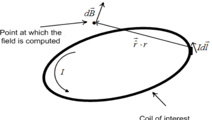
1.3 Magnetic Field Generated by Planar Microcoil
Among various electromagnets, planar microcoil is usually preferred in LoC applications, because of its low cost and compatibility with layer based microelectronic fabrication technology. A spiral microcoil of multi-turn can be considered to be composed of an equal number of concentric loops of different lengths, the total magnetic field is the sum of the magnetic field induced by each loop, and it can be obtained from the Biot-Savart’s law as shown in Fig. 1.4:
0 2 ˆ 4 Idl r B dB r μ π × =
∫
=∫
⋅ (5) where μ0is the magnetic constant; I is the current passing through wire; dl is a vector whose magnitude is the length of the differential element of the wire, and whose direction is the direction of current; ˆr is the displacement unit vector, in the direction pointing from the wire element to the point at which the field is being computed and ris the distance from the wireelement to the point at which the field is being computed.
Figure 1.4 Magnetic field generated by one loop of microcoil
Eq. (5) reveals that, approximately, for certain positions in space, the magnetic flux density generated by a coil is directly proportional to the current through the coil and inversely proportional to the distance from the investigated position to the coil. As the size of coil shrinks, it need less and less current to generate the required magnitude of magnetic field within the coil’s layout region. Hence, it can be concluded that following the minimum allowed metal width of specific fabrication process to design the coil will result in strongest magnetic field in the coil layout region.
Take the spiral microcoil as shown in Fig. 1.5 as an example: it is modeled in FEA software, with wire thickness of 1um, inner diameter of 60 µm, outer diameter of 400um, and the current passing through the coil of 100mA. FEA simulation results of the magnetic flux density versus horizontal direction and vertical direction are shown in Fig. 1.6. When the center of the coil is recognized as the origin, it is found that the magnetic flux density is almost symmetric both in x-direction and z-x-direction, and the magnitude of magnetic field drops quickly as the distance to the
coil’s centre increases, which means both the maxima of magnetic flux density and magnetic field gradient are located in the vicinity of this coil’s center.
Figure 1.5 (a)Planar spiral coil model: wire thickness 1um, inner diameter 60 µm, outer diameter 400um, and the current passing through the coil 100mA; (b) and its 3D model in FEA software and the magnetic field distribution.
Figure 1.6 Magnitude of total magnetic flux density (a) along a line parallel to the surface of the microcoil and located 20 µm above it; (b) along a line perpendicular to the surface of the microcoil and located at the center of it.
However, the above feature is not always true when the topology of microcoil varies, because the magnetic field distribution is highly geometry dependent. In a given area and consuming same current, different geometries could lead to different maximum values of magnetic field as well as their distribution. Since magnetic beads always tend to be attracted to the nearest maxima of magnetic field, the distribution of trapped magnetic beads can be estimated through investigating the geometries of planar microcoils. For example, as indicated in Fig. 1.7, coil 2&4 have their maximum magnetic field at the center with large gradient, whereas coil 1&3 don’t have their maximum magnetic field at the center but exert relatively more uniform magnetic field. In some applications, for example trapping, magnetic beads are required to be trapped on the substrate surface uniformly, instead of attracting all the magnetic beads to the center to form cluster, so the design of coil 1 or 3 to achieve a more uniform and larger trapping area is more preferred. From Fig. 1.7, it’s also found that the maximum magnetic field in coil 1&3 are lower than that in coil 2&4, therefore realizing a more uniform magnetic field is at the cost of higher current consumption as a higher current is needed to reach the same magnetic force to manipulate the magnetic beads.
Figure 1.7 Magnetic field distribution for different geometrical planar microcoils: a) planar coil models, each coil occupies an area of 450 um by 450 um, carrying a current of 30 mA; b) corresponding magnetic field distribution on the z = 1 um plane.
1.4 Joule Heat Generated by Microcoil
One inevitable but often neglected issue in electromagnet based LoC applications is Joule heat effect. The heat may damage the viability of bioparticles, because most of the bioparticles can
only keep vital in a relatively narrow temperature range. Therefore, the heat generated by microcoils has to be controllable. For a working microcoil, the induced Joule heat is
R
=
J
Q
JJ
(6) where R is the DC resistance and Jis the current density. The parabolic equation of temperature conduction is expressed [24] asˆ
( )
T
[ ( )]
q
c T
T
T
t
ρ
∂
=
− ∇
∇
∂
i
K
(7) where T is the temperature, ρ is the density, c(T) is the specific heat which might depend on the temperature, K(T) is a conductivity matrix which might be orthotropic or temperature dependant, and ˆq is the heat generation rate per unit volume.Eq. (6) and eq. (7) illustrate that a typical heating process can be recognized as two separate phases: the first is the heat generation, whereas the second is heat conduction. The topology of microcoil array influences the resistance and current density, thus affects the first process; the parameters of substrate and the medium affect the second because different materials have different specific heat and conductivities. If a DC current is applied to a microcoil, the heat generation process dominates the heating dissipation process, so the maximum temperature keeps rising. When the current is cut off, since there is no heating source any more, the heating dissipation process will dominate and the temperature of microcoil will tend to return to ambient temperature. Some previous studies used on-chip water cycling system or external thermoelectric cooler to keep temperature stable in channel, which are proved effective in holding temperature, but prior to these passive action, it is better to explore some more economic means to control Joule heat by means of novel design concept or operation scheme, which will be elaborated in Chapter 3.
1.5 Magnetic Beads Detection
In addition to using microcoil as magnetic field source to manipulate magnetic beads, the same microcoil can be used as biosensor to detect the magnetic beads. The detection of magnetic beads relies on the planar microcoil to sense the susceptibility variation caused by the presence of magnetic beads in vicinity. A microcoil is in fact an inductor, therefore, from the perspective of energy stored in the microcoil inductor,
2 2 2 0
1
1
1
2
2
2
E
LI
L I
LI
Δ =
−
= Δ
(8) where L is the inductance of microcoil and I is the current through it.Figure 1.8 Planar microcoil for monitoring magnetic susceptibility: a) the microcoil and magnetic particles with toxins captured; b) high frequency equivalent circuit model; c) cross sectional view of a microcoil showing the magnetic field distribution.
On the other hand, from the perspective of energy stored in the magnetic field which is generated by the same inductor,
' 0 2 2 0 2 2 0 0
1
1
2
2
[|
| (1
) |
| ]
2
| |
| |
2
2
P P V P VE
H Bdv
H B dv
H
H
dv
B dv
B
V
μ
χ
χ
χ
μ
μ
Δ =
⋅
−
⋅
=
+
−
=
≈
∫∫∫
∫∫∫
∫∫∫
∫∫∫
(9)where V is the volume of magnetic particles,p χis the magnetic susceptibility per unit volume
and μ0is the magnetic permeability in free space. Therefore, LΔ can be computed by equating (8) and (9) 2 2 0
| |
pB
L
V
I
χ
μ
Δ ≈
(10) From (10) we know the inductance variation of microcoil caused by magnetic beads is proportional to magnetic susceptibility χ , the magnitude of magnetic flux density B , and inversely proportional to the current I through the inductor. Noting that the above computing is under the assumption that the magnetic bead is so small that it does not affect the overall magnetic field intensity H , meanwhile B is first-order proportional to I [25] [26]. Therefore, theinductance variation of a microcoil is linear to the quantity of magnetic beads in vicinity, because a bigger quantity results in a bigger total volumeV . To achieve an accurate measurement of p
inductance variation, the microcoil can be regarded as the inductor of a LC tank, the presence of magnetic beads will increase the effective inductance, so the output frequency changes to
1/ 2 0 0 0 0 1 0 0 0 0 0
1
(1
)
2
(
)
1
(
)
(1
)
2
2
0
n nL
f
f
L
L
L C
L
L
f
f
L
L
π
− =Δ
=
=
+
+ Δ
⎛
−
⎞
Δ
Δ
⎜
⎟
≈
=
−
⎜
⎟
⎝
⎠
∑
(11)where L , 0 C and0 f are the original inductance, capacitance and oscillation frequency, 0
respectively. From (11), we know the output frequency is approximately linear to inductance variation hence linear to magnetic susceptibility according to (10). If we can measure the frequency shift in small intervals, we will get the corresponding inductance variation caused by the presence of magnetic beads, and their relationship should also be roughly linear.
In fact, although theoretically the quantity of magnetic beads is linear to the frequency shift, in practical application, some parameters need to be considered. For example, the parasitic capacitance caused by magnetic beads or bioparticles will change the oscillating frequency of the
LC tank, thus making the final frequency output nonlinear to the quantity of magnetic beads. Moreover, a good microcoil sensor needs to differentiate less magnetic beads located at stronger magnetic field region and more magnetic beads located at weaker magnetic field region, due to the non-uniformity of the magnetic field generated by microcoil. Therefore, the design of a microcoil sensor is critical. The above mentioned issues will be addressed in Chapter 4 by proposing the design of a microcoil sensor.
CHAPTER 2 STATE OF THE ART OF THE LAB-ON-CHIP
MICROSYSTEMS USING MAGNETIC BEADS
Lab-on-chip is a multidisciplinary approach used for the miniaturization, integration and automation of biological assays or procedures in analytical chemistry [27]. To realize a complete LoC microsystem, various technologies are required, such as microfluidics, microelectronic circuits, sensor technologies and packaging techniques. The microscopic handling of biological particles has gained great progress, with the development of microfluidics and microfabrication. We review in this chapter the state of the art of these technologies for bioparticles manipulation and detection using magnetic beads.
2.1 Labeled and Non-labeled Manipulation and Detection of Bioparticles---A Comparison
A variety of techniques have been reported for bioparticles manipulation and detection, and they can be classified to different types according to various classification methods, for example, according to whether bioparticles are labeled or not.
Non-labeled manipulation applies direct handling on bioparticles, exempting from the preparation of labels attach and detach. For example, mechanical micro tweezers[28] can pick and place the bioparticles in microscale for micro-surgery and tissue engineering, the manipulation is accurate and fast, but the mechanical fatigue of material limits its use. Optical manipulation, sometimes called optical tweezers, takes advantage of the forces generated by a strongly focused beam of light to trap and move objects ranging in size from tens of nanometres to tens of micrometres[29]. It can achieve high throughput manipulation but at the cost of high power consumption. Additionally, it’s very hard to integrate all the optical components, such as laser, lenses and motor, in a microsystem, which conflicts with our miniaturization target. Dielectrophoresis (DEP) can be employed to electrically manipulate the polarisable particles induced by electric field gradients[30][31], and an accurate manipulation can be achieved by applying high resolution electrodes, however, there exists some disadvantage of dielectrophoresis. Since the DEP force is proportional to the volume of the particles, which means when the size of particle decreases, higher electric field intensity is needed for generating the force to resist Brownian motion. Higher electric field intensity is from high voltage signal between electrodes, which may cause severe ionic current flow and double layer polarization effects to damage bioparticles [32][33].
Therefore, it is generally impractical to use it for objects with characteristic lengths in nanometer scale, such as DNA and some antibody-antigens [25].
Non-labeled detection of bioparticles relies on the contrast of some parameters between bioparticles and background liquid. For example, resistive biosensor measures the resistance difference between bioparticles and medium[34][35] whereas capacitive biosensor measures the capacitance difference[36][37], these biosensors are easy to be implemented, as the techniques regarding resistance and capacitance measurement are mature, however, the subtle difference between bioparticles and background liquid environment results in extremely high requirement for the sensitivity of such biosensor, which is not easy to be realized. Usually, resistive and capacitive biosensors are used in low sensitivity or large amount bioparticles detection; in order to achieve higher sensitivity bioparticles detection, optical method is employed. For example, single-photon avalanche diode (SPAD) detects the presence of bioparticles by counting the photons blocked by bioparticles[38][39], the sensitivity can be qualified for single bioparticle detection, depending on the design of SPAD. The disadvantage of this method is that an external light source needs to be installed, which is difficult to be miniaturized and integrated. A common drawback for all the above mentioned non-labeled detection techniques is that these biosensors are non-specific. Regarding the complexity of biological environment, multiple types of bioparticles usually coexist, whereas their resistances, capacitances or sizes are comparable in a short range, so it’s very difficult to differentiate them.
On the other hand, labeled bioparticles are manipulated indirectly by manipulating the labels. For example, magnetic beads as labels or carriers of bioparticles can be manipulated by magnetic field generated by permanent magnets or electromagnets. Due to the high magnetic susceptibility of magnetic beads, a very accurate and sensitive manipulation can be achieved. The labeled bioparticles detection relies on the detection of bio-labels to reflect the existence of corresponding bioparticles. For example, fluorescent labeling is a process of covalently attaching fluorophores to target bioparticles, such as protein or nucleic acid. Fluorescence-labeled bioparticles can then be detected by measuring the intensity of scattered light[40] [41] via a fluorescence microscope, flow cytometer or some other fluorescence reading instrument. It’s a widely used method in localization of a target within a cell[42], however, it also suffers from several disadvantages such as photo-bleaching, spectral overlap and additional bulky detection equipment [43][44][45][46]. These constraints have inspired the efforts of researchers to develop
the detection method using other bio-labels, for example, magnetic bead. Magnetic micro/nano particles and magnetic sensor based bioassay is called magnetic immunoassay (MIA) [47][48][49][50]. The detection of magnetic beads labeled bioparticles relies on the measurement of the magnetic susceptibility of medium in vicinity of magnetic sensor[26]. Magnetic beads as bio-labels offer a number of advantages over fluorophores labels, for example, there is no significant magnetic background present in biological environment, thus the noise interference can be minimized; magnetic beads are biocompatible and stable over time; magnetic beads as labels of bioparticles can also be manipulated by magnetic field during detection, thus various applications are possibly be achieved by configuring the local magnetic field.
2.2 Microsystems for Magnetic Beads Manipulation
Since the magnetic beads are used as carriers of various bioparticles, the mechanisms applied in the manipulation of bioparticles are actually same as the manipulation of magnetic beads. Different types of magnetic beads manipulation on microsystems, such as trapping, sorting, transporting, have been presented[51][52][53], and the most commonly used magnetic beads in those applications are ranging from 1µm to 10µm. As for the magnetic field, it can be generated by either permanent magnets or electromagnets.
A microfluidic magnetic bead separator for high-throughput applications is introduced in [54]. This microsystem consists of an array of small Nd–Fe–B permanent magnets and an array of integrated permalloy elements which are encapsulated in the bottom of a separation chamber. The permanent magnets can provide magnetic forces with a resolution of millimeter, whereas the integrated permalloy elements are employed to enhance the local forces on 10µm scale near the bottom of separation chamber. Due to the use of permanent magnets, a strong magnetic field can be generated, thus the a high efficiency of magnetic beads separation (~90%) was achieved. However, the disadvantage of using permanent magnets in microsystem is that the magnetic field distribution is fixed once the microsystem is fabricated, thus reconfigurable and flexible control of magnetic field are difficult. Meanwhile, the fabrication process to integrate permanent magnets is usually non-standard and not compatible with modern microelectronic fabrication technology. Therefore, in smart medical and biological device, planar electromagnets, which can be massive produced and integrated with microfluidic structures, are more preferred to be used as magnetic field generator.
Figure 2.2 A microsystem combining permanent magnets and electromagnets. Cu current lines are buried in the back side of the substrate at the positions indicated by the white lines.
Another hybrid magnetic bead separator demonstrated in [55] combines an external magnetic field with current lines as thick as 175 mm buried in the back side of a silicon wafer so that the magnetic beads can be activated by the uniform external strong magnetic field as well as manipulated by the on chip electromagnets. The use of electromagnets adds flexibility to this
microsystem, but the current through Cu metal is as high as 2A, which results in very high power consumption. Another drawback of applying big current lines is that due to the Joule heat generate by high current, a cooling system has to be added to avoid the overheat spots, thus the total power consumption and system complexity are further increased. These disadvantages inspire the researchers to explore how to reduce the current to generate the required magnetic field to manipulate magnetic beads. The most effective and economic way is to improve the design of electromagnets, including the geometry and topology. Fortunately, with the development of finite element analysis (FEA) software, the magnetic field generated by electromagnets can be simulated and optimized before implementing, thus more and more designs of the micro electromagnets aiming for higher manipulation efficiency have been proposed.
Figure 2.3 A summary of the performance of various planar electromagnets. Row 1: a schematic view of the microcoil; row 2: image under optical microscope; row 3: the simulated magnetic flux density profile; row 4: schematic of the magnetic bead trapping profile and; row 5: optical image of the magnetic beads trapped by corresponding microcoils [56]
Various designs of planar micro electromagnets and their FEA simulation results have been presented in [57][58][59][60][56][61]. The comparison of different geometrical configurations in Fig. 2.3 has concluded that planar spiral microcoil results in the best power efficiency, i.e. in a
given area, spiral microcoil will generate the biggest total magnetic flux density and steepest magnetic field gradient. Adding ferromagnetic pillar to the center of microcoil will further enhance the local magnetic field, but at the cost of extra fabrication steps and cost. Fig. 2.4 shows the implementation of a magnetic pillar on a silicon substrate microsystem. It’s worth noting that although spiral microcoil generates the strongest magnetic field, it is not always the best option, because in order to make a spiral microcoil, at least two metal layers are required, which is not always available for many fabrication processes. Moreover, the magnetic field distribution of a spiral magnetic field is not as uniform as other geometries, for example, serpentine, so it’s not necessarily always the best option in some magnetic beads applications. One has to consider multiple facts when designing the planar electromagnets for LoC applications.
Figure 2.4 (a) Schematic of the microsystem with the fluidic chamber on top of the coil and pillar; (b) Prototype of final fluidic device with chip inserted in. The size of the fluidic chamber is 10mm×5mm×0.1mm. The fluidic inlet and outlet, with inner diameter of 0.5 mm. The fluidic block is connected to a programmable syringe pump fitted with a 1 ml syringe[61].
In addition to generating magnetic field within a coil’s layout region, a planar microcoil is also possible to cooperate with adjacent microcoils to form a combined magnetic field. While extending the control region from single coil to coil array, more diverse functions can be achieved. Two silicon substrate based microsystems which integrate microelectronic circuits and microcoil array are introduced in [62] and [63], which aim for magnetic beads cluster manipulation and individual magnetic beads manipulation, respectively. By controlling the on and off of specific microcoil in the array, and applying corresponding control algorithm, different applications, such as trapping and transporting, can be realized. For example, in Fig. 2.5, the
transport of magnetic beads cluster is realized by an algorithm that current pulses with appropriate values and directions are alternatively applied to two neighboring microcoils. Thanks to the development of Very-Large-Scale Integration (VLSI) circuits, controlling a large scale microcoil array at a high efficiency is not a difficult task any more. All parameters regarding microcoil array controlling, such as current intensity and current direction can all be flexibly customized.
Figure 2.5 Microcoil array for magnetic beads manipulation. By controlling currents in the microcoils, many different magnetic field patterns can be generated. To generate the required fields, current pulses with appropriate values and directions are alternatively applied to two neighboring microcoils[62].
Another microsystem shown in Fig. 2.6 employs similar microcoil array and control algorithm as in [62], but for the purpose of individual magnetic beads manipulation. Individual magnetic beads manipulation follows the same mechanism as beads cluster manipulation, but usually requires higher control resolution. The manipulation resolution is highly relative to the size of microcoil and limited by fabrication process. The perfect case would be that the size of a microcoil is the same as that of a magnetic bead, thus an extremely accurate control can be achieved. Another point that is worth mentioning is that the microsystem in Fig. 2.6 exploits open cavity as microfluidic packaging, therefore it is a fast prototyping method, though not very reliable for practical use.
Figure 2.6 An open cavity microsystem integrating CMOS coil array for individual magnetic bead manipulation [51].
Although it has been demonstrated that planar microcoil based microsystem is capable of manipulate magnetic beads for different applications, such as trapping, sorting and transporting, it’s worthy of further research on the design of microcoil array, because previous research only exploited simple geometrical microcoil and controlling scheme, whereas a universal optimization method for the design of microcoil array to achieve the highest efficiency is lacked. Moreover, the inevitable overheat spot issue for electromagnets in microfluidic applications, is often ignored, thus a safe temperature range for vital bioparticles is hard to be maintained. Additionally, previous microsystems are either open cavity, for which the liquid is directly exposed to the air, or using customized processes to achieve microfluidic structures, whereas a robust microfluidic/microelectronic interface taking advantage of standard packaging technology is rarely reported. Therefore, the above presented microsystems are mostly confined in laboratory. These constraints are addressed in Chapter 3 and Chapter 5 of this thesis work and resolved by our proposed microsystems.
2.3 Microsystems for Magnetic Beads Detection
Accurate and effective detection of bioparticles in microfluidic is always a challenging work, as several criteria need to be respected simultaneously, including repeatability, accuracy, stability, cost and most importantly, the viability of bioparticles. In magnetic beads applications, the detection of bioparticles is represented by the detection of magnetic beads, because the bioparticles are attached to the magnetic beads. The main advantage is that a high signal to noise (SNR) ratio can be achieved, since magnetic beads as labels of bioparticles show strong contrast to non-magnetic background biological environment. To detect the bioparticles attached magnetic beads, various biosensors have been reported, including Hall sensor, Giant Magnetoresistance (GMR) sensor, Nuclear Magnetic Resonance(NMR) sensor, and inductance sensor[64][43]. In this chapter, we summarize all these techniques with emphasis on inductance measurement based sensor, as this sensor uses the low cost coil as inductor and the fabrication process is compatible with regular integrated circuits thus it provides significant cost advantage over others. Additionally, planar microcoil based inductance sensor can take advantage of the manipulation capability of the same coil, thus a multifunctional LoC microsystem can be achieved on the same substrate.
2.3.1 GMR Sensor
GMR is a quantum mechanical magnetoresistance effect observed in thin film structures composed of alternating ferromagnetic and non magnetic layers[65]. The 2007 Nobel Prize in physics was awarded to Albert Fert and Peter Grünberg for the discovery of GMR. Depending on whether the magnetizations of adjacent ferromagnetic layers are in parallel or anti-parallel alignment, a significant change in the electrical resistance can be observed. The total resistance is relatively low for parallel alignment of adjacent layers and relatively high for anti-parallel alignment.
Recently, GMR has been drawing attention for the application in biochip. For example, Figure 2.7 shows a proposed integrated silicon substrate based GMR sensor for magnetic particles detection [54]. It includes four spin-valve GMRs wired as Wheatstone bridges. In each bridge, two GMRs act as sensing resistors and are located under a microfluidic channel. The other two GMRs serve as reference resistors, which are located beneath the insulation layer and separated from the edge of the neighboring sensing GMRs. As the magnetic particles approach the sensing
![Figure 1.1 Diagram of (a) a red blood cell, (b) a magnetotactic bacterium, (c) a cell with digested magnetic nanoparticles, and (d) a cell with magnetic micro/nano particles attached to the surface [9]](https://thumb-eu.123doks.com/thumbv2/123doknet/2352857.36654/25.892.127.767.447.754/magnetotactic-bacterium-digested-magnetic-nanoparticles-magnetic-particles-attached.webp)

![Figure 2.6 An open cavity microsystem integrating CMOS coil array for individual magnetic bead manipulation [51]](https://thumb-eu.123doks.com/thumbv2/123doknet/2352857.36654/44.892.229.664.155.579/figure-cavity-microsystem-integrating-cmos-individual-magnetic-manipulation.webp)
![Figure 2.8 A conceptual schematic view of a Hall sensor for single magnetic particle detection[69]](https://thumb-eu.123doks.com/thumbv2/123doknet/2352857.36654/48.892.250.638.138.699/figure-conceptual-schematic-sensor-single-magnetic-particle-detection.webp)
![Figure 2.10 A microsystem for CMOS frequency-shift-based magnetic sensor array with integrated microfluidic structures (left) and the zoom-in view of one differential sensing pair (right) [59]](https://thumb-eu.123doks.com/thumbv2/123doknet/2352857.36654/51.892.141.750.509.852/microsystem-frequency-magnetic-integrated-microfluidic-structures-differential-sensing.webp)
![Figure 2.13 Fabrication procedure of DWFP technique: (a) ink deposition, (b) encapsulation in epoxy and (c) ink extraction [81]](https://thumb-eu.123doks.com/thumbv2/123doknet/2352857.36654/55.892.171.726.143.394/figure-fabrication-procedure-dwfp-technique-deposition-encapsulation-extraction.webp)