PERFORMANCE EVALUATION AND ANALYSIS OF MIMO SCHEMES IN LTE NETWORKS ENVIRONMENT
ALI JEMMALI
D´EPARTEMENT DE G´ENIE ´ELECTRIQUE ´
ECOLE POLYTECHNIQUE DE MONTR´EAL
TH`ESE PR´ESENT´EE EN VUE DE L’OBTENTION DU DIPL ˆOME DE PHILOSOPHIÆ DOCTOR
(G´ENIE ´ELECTRIQUE) D´ECEMBRE 2013
c
´
ECOLE POLYTECHNIQUE DE MONTR´EAL
Cette th`ese intitul´ee :
PERFORMANCE EVALUATION AND ANALYSIS OF MIMO SCHEMES IN LTE NETWORKS ENVIRONMENT
pr´esent´ee par : JEMMALI Ali
en vue de l’obtention du diplˆome de : Philosophiæ Doctor a ´et´e dˆument accept´ee par le jury d’examen constitu´e de :
M. CARDINAL Christian, Ph.D., pr´esident
M. CONAN Jean, Ph.D., membre et directeur de recherche M. WU Ke, Ph.D., membre et codirecteur de recherche M. AKYEL Cevdet, D.Sc.A, membre
To my dear mother, my dear wife and dear son, In memory of my father. . .
ACKNOWLEDGEMENTS
I would like to express the deepest appreciation to my director of research, Dr Jean Co-nan and my co-director of research, Dr Ke Wu. My sincere gratitude goes to my director of research for his continuous support of my Ph.D study and research, for his motivation, enthusiasm and immense knowledge. His guidance helped me in all the time of research and writing of this thesis. I also wish to express my truthful recognition to Dr Ke Wu for his continuous encouragement and support. Without the support, encouragement of my super-visors, this thesis would not have been possible.
My sincere gratitude goes towards my thesis examiners :
– Prof. Cardinal Christian (Committee Chair), Dept. Electrical Engineering, ´Ecole Poly-technique, Montr´eal,
– Prof. Ajib Wessam (External Examiner), Dept. Computer Science, UQAM, Montr´eal, – Prof. Cevdet Akyel, Dept. Electrical Engineering, ´Ecole Polytechnique, Montr´eal, for accepting reviewing my work and for their valuable comments towards the impro-vement of my final thesis report, as well as putting me through a stimulating, albeit a bit stressful, defense experience.
Special thanks go also go to my student colleagues in the laboratory for the technical exchanges and fruitful discussions. I mention for memory Wael, Jihed and Tarek. My truth-ful recognition goes to Mohammad Torabi for his precious help and advises. Big thanks also goes to my colleagues, namely Vladan Jevromovic and Benoit Courchesne for their encourage-ment and for giving me one day off for more than one year to help me finalize my thesis work.
Last but not least, I would like to thank my dear wife for her patience, support and sacrifice.
R´ESUM´E
Dans cette th`ese, nous proposons d’´evaluer et d’analyser les performances des configu-rations radio `a antennes multiples `a l’´emission et/ou la r´eception (MIMO) dans l’environ-nement des r´eseaux LTE (Long Term Evolution). Plus sp´ecifiquement, on s’int´eresse `a la couche physique de l’interface radio OFDM-MIMO de ces r´eseaux. Apr`es une introduction rapide aux r´eseaux LTE et aux techniques MIMO, on pr´esente dans une premi`ere ´etape, une analyse th´eorique du taux d’erreur binaire en fonction du rapport signal sur bruit des deux principaux codes spatio-temporels de la norme LTE, `a savoir le codage SFBC 2× 1 (Space Frequency Block Coding) et le codage FSTD 4× 2 (Frequency Switch Transmit Diversity). On d´eveloppe les ´equations analytiques du taux d’erreur binaire de ces codes dans un canal `a ´evanouissement de Rayleigh sans corr´elation spatiale qui sont par la suite compar´ees `a des valeurs obtenues par simulations Monte-Carlo. Dans une deuxi`eme ´etape, on consid`ere l’´eva-luation de la capacit´e du canal r´esultant de l’utilisation de ces mˆemes codes dans un canal `a ´evanouissement de Rayleigh. Pour fin de comparaison, on propose par la suite d’´evaluer par simulation leur d´ebit effectif. Les r´esultats montrent que la capacit´e peut effectivement ˆetre presque atteinte en pratique. Le deuxi`eme volet de cette th`ese consid`ere les performances des syst`emes MIMO utilisant la s´election d’antennes. Nous utilisons la th´eorie d’ordre statistique pour d´evelopper des ´equations analytiques relatives au taux d’erreur binaire des syst`emes avec s´election d’antennes du cot´e r´ecepteur dans un canal d’´evanouissement de Rayleigh sans corr´elation spatiale. Afin de valider num´eriquement les r´esultats de notre analyse, un algo-rithme `a s´election d’antenne au r´ecepteur a ´et´e d´evelopp´e et utilis´e en simulation. Dans un dernier temps, on ´evalue l’effet de la corr´elation spatiale entre les antennes. L’´etude est faite `a partir de simulations et d’un mod`ele de corr´elation spatiale bas´e sur le produit Kronecker de deux matrices de corr´elation relatives respectivement `a l’´emission et `a la r´eception.
ABSTRACT
This thesis considers both an analysis and a numerical evaluation of the performance of MIMO radio systems in the LTE network environment. More specifically we consider the physical layer of the OFDM-MIMO based radio interface. As a first step we present a theo-retical analysis of the bit error rate of the two space-time codes adopted by the LTE norm, namely the SFBC 2× 1 and FSTD 4 × 2 codes, as a function of the signal upon noise ratio. Analytical expressions are given for transmission over a Rayleigh channel without spatial correlation which are then compared with Monte-Carlo simulations. As a second step, we consider the capacity of the channel obtained by using these codes on a Rayleigh fading channel. Results show that simulated throughput almost reaches the capacity limit. As a different topic, this thesis considers also MIMO systems based on antenna selection. By us-ing order statistics we develop analytical expressions for the error rate on a Rayleigh channel without antenna correlation. In order to validate our numerical results, an algorithm imple-menting antenna selection at the receiver has been developed and used in the simulations. As a last step the effect of antenna correlation is investigated through the use of simulations and a model of spatial antenna correlation based on the Kronecker product of two correlation matrices related to the transmitting and receiving elements of the MIMO scheme.
TABLE OF CONTENTS
DEDICACE . . . iii
ACKNOWLEDGEMENTS . . . iv
R´ESUM´E . . . v
ABSTRACT . . . vi
TABLE OF CONTENTS . . . vii
LIST OF TABLES . . . ix
LIST OF FIGURES . . . x
LIST OF APPENDICES . . . xii
LIST OF ACRONYMS . . . xiii
CHAPTER 1 INTRODUCTION . . . 1
1.1 Introduction . . . 1
1.2 Motivation . . . 2
1.3 Research Objective and Contributions . . . 3
1.4 Dissertation Outline . . . 4
CHAPTER 2 TECHNICAL OVERVIEW OF LTE SYSTEMS . . . 5
2.1 LTE System Architecture . . . 5
2.1.1 Core Network . . . 6
2.1.2 The Access Network . . . 6
2.2 LTE Physical Layer . . . 8
2.3 LTE Frame Structure . . . 10
2.4 MIMO-OFDM Schemes in LTE . . . 17
2.4.1 Array Gain . . . 18
2.4.2 Diversity Gain . . . 18
2.4.3 Multiplexing Gain . . . 19
2.4.4 Diversity Schemes in LTE . . . 21
CHAPTER 3 PERFORMANCE EVALUATION OF MIMO SYSTEMS IN LTE . . . 28
3.1 Introduction . . . 28
3.2 BER Analysis of LTE MIMO Schemes . . . 30
3.2.1 System Model . . . 30
3.2.2 Average BER Performance analysis for several M-QAM Schemes . . . . 30
3.2.3 Numerical results and discussions for the average BER . . . 34
3.3 Channel Capacity Analysis for LTE systems . . . 37
3.3.1 Channel Model and Channel Capacity of Spatial Multiplexing Scheme . 38 3.3.2 Channel Model and Channel Capacity of Diversity Schemes . . . 39
3.4 Data Throughput Performance Evaluation for M-QAM Modulation Schemes . 44 3.4.1 Numerical Results and Discussion for System Throughput . . . 47
CHAPTER 4 ANTENNA SELECTION IN MIMO SYSTEMS . . . 52
4.1 Antenna Selection Overview . . . 53
4.1.1 Antenna Selection Scheme based on the Channel Capacity . . . 56
4.1.2 Antenna Selection Scheme based on the SNR . . . 58
4.1.3 Antenna Selection Algorithms . . . 59
4.2 Performance Evaluation of UCBS Antenna Selection Algorithm . . . 68
4.2.1 Impact of the UCBS Algorithm on the capacity of MIMO systems . . . 68
4.3 BER Analysis of the MIMO STBC System using Receive Antenna Selection . 70 4.3.1 Error analysis of the receive antenna selection scheme . . . 71
4.4 Effect of Antenna Correlation on Receive Antenna Selection . . . 75
4.4.1 System and Channel Model . . . 76
4.4.2 Simulations Results and Discussion . . . 77
CHAPTER 5 SUMMARY AND CONCLUSIONS . . . 83
5.1 Future Work . . . 84
5.1.1 MU-MIMO Aspects . . . 84
5.1.2 CSI Aspects . . . 84
5.1.3 Frequency Selective Channel Aspects . . . 85
5.1.4 Antenna Correlated Channel Aspects . . . 85
5.1.5 Contributions and Publications . . . 85
REFERENCES . . . 87
LIST OF TABLES
Table 2.1 Resource Block as a function of Channel Bandwidth . . . 15
Table 2.2 Antenna ports and their associated Reference Signals . . . 20
Table 2.3 Codewords-to-layer Mapping in LTE . . . 24
Table 2.4 Codewords for 2× 2 Open Loop Spatial Multiplexing . . . 25
Table 2.5 Codewords for 4× 4 Open Loop Spatial Multiplexing . . . 25
Table 3.1 Simulation Settings . . . 35
Table 3.2 Number of Resource Blocks . . . 45
Table 3.3 ECR and Modulation Order for CQI . . . 46
Table 3.4 SISO Generated Data . . . 47
LIST OF FIGURES
Figure 2.1 LTE System Architecture. . . 5
Figure 2.2 User Plan Protocols. . . 8
Figure 2.3 Control Plan Protocols. . . 8
Figure 2.4 LTE downlink Physical Layer Block Diagram. . . 9
Figure 2.5 Type 1 LTE FDD Frame Structure. . . 11
Figure 2.6 Type 2 LTE TDD Frame Structure. . . 11
Figure 2.7 Structure of the symbols in one slot with Normal Cyclic Prefix. . . 12
Figure 2.8 Structure of the symbols in one slot with Extended Cyclic Prefix. . . . 13
Figure 2.9 OFDM Signal Generation. . . 14
Figure 2.10 LTE Resource Block. . . 15
Figure 2.11 Physical Channels and Physical Signals in LTE. . . 16
Figure 2.12 Space Frequency Block Coding (SFBC) Scheme in LTE . . . 21
Figure 2.13 Frequency Switched Transmit Diversity (FSTD) Scheme in LTE . . . . 22
Figure 2.14 2× 2 Open Loop Spatial Multiplexing with Large-Delay CDD Precoding. 26 Figure 3.1 BER Results for QPSK Modulation . . . 36
Figure 3.2 BER Results for 16-QAM Modulation . . . 36
Figure 3.3 BER Results for 64-QAM Modulation . . . 37
Figure 3.4 Capacity for SISO, SFBC-OFDM and FSTD-OFDM Schemes . . . 43
Figure 3.5 System Capacity as a function of SNR . . . 46
Figure 3.6 Data Throughput for QPSK Modulation . . . 48
Figure 3.7 Data Throughput for 16QAM Modulation . . . 49
Figure 3.8 Data Throughput for 64QAM Modulation . . . 50
Figure 3.9 Coded Data Throughput for M-QAM Modulation . . . 51
Figure 4.1 MIMO system Model with Antenna Selection . . . 55
Figure 4.2 MIMO Capacity with Antennas Selection . . . 69
Figure 4.3 Comparison of Simulation Results and Analytical expressions . . . 75
Figure 4.4 Receive Antenna Selection With mixed Correlation (Lr= 2; Nr = 3) . . 78
Figure 4.5 Receive Antenna Selection With mixed Correlation (Lr= 2; Nr = 4) . . 79
Figure 4.6 Receive Antenna Selection With mixed Correlation (Lr= 2; Nr = 6) . . 80
Figure 4.7 Receive Antenna Selection With mixed Correlation (Lr= 2; Nr = 8) . . 81
Figure 4.8 BER of Receive Antenna Selection with mixed Correlation (ρ = 0.9) . . 82
Figure A.1 BER of Receive Antenna Selection with receive antenna Correlation . . 92
Figure A.3 BER of Receive Antenna Selection (ρtx= 0 and Nr = 4) . . . 94 Figure A.4 BER of Receive Antenna Selection (ρtx= 0 and Nr = 6) . . . 95 Figure A.5 BER of Receive Antenna Selection (ρtx= 0 and Nr = 8) . . . 96 Figure D.1 Functional Block Diagram of Vienna LTE Link Level Simulator . . . . 102 Figure D.2 Functional Block Diagram of the Transmitter of the LTE Simulator . . 103 Figure D.3 Functional Block Diagram of the Receiver of the LTE Simulator . . . . 105
LIST OF APPENDICES
Appendice A IMPACT OF RECEIVE ANTENNA CORRELATION . . . 92 Appendice B DERIVATION OF THE ALTERNATIVE FORM OF Q-FUNCTION . 97 Appendice C BER EVALUATION USING THE ALTERNATIVE Q-FUNCTION . . 100 Appendice D VIENNA LTE LINK LEVEL SIMULATOR . . . 102
LIST OF ACRONYMS
MIMO Multi-Input Multi-Output SIMO Single-Input Multi-Output MISO Multi-Input Single-Output LTE Long Term Evolution
SAE System Architecture Evolution
OFDM Orthogonal Frequency Division Multiplex
OFDMA Orthogonal Frequency Division Multiplex Access IFFT Inverse Fast Fourier Transform
FFT Fast Fourier Transform BER Bit Error Rate
SNR Signal to Noise Ratio
MGF Moment Generating Function PDF Probability Density Function CDF Cumulative Distribution Function EPC Evolved Packet Core
E-UTRAN Evolved Universal Terrestrial Radio Access Network
DL Uplink Channel
UL Downlink Channel
CRC Cyclic Redundancy Check MAC Medium Access Control RLC Radio Link Control RRC Radio Resource Control
CW Code Word
RE Resource Element
RB Resource Block
FDD Frequency Division Duplex TDD Time Division Duplex TTI Transmission Time Interval CP Cyclic Prefic
UpPTS Uplink Pilot Time Slot DwPTS Downlink Pilot Time Slot NRB
DL Number of RB in the Downlink Link PSS Primary Synchronization Signal
SSS Secondary Synchronization Signal PBCH Physical Broadcast Channel
PCFICH Physical Control Format Indicator Channel PHICH Physical Hybrid ARQ Indicator Channel PDCCH Physical Downlink Control Channel PDSCH Physical Downlink Shared Channel PMCH Physical Multicast Channel
MRC Maximum Ratio Combining AWGN Additive White Gaussian Noise STBC Space Time Block Coding SFBC Space Frequency Block Coding Nt Number of Transmit Antennas Nr Number of Receive Antennas
γ Instantaneous Signal to Noise Ratio
γi Instantaneous Signal to Noise Ratio at ith Branch γc Instantaneous Combined Signal to Noise Ratio γ Average Signal to Noise Ratio
Nd Diversity Order
CSI Channel State Information
CSIT Channel State Information at the Transmitter
UE User Equipment
TB Transport Block
FSTD Frequency Switched Transmit Diversity CQI Channel Quality Indicator
HARQ Hybrid Automatic Repeat reQuest MMSE Minimum Mean Square Error SIC Successive Interference Cancelation RI Rank Indicator
CDD Cyclic Delay Diversity
3GPP 3rd Generation Partnership Project RS Reference Signal
ℜ{x} Real Part of x ℑ{x} Imaginary Part of x LLS Link Level Simulator PMI Precoding Matrix Indicator
CHAPTER 1
INTRODUCTION
1.1 Introduction
To increase the capacity and speed of wireless communication systems, a new type of wireless data networks has recently emerged and been standardized by the 3rd Generation Partnership Project (3GPP). This new standard comes as a natural evolution to the existing second (2G) and third (3G) generation wireless networks in order to respond to the growing demand in terms of extended data rates and speed and is marketed as the 4G Long Term Evolution (LTE) network. It was first proposed by NTT DoCoMo of Japan in 2004, and studies on the new standard officially commenced in 2005. In may 2007, the LTE and the System Architecture Evolution (SAE) Trial Initiative (LSTI) was founded as a global collaboration between vendors and operators with the goal of verifying and promoting the new standard in order to ensure as quickly as possible the global introduction of the new technology. The LTE standard was finalized in December 2008, and the first publicly available LTE service was launched by TeliaSonera in Oslo and Stockholm on December 2009 as a data connection with a Universal Serial Bus (USB) modem. By the end of 2012 already 113 commercial LTE networks in 51 countries have been deployed and the Global mobile Suppliers Association (GSA) forecasts, by the end of 2013, that the number of deployed commercial LTE networks will reach 209 in 75 countries. In Canada, Rogers Wireless was the first wireless network operator to launch LTE network on July, 2011 offering the Sierra Wireless AirCard USB mobile broadband modem known as the LTE Rocket stick. Initially, CDMA operators planned to upgrade to rival standards called Ultra Mobile Broadband (UMB) and WiMAX, but finally all the major CDMA operators in the world have announced that they intended to migrate to LTE after all. The most recent evolution of LTE has been standardized in March 2011 and is known as LTE-Advanced. The LTE-Advanced services are expected to begin in 2013. Comparing with other standards, the key aim of UMTS and GPRS/EDGE was the expansion of service provision beyond voice calls towards a multi service air interface. This objective was achieved by circuit switching and packet switching. In contrast to the former technology family of standards, LTE was designed from the start with the goal of evolving the the radio access technology under the assumption that all services would be packet switched, rather than following the circuit switching model of earlier systems.
1.2 Motivation
The third generation (3G) wireless communication systems, mainly based on the WCDMA technology, have been confronted with a number of new challenges regarding to the design of the required wireless communication systems. The main challenges the 3G technology has been facing can be summarized as follows:
– The data rate of the 3G system needs to be increased by introducing new techniques such as HSPA and HSPA+. Since the 3G is based on WCDMA technology in a 5 MHz bandwidth, the data rate couldn’t be improved as much as planned.
– The typical delay spread observed in wireless channel puts a strong limitation on the symbol duration period if it is transmitted serially. To struggle with the time delay spread of the wireless channel, the delay spread should be smaller than the symbol period, which is not the case for high data rate serial transmission, where, in general, the delay spread is much bigger than the transmitted symbol period. It is well known that the delay spread of the channel causes Inter Symbol Interference (ISI) which can be undone often only partially by means of complex equalization procedures. In WCDMA, since the signal is transmitted serially in time it is highly challenging to increase the data rate of the transmitted signal.
To contend with the above mentioned challenges and to achieve good system performance, the choice of an appropriate modulation and multiple access schemes applicable to mobile wireless communication systems is then critical. In this context, the parallel multi carriers schemes have shown their efficiency in many wireless applications. More specifically, the Or-thogonal Frequency Division Multiplexing (OFDM) which is a special case of multi carrier transmission is a good choice. In OFDM, the frequency selective fading wide band channel is used as frequency multiplex of non frequency selective (flat fading) narrow band paral-lel sub channels. To avoid the need to separate the carriers by means of guard-bands and therefore make OFDM highly spectrally efficient, the sub channels in OFDM are overlapping and orthogonal. Initially, only analog design was considered, using banks of sinusoidal signal generators and demodulators to process the signal for multiple sub channels. The tremen-dous advancement in digital signal processing made the implementation of digitally designed OFDM possible and cost effective using the Discrete Fast Fourier Transform (DFFT). The OFDM became the modulation of choice for many applications for both wired systems (such us Asymmetric Digital Subscriber Line (ADSL)) and wireless broadcasting systems such as Digital Audio Broadcasting (DAB) and Digital Video Broadcasting (DVB) as well as Wireless
Local Area Network (WLAN). In addition to the mentioned benefits of OFDM technology, this multi carrier modulation has the ability to be adapted in a straightforward manner to operate in different channel bandwidth according to spectrum availability. All above men-tioned benefits have strongly motivated the choice of OFDM in the LTE system. Beside the OFDM schemes, the use of multi antenna techniques always been known to be of value in improving the performance of general wireless communication systems including early line of sight systems. Nevertheless, most of the theoretical development in understanding their fundamental benefits has appeared only in the last 15 years, driven by advancement in signal processing and Shannon’s information theory. A key innovation being accomplished with the introduction of the concept of so-called Multiple Input Multiple Output (MIMO) systems in the mid-1990s. In fact, serious attention to the utilization of multiple antenna techniques in mass market commercial wireless networks has only been granted since around 2000. The key role that MIMO technology plays in the latest wireless communication standards for personal area networks testifies to its importance. The MIMO technique was adopted for the first time in the release 7 version of HSDPA (High Speed Downlink Packet Access) and LTE is the first wireless communication system to be developed with MIMO as a key component form the start. In chapter 2, we will provide the necessary theoretical background for a good understanding of the role and advantage promised by MIMO techniques in general wireless communication.
1.3 Research Objective and Contributions
Nowadays, the performance evaluation of LTE systems is mainly obtained through rather time consuming simulators and it is extremely difficult to evaluate the influence of the different parameters. The objective of this dissertation is to derive analytical models that will partially compensate for these drawbacks. More specifically, we focus on the link level performance of the physical layer. Three main key performance indicators are considered in this study, namely the Bit Error Rate (BER), Channel Capacity as well as the data throughput, all in terms of Signal to Noise Ratio (SNR). We also consider to analyze and evaluate MIMO systems using antenna selection techniques. In a first step, we analyze the BER performance of MIMO system when antenna selection is applied at the receiver side. In a second step, we evaluate the impact of antenna correlation on the BER performance of MIMO systems using receive antenna selection. A subject rarely considered in the current literature.
1.4 Dissertation Outline
In this work we provide several analytical performance analysis of MIMO schemes defined in the 4G LTE standard as well as comparison with simulations results which we believe are significant contributions. The document pertaining to this thesis is organized as follows:
– In Chapter 2, we present a technical overview of LTE systems. More specifically, the system architecture of LTE is highlighted and explained. Since our study concentrates on the physical layer of LTE systems, we emphasize particularly the OFDMA and MIMO schemes used by the LTE systems. The overall frame structure of the LTE signal is also considered with some depth.
– The main performance analysis of different MIMO scheme scenarios in LTE are given in Chapter 3. At first, we describe the system model used for the analysis. Then, the detailed Bit Error Rate analysis with mathematical derivation for different modulation order and different MIMO arrangements are developed. The approach used for this analysis is based on the Probability Density Function (PDF) of the instantaneous Signal to Noise Ratio (SNR) and the Moment Generating Function (MGF) approach. The channel capacity as well as data throughput are also derived in this chapter. To validate the accuracy of our analysis, simulation results of the analysed schemes are shown and compared to the analytical results.
– In Chapter 4, the principles and performance analysis of the Antenna selection algo-rithm of MIMO Systems are presented. After a brief introduction, the system model used for our analysis is given. A subsection dedicated to the BER performance analysis for receive antenna selection follows the introduction. The theory of order statistics used for this analysis is also introduced in this section. To validate the analytical re-sults, the simulations results of antenna selection algorithm are shown and compared to the numerical results. In the second part of this chapter, the impact of antenna correlation on the performance of MIMO systems using antenna selection is evaluated. The system model used for this evaluation is also shown in this section.
– The summary and conclusion of this dissertation are made in Chapter 5, where we outline the basic contributions of the overall work and present an outline of possible future extensions.
CHAPTER 2
TECHNICAL OVERVIEW OF LTE SYSTEMS
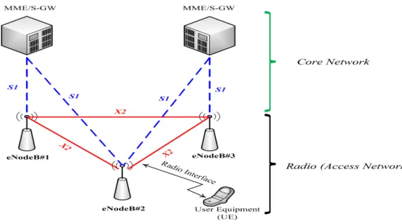
In this chapter, a brief technical overview of the LTE systems is provided. We start by a brief description of the high level overall LTE system architecture, which consists of two parts; namely the radio and core network parts as shown in Figure 2.1. Since our main work in this thesis is related to the performance of the LTE physical layer, we will detail, more specifically, the physical layer of the radio part of LTE system. Due to its significant importance and relevance in our analysis and evaluation, one section is dedicated to the frame structure of the physical layer in which we explain how the data is organized in the time and frequency domains as well as how the data is transmitted over the air. Finally, we conclude the chapter by presenting the MIMO-OFDM schemes as defined in LTE which are relevant to our study.
2.1 LTE System Architecture
Figure 2.1 LTE System Architecture.
To understand the general structure of 4G (also called Evolved 3G) wireless commu-nications systems, it is primordial to know its overall network architecture as well as the
functionalities of each element. As any other wireless communications network, the 4G sys-tem consists of two main parts, namely the core network part and the radio part. The core side of the network is called System Architecture Evolution (SAE) and the radio part is known as Long Term Evolution (LTE). The term LTE encompasses the Evolved Universal Terrestrial Radio Access Network (E-UTRAN) and represents the radio access network. The description of each part will be presented separately in the following subsections.
2.1.1 Core Network
At the beginning of the standardization process, the core network of the Evolved 3G network was designated by SAE but nowadays the core network is also called Evolved Packet Core (EPC) and the term SAE is used in parallel with EPC. The main functionality of the EPC is to provide access to external packet networks based on Internet Protocol (IP) and performs a number of functions for idle and active terminals. The whole functionalities of the core network (EPC) are performed using the following main logical nodes:
– Packet Data Network (PDN) Gateway (P-GW) – Serving Gateway (S-GW)
– Mobility Management Entity (MME)
The main functionality of P-GW is to allocate IP addresses for the user equipment (UE). It is responsible for the filtering of downlink user’s IP packets into the different radio ser-vices. Serving Gateway acts as the local mobility anchor for the data transmission when user equipment moves between eNodeBs. A mobile anchor means that the data for a specific user equipment pass through the S-GW regardless of the serving eNodeB to which the mobile is connected. The main functionality of the Mobility Management Entity is to process the signaling between the user equipment and the core network.
2.1.2 The Access Network
The access network of LTE, i.e., E-UTRAN, consists of a network of base stations called eNodeBs, as illustrated in Figure 2.1 above. In this Figure, a user equipment (UE) is con-nected to eNodeB#2 using the radio interface. The elements of the core network; namely the MME and S-GW as described in the previous section are also shown in this Figure. The eN-odeBs are connected to the core network (EPC) via S1 interfaces. Two types of S1 interfaces are standardized in LTE. The S1-U, referred to as S1 User plan interface and S1-C, referred to as S1 Control plan interface. The communications between eNodeBs is also possible in LTE and it is assured by the so called X2 interfaces which enable a meshed radio access
network (RAN) architecture. The E-UTRAN is responsible of all functions related to the radio interface and its main function can be summarized briefly as follows:
– Connectivity to the EPC : This function handles the radio communications between the mobile user and the EPC network.
– Radio Resource Management (RRM)- This covers all functions related to the radio bearers such as radio bearer control, radio admission control, radio mobility control, scheduling and dynamic allocation of resources to UE in both uplink and downlink. Radio bearer can be defined as a pipeline connecting two or more points in the com-munication system in which data traffic follow through.
– Header compression: This function helps to provide efficient use of the radio interface by compressing the IP packet headers that could otherwise cause a significant overhead, especially for small packets such as voice over IP.
– Security: All data sent over the radio interface is encrypted.
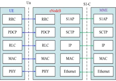
In LTE, the radio interface, also called Uu interface, protocols that run between eNodeBs and an UE are divided into two plans, namely the user plan and the control plan. The control plan protocols are responsible for managing the control signaling whereas the user plan is responsible for transporting user traffic data. In Figure 2.2, the protocol stacks of the user plan are shown, where PDCP (Packet Data Convergence Protocol), RLC (Radio Link Control), MAC (Medium Access Control) and PHY (Physical) sublayers perform functions, such as header compression, retransmissions during handover, segmentation and reassembly of upper layers packets, scheduling and multiplexing data from different control channels. To be complete, the protocol stacks of the interface between the eNodeB and the serving GW, called S1-U interface, is also shown in Figure 2.2.
The protocols stacks of the control plan appear in Figure 2.3. It can be seen from the figure that the control plan protocols differ only by the so-called Radio Resource Control (RRC) sublayer with respect to the user plan protocols. In fact, all other sublayers perform the same functions as in the user plan. For the control plan, the eNodeB interfaces with the MME entity and the interface between them are designated by S1-MME as shown in Figure 2.3.
The above is just an outline of the actual architecture of the LTE concept. Since our main work in this thesis is related to the LTE physical layer aspects, more details about the LTE physical layer will be presented in the forthcoming sections.
Figure 2.2 User Plan Protocols.
Figure 2.3 Control Plan Protocols.
2.2 LTE Physical Layer
The role of the physical layer in LTE is mainly to transform the base-band data into a reliable signal for transmissions across the radio interface between the eNodeB and the User Equipment (UE) in both directions, i.e., from eNodeB to UE, (Downlink Channel (DL)), and from UE to eNodeB, (Uplink Channel (UL)). The simplified block diagram of the LTE downlink physical layer is shown in Figure 2.4.
Each block of data, received from the upper layer (MAC layer) (See Figures 2.2 and 2.3) is first protected against transmission errors, usually first with Cyclic Redundancy Check (CRC). Then using Turbo codes, the block of data is coded to form a codeword (CW). After
Figure 2.4 LTE downlink Physical Layer Block Diagram.
channel coding, an initial step of scrambling is applied to the physical channel, and serves the purpose of interference rejection. The scrambling task is performed using an order 31 Gold code, that can provide 231 sequences with no cyclic shifts. The attractive feature of Gold codes is that they can be generated with very low implementation complexity, as they can be derived from the modulo-2 addition of two maximum length sequences, which can be generated by a simple shift register. Following the scrambling operation, the transmitted data bits are mapped into modulated complex value symbols depending on the modulation scheme which is used. After modulation task, a layer mapping is applied to the modulated codewords (CW). In LTE, a layer mapper maps the modulated symbols belonging to either 1 or 2 codewords into a number of layers less or equal to the number of antennas ports. In LTE, antenna port is a new term used to differentiate with the physical antenna. Usually, antenna ports map into physical antenna elements. A more formal definition of antenna port will be given later in this chapter. An operation of precoding follows the layer mapping, which consists of applying coding to the layers of modulated symbols prior to mapping onto Resource Element (RE). The concept of Resource Element will be explained later in section 2.3. The final stage of the LTE block diagram is the transformation of the complex modulated symbols at the output of RE mapper into a complex valued OFDM signal by means of an Inverse Fast Fourier Transform (IFFT).
As indicated in Figure 2.4, the LTE downlink transmission is based on Orthogonal Fre-quency Division Multiplexing Access (OFDMA). OFDMA is known as a technique of encod-ing digital data on multiple carrier frequencies. The principle of OFDMA is to convert a wide band frequency-selective channel into a set of many flat-fading subchannels using op-timum receivers that can be implemented with a reasonable system complexity, in contrast
to WCDMA systems. Another important advantage of OFDMA is the easy frequency do-main scheduling, typically by assigning only good channels (i.e., channels with high SNRs) to the users. It is well known that OFDMA is an efficient technique to improve the spectral efficiency of wireless systems [38]. By converting the wide-band frequency-selective channel into a set of several flat fading sub-channels, OFDM becomes more resistant to frequency selective fading than single carrier systems. Since OFDM signals are in time and frequency domains, in addition to the use of time domain scheduling, a frequency domain scheduling can also be used. The role of the user scheduler at the transmitter side is to assign the data rate for each user according to the channel conditions from the serving cell, the interference level from other cells, and the noise level at the receiver side. It has been proven [43] that in LTE, for a given transmission power, the system data throughput and the coverage area can be optimized by employing Adaptive Modulation and Coding (AMC) techniques.
2.3 LTE Frame Structure
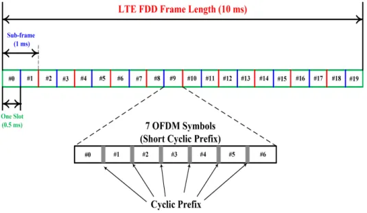
Two types of LTE frame structures are defined depending on the duplexing mode of the transmission. Two duplexing methods are defined in LTE, namely Time Division Duplex (TDD) and Frequency Division Duplex (FDD). In the FDD mode, the downlink path (DL), from the eNodeB to UE, and the uplink path (UL), from the UE to eNodeB, operate on dif-ferent carrier frequencies. In the TDD mode, the downlink and the uplink paths operate on the same carrier frequency but in different time slots. In other word, in FDD, the downlink and uplink transmissions are separated in the frequency domain, whereas in TDD the down-link and updown-link transmissions are separated in the time domain. The Type 1 frame structure of LTE is associated with the FDD duplexing mode whereas the Type 2 frame structure of LTE is associated with the TDD duplexing mode. For both types of LTE frame structure, the DL and UL transmissions in LTE systems are arranged into radio frames. The duration of a radio frame is fixed at 10 ms. The radio frame is comprised of ten 1ms subframes, which represent the shortest Transmission Time Interval (TTI). Each subframe consists of two slots of duration 0.5 ms. The Type 1 LTE FDD frame structure is shown in Figure 2.5. In case of Type 2 TDD frame structure, as shown in Figure 2.6, each radio frame consists of 2 half frames of 5 subframes each. Subframes can be either uplink subframes, downlink subframes or special subframes. Special subframes include the following fields: Downlink Pilot Time Slot (DwPTS) and Uplink Pilot Time Slot (UpPTS).
Depending on the length of the Cyclic Prefix (CP) and the subcarriers spacing, each time slot consists of 6 or 7 OFDM symbols. In fact, the cyclic prefix represents a guard period at the beginning of each OFDM symbol which provides protection against multi-path delay
Figure 2.5 Type 1 LTE FDD Frame Structure.
Figure 2.6 Type 2 LTE TDD Frame Structure.
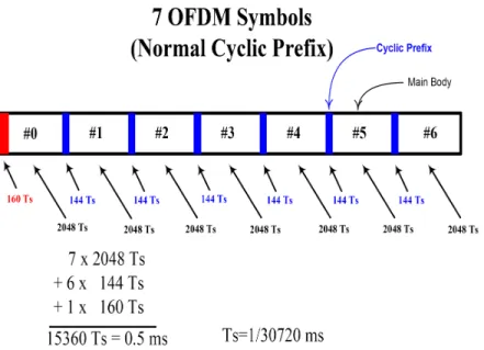
spread. To effectively combat the delay spread of the channel, the duration of the cyclic prefix should be greater than the duration of the multi-path delay spread. At the same time, cyclic prefix also represents an overhead which should be minimized. Two types of CP were specified in LTE, namely the normal CP and the extended CP. The structure of the symbols in a 0.5 ms slot with normal cyclic prefix is shown in Figure 2.7. In normal CP, each slot
Figure 2.7 Structure of the symbols in one slot with Normal Cyclic Prefix.
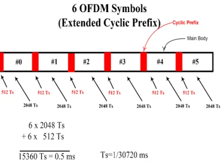
consists of 7 OFDM symbols, however, with extended CP (see Figure 2.7) only 6 OFDM symbols constitute one slot as shown in Figure 2.8. The duration of the first cyclic prefix and the subsequent prefixes in terms of sampling time (Ts) are also shown in Figure 2.8. Ts represents the basic time unit and is given by T s = 1/(15000× 2048) seconds. It can be noticed that the duration of the first cyclic prefix is larger than the subsequent cyclic prefixes. For the normal cyclic prefix the duration of the first cyclic prefix is defined as (160× Ts), whereas the subsequent cyclic prefixes the duration is only (144× Ts). For extended cyclic prefix, all prefixes have the same length which is equal to 512× Ts. The normal cyclic prefix length is proposed to be sufficient for the majority of radio environment scenarios, while the extended cyclic prefix is intended for radio environment with particularly high delay spreads. The cyclic prefix is generated by copying the end of the main body of the OFDM symbol.
Now, we explain how OFDM signal is generated. An OFDM symbol is based on the Inverse Fast Fourier Transform (IFFT), which is an operation of a transformation from frequency domain to time domain. Accordingly, the transmitted signal (the input signal to the OFDM block in Figure 2.4) is defined in the frequency domain. This means that the complex modu-lated symbols are considered as the coefficients in the frequency domain. The block diagram of an OFDM system is shown in Figure 2.9. The serial input data symbols (modulated synbbols) are firstly converted into a block of parallel complex S[k] = [S0[k], S1[k], S2[k], ..., SM −1[k]]T of dimension, where k is the index of an OFDM symbol containing M subcarriers. The M parallel data streams are first independently modulated (e.g. QPSK or M-QAM modulation) to form a vector of complex modulated symbols X[k] = [X0[k], X1[k], X2[k], ..., XM −1[k]]T.
Figure 2.8 Structure of the symbols in one slot with Extended Cyclic Prefix.
The X[k] vector is then applied to the input of an N -point Inverse Fast Fourier Trans-form (IFFT). The output of this operation is a set of N complex time-domain samples x[k] = [xo[k], x1[k], x2[k], ..., xN −1[k]]T. It is worth noting that in practical implementation of an OFDM system, the number of the points used by IFFT (N ) is greater than the number of the modulated subcarriers (M ) (i.e., N ≥ M). As shown in Figure 2.9, the un-modulated subcarriers are being padded with zeros. The next important operation in the geenration of an OFDM signal is the creation of a guard period at the beginning of each OFDM sym-bol x[k] by adding a Cyclic Prefix (CP). This CP is simply generated by taking the last G samples of the IFFT output and appending them at the beginning of x[k]. This yields the OFDM symbol in time domain as: [xN −G[k], ..., xN −1[k], x0[k], x1[k], x2[k], ..., xN −1[k]] as shown in Figure 2.9. The last step in the OFDM signal generation is the parallel to serial conversion of the IFFT output for transmissions through the radio interface.
The results of the OFDM operation in LTE is that the output signal now possesses two domains; the frequency domain and the time domain. The frequency domain is represented by successive subcarriers and the time domain is represented by successive OFDM symbols. In LTE, the bandwidth of a subcarrier is defined to be 15 KHz or 7.5 KHz. In the frequency domain, resources are grouped in units of 12 subcarriers. Thus, for a subcarrier spacing of 15 KHz, 12 subcarriers occupy a total of 180 KHz. The combination of 12 subcarriers in one slot (7 OFDM symbol) form what is called Resource Block (RB). The smallest of resource is called Resource Element (RE), which consists of one subcarrier for a duration of one OFDM Symbol. The structure of Resource Block for 15 KHz subcarrier spacing and its constituting
Figure 2.9 OFDM Signal Generation.
REs are shown in Figure 2.10 for illustration.
The number of RB in the frequency domain (NRB
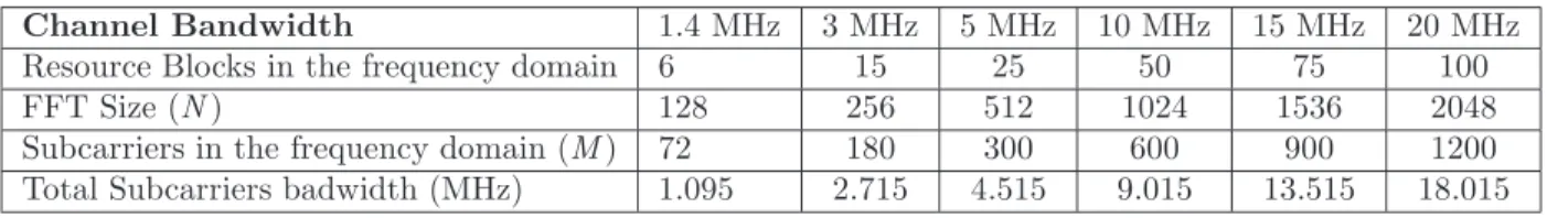
DL in Figure 2.10) depends on the trans-mission bandwidth. LTE is designed as a scalable system where the channel bandwidth is flexible. In fact, the standard defines six channel bandwidths. The possible channel band-width as defined in LTE for 15 KHz subcarriers spacing is shown in Table 2.1. The number of IFFT size is also shown in Table 2.1. For example in a 5 MHz bandwitdh, the IFFT size is set to 512 but the number of the used subcarriers is only 300, which represent 25 RB of 12 subcarriers each.
So far, we showed how the signal is generated to be sent over the radio interface. But how the data is organized and what kind of information are transmitted? In LTE, the physical layer receives different data types from the higher layer (MAC layer) which are organized in the form of different channels, called Transport Channels. The MAC layer itself receives data from the RLC layer in the form of Logical channels. Before sending the transport channels
Figure 2.10 LTE Resource Block.
Table 2.1 Resource Block as a function of Channel Bandwidth
Channel Bandwidth 1.4 MHz 3 MHz 5 MHz 10 MHz 15 MHz 20 MHz
Resource Blocks in the frequency domain 6 15 25 50 75 100
FFT Size (N ) 128 256 512 1024 1536 2048
Subcarriers in the frequency domain (M ) 72 180 300 600 900 1200
Total Subcarriers badwidth (MHz) 1.095 2.715 4.515 9.015 13.515 18.015
into the air, the physical layer process the transport channels to form Physical Channels. In addition to the physical channels, the physical layer needs to create its own signals to be sent over the air. The signal generated in the physical layer are called Physical Signals. The principle of channels generation and their placement with respect to different layers in LTE is illustrated in Figure 2.11.
Figure 2.11 Physical Channels and Physical Signals in LTE.
of physical channels in LTE and they are defined as follow:
Downlink Physical Signals: Three different physical signals are generated in the physical
layer:
1. Primary Synchronization Signal (PSS) 2. Secondary Synchronization Signal (SSS) 3. Reference Signals (RS)
PSS and SSS are the synchronization signals, used by the UE to achieve radio frame, subframe, slot and symbol synchronization in the time domain as well as the identification of the center of the channel bandwidth in the frequency domain. The reference signals (RS) on the other hand are used for channel estimation purposes and to support channel quality indicator (CQI) reporting and demodulation. They can also be used to support channel quality measurements for handover purposes.
Downlink Physical Channels: To carry the information blocks (data) received from the
MAC and higher layers, the number of downlink physical channels are defined in LTE. In total, six physical downlink channels are defined in LTE as follow:
1. Physical Broadcast Channel (PBCH)
2. Physical Control Format Indicator Channel (PCFICH) 3. Physical Hybrid ARQ Indicator Channel (PHICH)
4. Physical Downlink Control Channel (PDCCH) 5. Physical Downlink Shared Channel (PDSCH) 6. Physical Multicast Channel (PMCH)
The PBCH channel is used to broadcast the master information block (MIB) using trans-port and logical channels from higher layers (MAC and RLC layers). The PBCH is allocated the central 72 subcarriers belonging to the first 4 OFDM symbols of the second time slot of every 10 ms radio frame, which corresponds to 240 resource elements (RE) excluding the resource elements used by the RS ((72×4)−48), where 48 is the number of resource elements allocated to the Reference Signal. The PCFICH is used at the start of each 1 ms downlink subframe to signal the number of symbols used for the PDCCH. The PHICH is used to signal positive or negative acknowledgment for uplink data transferred on the uplink channel. To transfer the downlink control information, LTE uses the PDCCH channel. The PDSCH is the main data downlink channel in LTE. It is used for all user data. In addition to the user data, the system information and paging can also be sent with PDSCH channel. Finally, the PMCH is used to transfer the multimedia broadcast multicast service application data. More details about the use of each physical channel is given in [26] and [44]
2.4 MIMO-OFDM Schemes in LTE
Before explaining the MIMO-OFDM schemes as defined in LTE, we provide a brief the-oretical background of the advantages promised by multiple antenna techniques in wireless communication systems. In this context, the first part of this section covers the different con-figurations of using multiple antennas and their corresponding advantages from theoretical point of view. In the second part, the MIMO schemes as defined in LTE will be explained and the practical issues that cause the gap between the theoretical predictions and practical performances of such systems will be discussed.
Traditional wireless communications systems with one antenna at the transmitter and one antenna at the receiver (Single-Input Single-Output (SISO)) exploit time and/or frequency domains pre-processing the transmitted signal and decode the received data. Adding addi-tional antennas either at the transmitter or at the receiver creates an extra spatial dimension for signal coding and decoding processes. Hence, new areas of processing have emerged such as Space Time and Space frequency processing. Depending on the availability of additional antennas at the transmitter and/or at the receiver, such techniques are classified as Single In-put Multi OutIn-put (SIMO), Multi InIn-put Single OutIn-put (MISO) or Multi-InIn-put Multi-outIn-put (MIMO). Thus, in the case of having multiple antenna at the base station and only one antenna at the user’s equipment, the uplink (from user equipment to base station) is referred
to SIMO and the downlink (from base station to user equipment) is referred to MISO. It is worth noting that the term MIMO is sometimes also used in its widest sense, thus including SIMO and MISO as special cases.
When multiple antennas are available they can be used in different modes. Essentially, we can distinguish three different modes for multiple antennas, namely beam-forming mode,
diversity mode (receive and transmit) and multiplexing mode. In beam-forming mode the
advantage of using multiple antennas is evaluated by the so called Array gain. For diversity mode, the diversity gain is usually used to evaluate the advantage of this mode. Finally, the multiplexing gain is the benefit of using multiplexing mode. The principles of each mode and their advantages are described and explained in the following subsection:
2.4.1 Array Gain
The first approach of using multiple antennas is to send or to receive the same signals on all the antennas. In case of multiple receive antennas, a coherent combining techniques can be realized through spatial processing at the receive antennas side. In case of multiple transmit antennas, the coherent combining can be realized through spatial processing at the transmit antennas side. An example of receive coherent combining is the Maximum Ratio Combining (MRC) method and an example of transmit coherent combining is the concentration of energy in one or more directions, the so called beam-forming. In both cases, the results of combining will be reflected in an improvement of average SNR which is represented by an Array gain, also known as beam-forming gain. The array gain can be defined as the increase of the average SNR. In case of MRC, it can be shown that the array gain is constant and is equal to the number of antennas. To illustrate this, we should determine the combined SNR for a MRC system. To this end, let‘s suppose a MRC system with Nr branches (from one transmit antenna to Nr receive antennas).
2.4.2 Diversity Gain
For improving the communication reliability and reducing the sensitivity to the fading channel, we can send or receive the same signal on different antennas. By increasing the number of independent copies of the transmitted signal, the probabilities that at least one of the signals is not experiencing a deep fade increase and hence improving the quality and reliability of reception. This kind of transmissions is known as Diversity Mode and the associated gain is known as Diversity Gain. In other words, diversity gain corresponds to the mitigation of the effects of multipath fading, by means of transmitting or receiving over multiple antennas in which the fading is sufficiently de-correlated. The Diversity Gain can
be described either in terms of order, which represents the number of effective independently diversity branches or in terms of the slope of the Bit Error Rate curve as a function of the signal to noise ratio at high SNRs.
2.4.3 Multiplexing Gain
Multiple antennas can be used to send different signals on different antennas. The original high data rate signal is first divided into two low data rate signals and each signal is sent from different antennas. In the receiver side, the different signals are processed separately and multiplexed to recover the original high data rate signal. This method is known as Multiplexing mode and the associated gain is the Spatial Multiplexing gain. To evaluate this multiplexing gain, we use to the basics of shannon theory of capacity and spectral efficiency calculations. To this end, in the case of single antenna system (SISO), the data rate calculation is related to the Shannon capacity formula which yields the maximum achievable data rate of a single communication link in Additive White Gaussian Noise (AWGN) channel as [7]:
C = B log2(1 + γ) (2.1)
where C is the capacity, or maximum error free data rate; B is the bandwidth of the channel; and γ is the channel SNR. Since antennas diversity can increase the SNR linearly, diversity techniques can increase the capacity but in a logarithmic way with respect to the number of antennas. In other words, as the number of antennas increases, the data rate improvement rapidly diminishes. However, it can be concluded from the above equation that when the SNR is low, the capacity can increase linearly with SNR, since log(1 + x) ≈ x for small x [7]. The goal of multiplexing mode is to get more substantial data rate increase at high SNRs and to achieve this goal, the multiple antennas are used to send multiple independent signals. Therefore, the multiplexing mode has the ability to achieve a linear increase in the data rate with the number of antennas at moderate to high SNRs through the use of sophisticated signal processing algorithms. Specifically, it is shown that the capacity can be increased as a multiple of min(Nt, Nr) [7]. The capacity improvement is limited by the minimum of the number of antennas at either the transmitter or the receiver. As an example, a single user MIMO communications between a base station with four antennas and a user equipment with two antennas can support multiplexing of two data signals (also called data stream), and therefore doubling the data rate of the user equipment compared with a single antenna case. To achieve this maximum multiplexing gain, the different subchannels should experience different and de-correlated responses. In ideal case, in high SNR regions and in
rich scattering environments, the multiplexing gain will be equal to two. However in a real environment, a lower value of multiplexing gain can be observed.
Before describing the multiple antenna schemes in LTE, some terminology should be explained. Especially, four main terminologies have been introduced and are widely used in LTE, namely the Antenna ports; spatial layer ; the rank and the codeword .
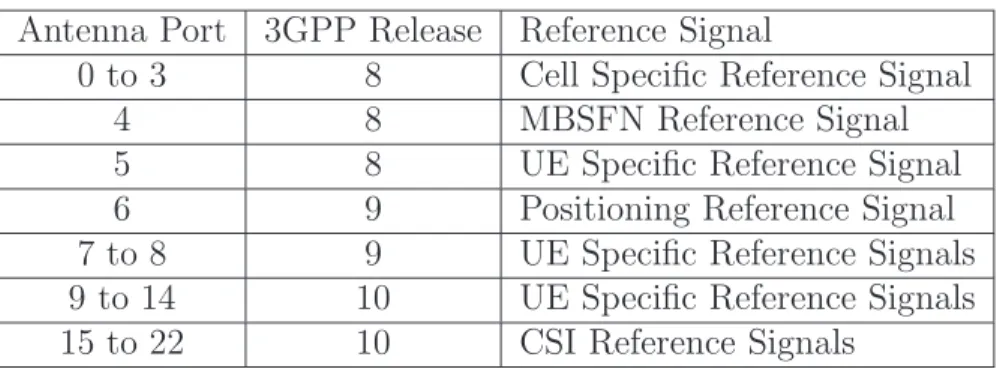
– Antenna ports: In LTE, the concept of antenna ports is used and should not be confused with the physical antenna elements. In fact, antenna ports are mapped into physical antenna elements. A downlink antenna port is defined by its associated Reference Signal. For example, antenna port 0 is associated with a cell specific Reference Signal, whereas antenna port 6 is associated with a positioning Reference Signal. The complete set of downlink antenna ports and their associated Reference Signals can be found in the Table 2.2:
Table 2.2 Antenna ports and their associated Reference Signals Antenna Port 3GPP Release Reference Signal
0 to 3 8 Cell Specific Reference Signal
4 8 MBSFN Reference Signal
5 8 UE Specific Reference Signal
6 9 Positioning Reference Signal
7 to 8 9 UE Specific Reference Signals 9 to 14 10 UE Specific Reference Signals 15 to 22 10 CSI Reference Signals
– Spatial Layer : In LTE, this term is used for one of different streams generated by spatial multiplexing. A layer can be described as a mapping of symbols into the transmit antenna ports. This operation is known as layer mapping where the modulated symbols are mapped into a number of layers where the number of layers are equal to the number of antenna ports.
– The Rank of the transmission is equal to the number of transmitted layers
– A CodeWord (CW) corresponds to a single Transport Block (TB) and it is an inde-pendently encoded data block delivered from the Medium Access (MAC) layer, and protected by a CRC.
Note that the number of codewords is always less than or equal to the number of layers, which in turn is always less than or equal to the number of antenna ports. For a rank greater than one, two codewords can be transmitted.
Based on the above mentioned theoretical background and terminologies, the MIMO schemes adopted for LTE Release 8 and 9 can be reviewed and explained. These schemes
relate to the downlink unless otherwise stated.
2.4.4 Diversity Schemes in LTE
In LTE, two main transmit diversity schemes are employed; the first one with 2 transmit antennas and the second one with 4 transmit antennas. Both schemes use only one data stream (one signal). In LTE, one data signal (also called data stream) is referred as one
codeword because only one transport block (TB) is used per data stream. The transport
block itself is defined as the unit of transmitted data and it corresponds to the Medium Access Control (MAC) layer Protocol Data Unit (PDU). The Transport Block unit can be passed from the MAC layer to the physical layer once per Transmission Time Interval (TTI), where a TTI is fixed to 1 ms, corresponding to the duration of one subframe as described in the LTE frame structure section. In order to ensure uncorrelated channels between different antennas and hence maximizing the diversity gain, the antennas should be well separated relative to the wavelength. The use of different antenna polarization is another approach that has demonstrate its efficiency in order to guarantee uncorrelated antennas. If a physical channel in LTE is configured for transmit diversity operation using two eNodeB antennas, the diversity scheme is called Space Frequency Block Codes (SFBC). The principle of operation of SFBC transmission is shown in Figure 2.12. As can be seen from Figure 2.12, the SFBC
diversity scheme is, in fact, exactly the frequency domain of the well known Space Time Block Codes (STBC), developed by Alamouti [5]. The fundamental characteristic of this family of code is that the transmitted diversity streams are orthogonal and they can be simply decoded using a linear receiver. It is worth noting that the STBC is already used in UMTS and it operates on pairs of adjacent symbols in the time domain. In LTE, however, the number of available OFDM symbols in a subframe is often an odd number, and hence the application of STBC is therefore not straight forward for LTE. Instead of adjacent symbols in the time domain, in LTE the diversity scheme operates on pairs of adjacent subcarriers, leading to a SFBC.
For SFBC transmission, the transmitted symbols from two eNodeB antenna ports on each pair of adjacent subcarriers are defined as follow [44]:
" y(0)(1) y(0)(2) y(1)(1) y(1)(2) # = " x1 x2 −x∗ 2 x∗1 # (2.2)
where y(p)(k) denotes the symbols transmitted on the kth subcarrier from antenna port p.
In matrix form, the transmitted space frequency block matrix can be generated as follows: y(0)(1) y(0)(2) y(1)(1) y(1)(2) = 1 √ 2 1 0 i 0 0 1 0 i 0 −1 0 i 1 0 −i 0 ℜ{x1} ℜ{x2} ℑ{x1} ℑ{x2} (2.3)
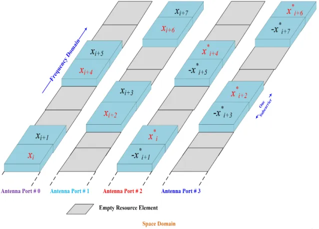
In case of four transmit antennas (antennas port 0 to 3) and in order to keep the or-thogonality of the code, the diversity scheme is simply a combination of SFBC scheme and Frequency Switched Transmit Diversity (FSTD) [44]. FSTD implies that a pair of modulated symbols are transmitted using SFBC scheme with two antennas whereas the other two anten-nas are not transmitting. In other words, in FSTD, the transmission is alternated between a pair of transmit antennas. This means that the first two symbols are transmitted on the antennas 0 and antenna 2, whereas nothing is transmitted on antennas ports 1 and 3. For the next two symbols, the antennas port 1 and 3 are used for transmission whereas antenna port 0 and 2 are not transmitting. The principle of FSTD diversity scheme is shown in Figure 2.13.The transmission matrix of the FSTD scheme can be then described as follow:
y(0)(1) y(0)(2) y(0)(3) y(0)(4) y(1)(1) y(1)(2) y(1)(3) y(1)(4) y(2)(1) y(2)(2) y(2)(3) y(2)(4) y(3)(1) y(3)(2) y(3)(3) y(3)(4) = x1 x2 0 0 0 0 x3 x4 −x∗ 2 x∗1 0 0 0 0 −x∗ 4 x∗3 (2.4)
where, as previously, y(p)(k) denotes the symbols transmitted on the kth subcarrier from antenna port p. This space frequency code is known as Frequency Switched Transmit Diver-sity (FSTD). It can be noticed form the code matrix that on each subcarrier slot, only two antennas are transmitting. For the first subcarrier slot, the antennas ports 1 and 2 are not transmitting any signals. We will show in the performance analysis in Chapter 3 that this scheme is equivalent to the 2× 2 scheme.
2.4.5 Spatial Multiplexing Schemes in LTE
In LTE, a spatial multiplexing mode can either use a single codeword mapped to all the available layers, or two codewords each mapped to one or more different layers. The main advantage of using only one codeword is a decrease in the amount of control signaling required, both for Channel Quality Indicator (CQI) reporting and for HARQ ACK/NACK feedback. In fact, in case of one single codeword, a single value of CQI is needed for all layers
and only one ACK/NACK would have to be signaled per subframe per user equipment (UE). In the case of using two codewords, more control signaling will be required but the advantage of such mapping is that significant multiplexing gain can be possible by using Minimum Mean Square Error and Successive Interference Cancelation (MMSE-SIC ) receiver. The codeword to layer mapping are shown in the Table 2.3 [44]:
Table 2.3 Codewords-to-layer Mapping in LTE
Transmission Rank Codeword 1 Codeword 2
Rank 1 Layer 1
Rank 2 Layer 1 Layer 2
Rank 3 Layer 1 Layer 2 and Layer 3
Rank 4 Layer 1 and layer 2 Layer 3 and layer 4
Depending on the availability of feed back from the user equipment, two modes of spatial multiplexing were defined in LTE, namely the open loop spatial multiplexing and the closed loop spatial multiplexing modes. The open loop spatial multiplexing mode was introduced in release 8 version of the 3GPP specification and it has not changed within the release 9 and 10 versions of specification. In open loop approach, the UE provides feedback to eNodeB in terms of Rank Indicator (RI) and Channel Quality Indicator (CQI). The RI feedback provides information about the suggested number of layers whereas the CQI provides information about the transport block size. In addition to the RI and CQI feedback, the closed loop spatial multiplexing provides an additional feedback in terms of Precoding Matrix Indicator. The precoding matrix, selected from a defined codebook, is used to form the transmitted layers. Each codebook consists of a set of predefined precoding matrices, with the size of the set being a tradeoff between the number of signaling bits required to indicate a particular matrix in the code book and the suitability of the resulting transmitted beam direction. The difference between open loop and closed loop is that in open loop the UE does not provide any information about the precoding matrix and it is generated independently, whereas in closed loop the precoding matrix is suggested by the UE. In case of two antenna ports, the 2× 2 spatial multiplexing always transfers 2 codewords using 2 layers during each subframe see Table 2.4 [26].
For the case of 4 antennas ports, one or two codewords can be transferred during each subframe. Table 2.5 summarizes the number of codewords and layers which are supported by a 4× 4 open loop spatial multiplexing.
Table 2.4 Codewords, layers and antenna ports for 2× 2 open loop spatial multiplexing.
Number of Codewords Number of Layers Number of Antenna Ports
2 2 2
Table 2.5 Codewords, layers and antenna ports for 4x4 open loop spatial multiplexing.
Number of Codewords Number of Layers Number of antennas ports
1 2
4 2
2 3
4
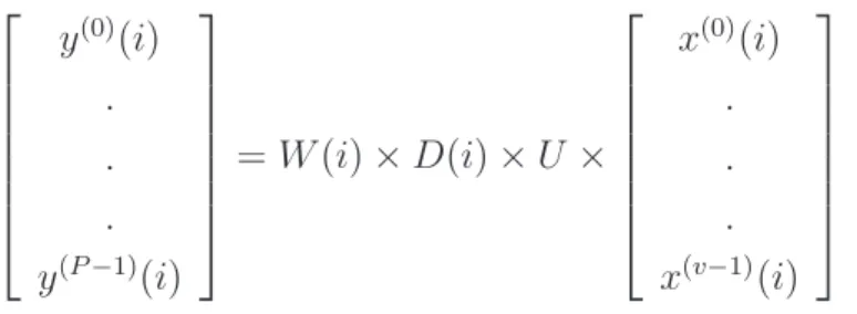
In open loop spatial multiplexing, instead of sending only two different signals, an ad-ditional precoding operation is applied to the transmitted signals before being transmitted onto the radio interface. The precoding scheme adopted for LTE is the so-called Large Delay Cyclic Delay Diversity (CDD). It should be noted that CDD is not used in LTE as an exact diversity scheme, as its name stipulate, but rather as a precoding scheme for spatial multi-plexing mode and that is why it was not introduced in the diversity schemes section. This CDD precoding is defined using the following equation [26]:
y(0)(i) . . . y(P −1)(i) = W (i)× D(i) × U × x(0)(i) . . . x(v−1)(i) (2.5)
where P is the number of output antenna ports, i is the sample number and v is the number of input layers. It is worth noting that the precoding multiplication is a function of the sample number ’i ’ but only the elements within the matrix U are not a function of the sample number ’i ’. To illustrate the principle of coding, let’s have a closed look to the case of two transmit antennas and two receive antennas as shown in Figure 2.14. For 2× 2 open loop spatial multiplexing, 3GPP specifies the W (i ); D(i ) and U matrix as [26]:
W (i) = √1 2 " 1 0 0 1 # (2.6) D(i) = " 1 0 0 e−j(π)i # (2.7) U = √1 2 " 1 0 1 e−j(π) # (2.8)
It can be noticed that the matrix W in case of 2× 2 open loop scheme is fixed and is not actually a function of ’i ’. The transmitted signal is then obtained by the product of W (i ),
D(i ) and U as [26]: W (i)× D(i) × U = √1 2 " 1 0 0 1 # × " 1 0 0 e−j(π)i # ×√1 2 " 1 0 1 e−j(π) # (2.9)
Figure 2.14 2× 2 Open Loop Spatial Multiplexing with Large-Delay CDD Precoding.
The results of 2.9 depends on the indices ’i ’ of transmitted symbols and hence two different results are possible, one for odd number and one for even number. For the odd number of ’i ’, is then:
W (i)× D(i) × U = 1 2 " 1 1 1 −1 # (2.10)
For even number of ’i ’, the results is found to be:
W (i)× D(i) × U = 1 2 " 1 1 −1 1 # (2.11) The summary of the described layer mapping and precoding for the 2×2 open loop spatial multiplexing with two codewords is shown in Figure 2.14:
CHAPTER 3
PERFORMANCE EVALUATION OF MIMO SYSTEMS IN LTE
3.1 Introduction
Two main and fundamental key performance indicators which have bee used to evaluate the performance of the wireless communication systems are the Bit Error Rate (BER)[39], and the data throughput or its related channel capacity bound. For a system using one an-tenna at the transmitter and one anan-tenna at the receiver and in non fading AWGN channel, the evaluation of the BER for most of the known modulation schemes is well known [39]. Using more antennas at the transmitter and at the receiver and also in more realistic fad-ing channel models, such as Rayleigh, Rician and Nakagami, the evaluation becomes more complex and necessitates the use and the development of advanced mathematical tools. In this context, the theory of BER evaluation had experienced an important evolution during the past decade. Initially, the evaluation of the BER performance was based on a classical approach where the Gaussian Q-function (also known as Gaussian Probability Integral) was used (Chapter 4 in [6]). However, this classical approach suffers from two main disadvantages when extended to more general complex channels especially those experiencing fading. The first disadvantage is related to the upper infinite limit where it requires a truncation in case of numerical evaluation. The second and more significant disadvantage is related to the pres-ence of the argument of the function as the lower limit of the integral. In general case, the lower limit in the integral depends on other random parameters and this dependency requires statistical averaging over their probability distribution which poses analytical difficulties. In other words, to evaluate the average error probability in the presence of fading channels, the Gaussian Q-function should be averaged over the fading amplitude distribution. To overcome the mentioned disadvantages, an alternative representation of the Gaussian Q-function has been developed and since then widely used for the evaluation of the BER (See Appendice B). In the alternative representation of the Q-function, the argument of the function is nei-ther the upper nor the lower limit of the integral. Using the alternative representation of the Gaussian Q-function, the evaluation of the average error probability becomes a problem of evaluation of the integral of the Laplace transform of the probability density function of the SNR distribution, which represents the Moment Generation Function (MGF). This new approach of representation of the Q-function is particularly effective for evaluation of the average error probability of MIMO schemes where the probability density function of
the SNR has more complicated form like the N order Chi-squared distribution. In [29], the method of MGF was used to evaluate the BER of three phase relaying wireless system using the Alamouti STBC code [5]. Instead of using the alternative representation of the Gaussian Q-function, in [30], the Marcum Q-function was used to derive an approximate expression of BER analysis of Alamouti-MRC scheme with imperfect channel state information in Rician fading channel. In LTE the BER is mainly evaluated by simulation and to the best of our knowledge, the BER analysis is rarely treated in the literature. One of our goal is to develop in this thesis some closed form expressions of the BER for the main MIMO schemes as used in LTE.
To study the performance of LTE systems, a MATLAB based downlink physical layer simulator (Appendice C) for Link Level Simulation (LLS) has been developed in [32] [36]. A System Level Simulation of the Simulator is also available [25]. The main goal in developing the LTE simulator was to facilitate comparison with the work of different research groups and it became publicly available for free under academic non-commercial use license [36]. The main features of the simulator are adaptive coding and modulation, MIMO transmission and scheduling. As the simulator includes many physical layer features, it can be used for different applications in research [25]. In [47], the simulator was used to study the channel estimation of OFDM systems and the performance evaluation of a fast fading channel estimator was presented. In [42] and [41], a method for calculating the Precoding Matrix Indicator (PMI), the Rank Indicator (RI), and the Channel Quality Indicator (CQI) were studied and analyzed with the simulator.
The remainder of this chapter is organized in two main parts. The first part (i.e., section 3.2) is dedicated to the analysis of BER of the major MIMO schemes included in LTE. In subsection 3.2.1, we set up the system and channel model used in the simulation. In subsection 3.2.2, we present a performance analysis for the average BER of SFBC and FSTD MIMO schemes. The numerical and simulation results and discussions are presented in subsection 3.2.3. The second part of this chapter (i.e., section 3.3 and section 3.4) considers the capacity and data throughput evaluation. The capacity analysis is presented in section 3.3.2 followed by the data throughput evaluation in Section 3.4. The simulations results as well as the discussions of the obtained results are presented in subsection 3.4.1.
3.2 BER Analysis of LTE MIMO Schemes 3.2.1 System Model
In a MIMO system with Nr receive antennas and Nt transmit antennas, the relation between the received and the transmitted signals on OFDM subcarrier frequency k (k ∈ 1, ..., N), at sampling instant time n is given by
yk,n = Hk,nxk,n+ nk,n (3.1)
where yk,n ∈ CNr×1 is the received output vector, Hk,n ∈ CNr×Nt represents the channel
matrix on subcarrier k at instant time n, xk,n ∈ CNt×1 is the transmit symbol vector and
nk,n ∼ CN (0, σ2
n.I) is a white, complex valued Gaussian noise vector with variance σn2 and I is an Nr × Nr identity matrix. Assuming perfect channel estimation, the channel matrix and noise variance are considered to be known at the receiver. A linear equalizer filter given by a matrix Fk,n ∈ CNr×Nr is applied on the received symbol vector yk,n to determine the
post-equalization symbol vector rk,n as follows [41]
rk,n = Fk,nyk,n = Fk,nHk,nxk,n+ Fk,nnk,n. (3.2)
The Zero Forcing (ZF) or Minimum Mean Square Error (MMSE) design criterion are typically used for the linear receiver and the input signal vector is normalized to unit power [53]. In MIMO-OFDM systems, the key factor of link error prediction and performances is the signal to noise ratio (SNR) which represents the measurement for the channel quality information. In this study, the SNR is defined as follows [32]:
γk,n = kHk,nxk,nk 2 F Ntσ2 n (3.3)
where xk,n is the transmitted symbol vector,k.k2F is the squared Frobenius norm of a matrix. 3.2.2 Average BER Performance analysis for several M-QAM Schemes
In this section, a Bit Error Rate (BER) analysis is presented for Input Multiple-Output (MIMO) schemes in the 3GPP Long Term Evolution (LTE) system. Analytical expressions for the average BER of the system are derived over flat Rayleigh fading channels for two different MIMO schemes as defined in LTE, assuming M-ary quadrature amplitude modulation (M-QAM) schemes and are evaluated numerically. The analysis is based on the probability density function of the instantaneous Signal to Noise Ratio and the Moment