DEVELOPMENT OF THE PIEZOELECTRIC PROPERTIES OF
POLY(VINYLIDENE FLUORIDE) BASED FERROELECTRICS AND
FERROELECTRETS USING FILLERS AND MECHANICAL STRETCHING
NUSRAT JAHAN
DÉPARTEMENT DE GÉNIE CHIMIQUE ÉCOLE POLYTECHNIQUE DE MONTRÉAL
THÈSE PRÉSENTÉE EN VUE DE L’OBTENTION DU DIPLÔME DE PHILOSOPHIAE DOCTOR
(GÉNIE CHIMIQUE) AVRIL 2018
UNIVERSITÉ DE MONTRÉAL
ÉCOLE POLYTECHNIQUE DE MONTRÉAL
Cette thèse intitulée:
DEVELOPMENT OF THE PIEZOELECTRIC PROPERTIES OF
POLY(VINYLIDENE FLUORIDE) BASED FERROELECTRICS AND
FERROELECTRETS USING FILLERS AND MECHANICAL STRETCHING
présentée par : JAHAN Nusrat
en vue de l’obtention du diplôme de : Philosophiae Doctor a été dûment acceptée par le jury d’examen constitué de :
M. TAVARES Jason-Robert, Ph. D., président
M. AJJI Abdellah, Ph. D., membre et directeur de recherche M. MIGHRI Frej, Ph. D., membre et codirecteur de recherche M. RODRIGUE Denis, Ph. D., membre et codirecteur de recherche M. CICOIRA Fabio, Ph. D., membre
DEDICATION
ACKNOWLEDGEMENTS
I begin by thanking Allah, the most gracious and the most merciful.First and foremost, I would like to express my heartiest gratitude to my supervisors Prof. Abdellah Ajji, Prof. Frej Mighri and Prof. Denis Rodrigue. I consider myself very fortunate to have such amazing mentors from the very beginning of this journey, who guided and supported my development as a researcher with an extraordinary show of patience and kindness. They are a true inspiration for me to grow.
I am very grateful to Prof. Charles Dubois from Chemical engineering department, polytechnique Montréal for allowing me to use his lab equipements.
I would like to thank Prof. Daniel Therriault and Dr. Sampada bodkhe from Mechanical engineering department of polytechnique Montréal who kindly allowed and helped me to work in their lab.
My heartiest gratitude goes to Prof. Mohamad Sawan and Mr. Laurent Mouden for giving access to their lab and allowing me to use their equipments.
I would like to thank other professors and staff of Chemical engineering department for providing a world-class environment and facilities for graduate research. I would also like to specially thank Mrs. Claire Cerclé, Mr. Richard Silverwood, Mr. Redouane Boutrouka and Mr. Jean Huard. I would like to thank all my friends and colleagues for their support and feedback over the years. Last but not the least, I am eternally grateful to my parents, who made their lifelong sacrifices to see me happy and successful. My eternal thanks goes to my siblings who were always there with me in spirit. I am very thankful to my mother-in-law who has been a great support for me. I thank my husband Sazzad, who has been on my side with her gracious support and encouragement.
RÉSUMÉ
Les polymères piézoélectriques sont très utiles pour plusieurs applications électrochimiques vu leur forte réponse piézoélectrique, leur flexibilité, leur légèreté ainsi que leur formabilité. En plus des céramiques ferroélectriques, les polymères ferroélectriques (comme le PVDF) et les ferroélectrets sont aussi populaires comme nouveau groupe de piézoélectrique. L’intérêt pour les ferroélectriques basés sur le b-PVDF est dû à la facilite de leur préparation avec une réponse piézoélectrique usable, en plus des avantages de polymères déjà cités. L’incorporation d’une nanocharge (comme le PZT, les nanotubes de carbone, l’argile, les nanoparticules ferrite, la charge pour céramique BaTiO3) dans le PVDF est une des approches faciles pour produire une phase b dans le PVDF souvent suivi par un étirement mécanique. Ces charges aident à la nucléation de la phase b dans la matrice de PVDF tandis que l’étirement mécanique subséquent aide à aligner les dipôles dans une certaine mesure. Par conséquent, le but de la première partie de cette étude est de préparer des films ferroélectriques B-PVDF en incorporant une charge hybride (micro-CaCO3+ nanoargile) suivi par un étirement mécanique. La nanoargile, l’une des charges rentables les plus utilisées, est capable de nucleer le b-PVDF. L’amélioration synergétique dans la formation de la phase b ainsi que les propriétés mécaniques, électriques et piézoélectriques ont été rapportées dans cette partie de l’étude. De plus, l'influence de l'étirement mécanique subséquent (le rapport de tirage, R (longueur finale / longueur initiale)) a également été étudié. FTIR et XRD sont utilisés pour déterminer la teneur en phase b dans les deux échantillons étirés et non étirés. Alors que les propriétés de traction montrent une diminution progressive, la constante diélectrique a augmenté progressivement avec l'augmentation de la teneur en CaCO3 dans la charge hybride. Le coefficient d33 piézoélectrique maximum de 30 pC/N est obtenu pour des films composites hybrides étirés. D'autre part, les ferroélectrets sont un autre type de films polymères fonctionnels avec une structure cellulaire hétérogène et des moments dipolaires internes quasi-permanents. La piézoélectricité dans les ferroélectrets provient de la variation des moments dipolaires avec l’application d’une charge mécanique. Au cours des dernières décennies, les films de polypropylène cellulaire (PP) ont été les ferroélectrets les plus populaires et les plus étudiés et ont déjà des applications commerciales. Alors que le coefficient piézoélectrique d33 des ferroélectrets PP peut présenter jusqu'à 1000 pC/N ou plus, leur température de fonctionnement est assez faible, inférieure à 60 °C. Les fluoropolymères récemment développés, i.e. les ferroélectrets à base de polytetrafluoroethylene (PTFE) et de
fluoroethylene propylène (FEP), présentent une forte réponse piézoélectrique et une excellente stabilité thermique. Cependant, le traitement de ces ferroélectrets de fluoropolymères en utilisant une technique de fabrication commercialement viable telle qu'une extrusion de film coulé pose quelques défis en raison de leur viscosité très élevée à l'état fondu, de leur haute température de fabrication, de leur tendance à la dégradation et de leur faible élongation à la traction. Par conséquent, dans cette partie de l'étude, un nouveau ferroélectret thermiquement stable a été étudié en utilisant une technique de traitement commerciale avec une forte réponse piézoélectrique. L'extrusion par coulée du mélange polymère / charge suivie d'un étirage mécanique est l'une des techniques prometteuses pour préparer un polymère cellulaire. Les charges à l'échelle micrométrique sont habituellement utilisées pour créer des vides à partir de la délamination interfaciale sous contrainte appliquée. Le fluorure de polyvinylidène (PVDF) est un fluoropolymères qui est facilement transformable à l'état fondu par rapport aux autres fluoropolymères et qui présente d'excellentes propriétés physiques, chimiques et électriques. Un procédé "d'extrusion-étirage-gonflage" a été suivi pour préparer une structure cellulaire dans des films de PVDF. Des films solides de PVDF / charge hybride (micro-CaCO3 + nanoargile) ont été extrudés et ensuite étirés pour créer la structure cellulaire initiale à l'intérieur des films. Tandis que le CaCO3 agit comme centre de nucléation des vides, la nanoargile augmente l'etirabilité des films de PVDF fortement chargés en CaCO3. L'expansion de diffusion de gaz (GDE) ou le gonflage contrôlé est préformé pour ajuster les dimensions des vides à des vides en forme de lentilles conduisant à des modules d'élasticité inférieurs et à une piézoélectricité plus forte. De toute évidence, les caractéristiques de perméation de gaz dans les polymères polaires sont différentes de celles des polymères non polaires en raison de l'interaction polymère / gaz différente et de la forte dépendance des propriétés piézoélectriques finales des ferroélectrets en la morphologie cellulaire comme la taille, la forme et la distribution des vides. Par conséquent, deux gaz de gonflage différents, à savoir le N2 neutre et le CO2 polaire, sont utilisés avec différentes stratégies de gonflage. Plusieurs combinaisons de la pression, la température et leur mode d'application (direct ou par paliers) sont examinées pour optimiser le niveau de gonflage. Les films gonflés sont ensuite soumis à une charge corona à température ambiante pour créer les dipôles à l'intérieur des vides. Enfin, les ferroélectrets de PVDF montrent un coefficient piézoélectrique d33 atteignant 251 pC/N avec un gonflage N2 et 327 pC/N pour le traitement au CO2. Comme prévu, les ferroélectrets de PVDF présentent une meilleure stabilité thermique que le PP, le PETP, le COP et le PEN et aussi
élevés que le Teflon. Les échantillons chargés à température ambiante pourraient avoir leur température de travail jusqu'à 120 °C.
ABSTRACT
Piezoelectric polymers are very useful in various electromechanical applications because of their strong piezoelectric response, flexibility, lightweight and formability. In addition to ferroelectric ceramics, ferroelectric polymers (such as PVDF) and ferroelectrets are also popular as a new group of piezoelectrics. Ferroelectrics based on b-PVDF are interesting due to the ease of preparation with usable piezoelectric response in addition to the above mentioned advantages of polymers. Incorporating nanofillers (e.g. ceramic filler-BaTiO3, PZT, carbon nanotube, clay, ferrite nanoparticles etc.) into PVDF is one of the facile ways to produce b phase in PVDF often followed by mechanical stretching. While fillers nucleate b phase in the PVDF matrix, subsequent mechanical stretching helps in aligning the dipoles to some extent. Therefore, the aim of the first part of this study is to prepare ferroelectric b-PVDF films by incorporating a hybrid filler (micro-CaCO3+ nanoclay) followed by mechanical stretching. While nanoclay is one of the most widely used cost-effective fillers capable of nucleating b-PVDF, synergistic improvement in b phase formation as well as in mechanical, electrical and piezoelectric properties of hybrid composites have been reported in this part of the study. Additionally, the influence of subsequent mechanical stretching e.g. draw ratio, R (final length/initial length), has also been investigated. FTIR and XRD are employed to determine the b phase content in both stretched and unstretched samples. While the tensile properties show a gradual decrease, dielectric constant increased gradually with increasing CaCO3 content in the hybrid filler. The maximum piezoelectric d33 coefficient of 30 pC/N is obtained for stretched hybrid composite films. Ferroelectrets, on the other hand, are another type of functional polymer films with heterogeneous cellular structure and internal quasi-permanent dipole moments. The piezoelectricity in ferroelectrets originates from the change in dipole moments under an applied mechanical stress. Over the past few decades, cellular polypropylene (PP) films have been the most popular and widely investigated ferroelectrets and are already in commercial applications. While the piezoelectric d33 coefficient of PP ferroelectrets could exhibit up to 1000 pC/N or more, their working temperature is quite low, not higher than 60 °C. Recently developed fluoropolymer i.e. polytetrafluoroethylene (PTFE) and fluoroethylene propylene (FEP) based ferroelectrets exhibit strong piezoelectric response and excellent thermal stability. However, processing these fluoropolymer ferroelectrets using commercially viable manufacturing technique such as cast film extrusion poses few challenges because of their very
high melt viscosity, high manufacturing temperature, degradation tendency and low tensile elongation. Therefore, in this part of the study, a new thermally stable ferroelectret has been investigated using commercial processing technique with strong piezoelectric response. Cast extrusion of the polymer/filler mixture followed by mechanical stretching is one of the promising techniques for preparing a cellular polymer. Micron scale fillers are usually employed for creating voids from interfacial delamination under applied stress. Polyvinylidene fluoride (PVDF) is a fluoropolymer which is easily melt-processable than other fluoropolymers and showing excellent physical, chemical and electrical properties. An “extrusion-stretching-inflation” process has been followed to prepare a cellular structure in PVDF films. Solid PVDF/hybrid filler (micro-CaCO3 + nanoclay) films were extruded and subsequently stretched to create the initial cellular structure inside the films. While CaCO3 acts as void nucleation centers, nanoclay increases the stretchability of the highly CaCO3 filled PVDF films. Gas diffusion expansion (GDE) or controlled inflation is preformed to adjust the voids dimensions to lens-shaped voids leading to lower elastic moduli and stronger piezoelectricity. Obviously, the gas permeation characteristics in polar polymers is different than non-polar polymers because of their different type of polymer/gas interaction and the final piezoelectric properties of the ferroelectrets strongly depend on the cellular morphology such as void size, shape and distribution. Therefore, two different inflation gases i.e. neutral N2 and polar CO2 are used with various inflation strategies. Combination of pressure, temperature and their way of application (direct or step-wise) is examined for various times to optimize the inflation level. The inflated films are then subjected to corona charging at room temperature to create the dipoles inside the voids. Finally, PVDF ferroelectrets show piezoelectric d33 coefficient as high as 251 pC/N with N2 inflation and 327 pC/N for CO2 treatment. As expected, PVDF ferroelectrets exhibit better thermal stability than PP, PETP, COP and PEN and as high as Teflon. Samples charged at room temperature have their working temperature up to 120 °C.
TABLE OF CONTENTS
DEDICATION……….…………. III ACKNOWLEDGEMENTS……….………..….. IV RÉSUMÉ……….……... V ABSTRACT……….……….….VIII TABLE OF CONTENTS………... X LIST OF TABLES ……… XIV LIST OF FIGURES ……….……... XV LIST OF ABBREVIATIONS ………..….……… XIXCHAPTER 1 INTRODUCTION………1
CHAPTER 2 LITERATURE REVIEW………...….4
Background of Piezoelectricity ... 4
Definition of Piezoelectric Coefficient ... 5
Typical Piezoelectric Materials ... 7
2.3.1 Crystal- Rochelle Salt ... 7
2.3.2 Ceramic - Lead Zirconate Titanate (PZT) ... 7
Ferroelectric Polymer- b-Polyvinylidene Fluoride (b-PVDF) ... 8
2.4.1 Formation of b-PVDF ... 10
Ferroelectret ... 13
2.5.1 Piezoelectric Coefficient of Ferroelectret ... 14
2.5.2 Typical Ferroelectret Materials ... 15
2.5.2.1 Polypropylene (PP) ... 15
2.5.2.2 Polyethylene Terephthalate (PETP) ... 16
2.5.2.3 Fluoroethylene Propylene (FEP) and Polytetrafluoroethylene (PTFE) ... 16
2.5.3 Ferroelectret Formation ... 17
2.5.3.1 Cellular Structure Formation via Stretching or Foaming ... 18
2.5.3.2 Gas Diffusion Expansion (GDE) or Inflation ... 19
Summary ... 25
CHAPTER 3 : OBJECTIVES AND ORGANIZATION OF THE ARTICLES ………..27
3.1 Objectives ... 27
3.1.1 General Objective ... 27
3.1.2 Specific Objectives ... 27
3.1.3 Organization of Articles ... 28
CHAPTER 4 ARTICLE 1 : ENHANCED ELECTROACTIVE b PHASE IN THREE PHASE PVDF/CACO3/NANOCLAY COMPOSITES: EFFECT OF MICRO-CACO3 AND UNIAXIAL STRETCHING... 29 Abstract ... 30 Introduction ... 30 Experimental ... 33 4.3.1 Materials ... 33 4.3.2 Film Preparation ... 33 4.3.3 Uniaxial Stretching ... 34 4.3.4 Characterization Techniques ... 34
Results and Discussion ... 35
4.4.1 Infrared Spectroscopy : Analysis of the Crystalline Structure ... 35
4.4.2 X-ray Diffraction : Analysis of Crystalline Structure ... 40
4.4.3 Differential Scanning Calorimetry ... 43
4.4.4 Flexibility Test ... 48
Conclusion ... 49
Acknowledgement ... 50
CHAPTER 5 ARTICLE 2: SYNERGISTIC IMPROVEMENT OF PIEZOELECTRIC PROPERTIES OF PVDF/CACO3/MONTMORILLONITE HYBRID NANOCOMPOSITES....51
Abstract ... 52
Introduction ... 52
Experimental ... 54
5.3.1 Materials ... 54
5.3.3 Uniaxial Stretching ... 55
5.3.4 Characterization Techniques ... 55
Results and Discussion ... 56
5.4.1 Tensile Properties ... 56
5.4.2 Dynamic Mechanical Analysis (DMA) ... 58
5.4.3 Dielectric Properties ... 60
5.4.4 DC Volume Resistivity ... 64
5.4.5 Piezoelectric Properties ... 67
Conclusion ... 69
Acknowledgement ... 70
CHAPTER 6 ARTICLE 3: EFFECT OF THE INFLATION STRATEGY ON THE PIEZOELECTRIC RESPONSE OF CELLULAR PVDF FERROELECTRET………71
Abstract ... 72 Introduction ... 72 Experimental procedure ... 74 6.3.1 Materials ... 74 6.3.2 Film Preparation ... 74 6.3.3 Uniaxial Stretching ... 75
6.3.4 Gas Diffusion Expansion ... 75
6.3.5 Scanning Electron Microscopy ... 77
6.3.6 Corona Discharge ... 78
6.3.7 Quasi-static Piezoelectric Coefficient (d33) ... 78
Results and Discussion ... 79
Conclusion ... 86
Acknowledgement ... 86
Supporting information ... 87
6.7.1 Supporting information content ... 87
CHAPTER 7 ARTICLE 4: THERMALLY STABLE CELLULAR PVDF FERROELECTRETS: OPTIMIZATION OF CO2 DRIVEN INFLATION PROCESS …………89
Abstract ... 90
Experimental Procedure ... 92
7.3.1 Materials ... 92
7.3.2 Sample Preparation ... 92
Results and Discussion ... 94
7.4.1 Morphological Analysis ... 94
7.4.2 Piezoelectric d33 Coefficient ... 100
7.4.3 Thermal Stability of the Ferroelectret ... 101
Conclusion ... 106
Acknowledgement ... 107
Supporting information ... 108
7.7.1 Supporting information content ... 108
7.7.1.1 Film preparation ... 109
7.7.1.2 Uniaxial stretching ... 109
7.7.1.3 Gas diffusion expansion (GDE) ... 109
7.7.1.4 Scanning Electron Microscopy ... 111
7.7.1.5 Quasi-static piezoelectric coefficient (d33) ... 111
CHAPTER 8 GENERAL DISCUSSION………...…114
CHAPTER 9 CONCLUSION AND RECOMMENDATIONS……….…...….119
Conclusions ... 119
Original Contribution ... 121
Recommendation ... 122
REFERENCES ………..….…...123
LIST OF TABLES
Table 2.1: Comparison of the piezoelectric d33 coefficients for common piezoelectric materials. 15
Table 2.2: Properties of PTFE and FEP [10]. ... 17
Table 4.1: Details of composite samples composition used in this study.Error! Bookmark not
defined.
Table 4.2: Effect of fillers and draw ratio on the F(b) of neat PVDF and its composites. ... 38 Table 4.3: Coherence length and amount of a and b phase of neat PVDF and its composites. .... 42 Table 4.4: Melting enthalpy and crystallinity data for both as extruded and stretched samples. .. 47
Table 5.1: Details of the sample composition used in this study. ... 55
Table 5.2: Tensile properties of extruded neat PVDF and its composites. ... 57
Table 5.3: Percentage of b phase, crystallinity and crystallite size of pristine PVDF and its nanocomposites obtained in the previous study [128]. Data are presented for both stretched and unstretched composites. ... 62
Table 5.4: Piezoelectric coefficient d33 and dc volume resistivity rv of both stretched and unstretched pristine PVDF and its composites. ... 67
Table 7.1: Crystallinity data for both N2 and CO2-inflated samples. ‘X’ represents the sample without inflation and the GDE procedures described in Figure 7.1. ... 103
LIST OF FIGURES
Figure 2.1: Schematic of the piezoelectric effect. (a) direct effect (voltage induced by mechanical force) and (b) indirect effect (strain induced by an electrical field). ... 4 Figure 2.2: Schematic of the transduction mode of piezoelectric materials. (a) 33 mode and (b)
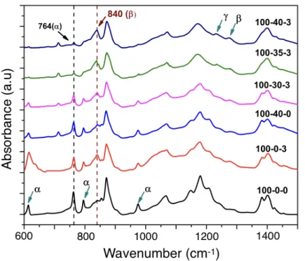
-31 mode. ... 7 Figure 2.3: PVDF unit cell (-CH2-CF2), reprinted from [30]. ... 8 Figure 2.4: Schematic of the chain conformation of PVDF, reprinted form [37]. ... 9 Figure 2.5: Illustration of the evolution of the piezoelectric effect from molecular dipoles in PVDF. (a) molecular dipoles oriented randomly before poling, (b) preferential alignment of the dipoles due to poling, and (c) increased polarization due to decreased thickness, reprinted from [30]. ... 10 Figure 2.6: Mechanism of PVDF chain conformation change to TTT (b phase) in presence of (a) surface modified ferrite nanoparticle, reprinted from [65] and (b) montmorillonite clay, reprinted from [14]. ... 12 Figure 2.7: Schematic presentation of a ferroelectret. (a) macroscopic dipoles are formed in the voids at the gas/polymer interface after charging and (b) under mechanical stress, change in dipole moment causes the flow of charges, reprinted from [30]. ... 14 Figure 2.8: Chemical structures of (a) PTFE and (b) FEP. ... 17 Figure 2.9: Schematic presentation of the fabrication process of ferroelectret using filler particles, reprinted from [2]. ... 18 Figure 2.10: Schematic presentation of the correlation between the piezoelectric activity and elastic stiffness of a cellular film as a function of sample density and cellular morphology, reprinted from [26]. ... 20 Figure 2.11: Change in thickness and density of cellular PP film as a function of heat treatment temperature after inflation at 50 bar in N2 gas, reprinted from [17]. ... 21 Figure 2.12: Scanning electron micrographs of the cross-section of cellular PP. Top image: film without inflation, and bottom image: film inflated at 5 MPa followed by a heat treatment at 100 °C, reprinted from [18]. ... 22 Figure 2.13: Isothermal d33 decay curve of cellular PP and porous PTFE aged at 80 °C, reprinted from [86]. ... 25 Figure 4.1: FTIR spectra of extruded neat PVDF and its various composites. ... 36
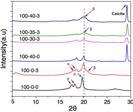
Figure 4.2: FTIR spectra of stretched (a) 100-0-3, (b) 100-40-3 samples and (c) Comparison of b phase content of three phase 100-40-3 composite with pristine PVDF and two phase composites drawn at different ratios. ... 39 Figure 4.3: XRD patterns for pristine PVDF and its composite films for phase detection. ... 41 Figure 4.4: XRD spectra of stretched samples (a)100-0-3 and (b) 100-40-3. ... 42 Figure 4.5: DSC thermograms of pure PVDF and its composites with various fraction of fillers.44 Figure 4.6: DSC thermograms of stretched samples (a)100-0-0, (b) 100-0-3 and (c) 100-40-3. .. 47 Figure 4.7: Digital photographs showing the flexible nature of 100-0-0, 100-0-3, 100-40-0 and 49 Figure 5.1: Tensile stress-strain curves of neat PVDF and its nanocomposites in the extrusion direction. ... 57 Figure 5.2: Temperature dependence of tensile storage modulus of (a) unstretched extruded samples, and (b, c) 100-0-3 and 100-40-3 samples, respectively stretched at various draw ratios, R. ... 59 Figure 5.3: SEM images of (left) 100-0-3 nanocomposite and (right) 100-40-3 composite. ... 60 Figure 5.4: Dielectric constant (e’) (a) and dielectric loss (tand) (b) of unstretched pristine PVDF and its composites. ... 61 Figure 5.5: Dielectric constant (e’) (a, b) and dielectric loss (tand) (c,d) of 100-0-3 and 100-40-3 composites, respectively stretched at different draw ratios. ... 64 Figure 5.6: Volume resistivity of (a) unstretched extruded neat PVDF and its composites, and (b) stretched 100-0-3 and 100-40-3 composites. ... 65 Figure 5.7: d33 values of (a) unstretched nanocomposites including neat PVDF and (b) stretched 100-0-3 and 100-40-3 composites. ... 69 Figure 6.1: Schematic diagrams of the different inflation procedures for the gas diffusion expansion (GDE). ... 77 Figure 6.2: Ellipses fitting of the voids using the software ImageJ. ... 78 Figure 6.3: The change in sample thickness (Dt) of cellular PVDF electrets due to inflation using various GDE procedures. Each measurement is the average of at least 3 measurement points on the samples. ... 80 Figure 6.4: Scanning electron micrographs of the cross-section of cellular PVDF samples inflated at various GDE procedures. ‘x’ represents the cross-section of sample without inflation
treatments after stretching. The other micrographs represents the samples treatd with various inflation procedures. See supporting information for larger area micrographs. ... 82 Figure 6.5: Void height distribution for samples treated by various inflation techniques obtained by analyzing their respective SEM images. ... 82 Figure 6.6: Piezoelectric d33 coefficients of the cellular PVDF electrets obtained after various inflation treatments followed by corona charging. ... 83 Figure 7.1: Schematic representation of the inflation procedures, reprinted from [157]. ... 93 Figure 7.2: Scanning electron micrographs of the cross-section of the N2-inflated samples, reprinted from [157]. The roman numbers on the top right corner represents the inflation procedures explained in earlier section as well as in Figure 7.1. ‘X’ represents the sample without any inflation treatment. ... 95 Figure 7.3: Scanning electron micrographs of the cross-section of the CO2-inflated samples. The roman numbers on the top right corner represents the inflation procedures of Figure 7.1 and ‘X’ represents the sample without any inflation treatment. ... 96 Figure 7.4: Histograms of void height distribution of N2-inflated samples, reprinted from . The roman numbers (II, III, V and VIII) on the top right corner represents the inflation procedures described in Figure 7.1. ... 97 Figure 7.5: Histograms of void height distribution of CO2-inflated samples. The roman numbers (II, III, V and VIII) on the top right corner represents the inflation procedures describes in Figure 7.1. ... 98 Figure 7.6: Change in sample thickness (Dt) of both N2 and CO2-inflated samples. ... 99 Figure 7.7: Quasi-static piezoelectric d33 coefficients of both N2 and CO2-inflated samples. ‘X’ represents the uninflated sample and the GDE are described in Figure 1. The lines are a guide for the eyes. ... 100 Figure 7.8: Quasi-static piezoelectric d33 coefficients of both (a) N2 and (b) CO2-inflated samples heat treated for 5 h at 90 °C. For comparison, the d33 coefficients before heat treatment are also shown. The percentage (%) value represents the decay of d33 coefficients due to the heat treatment compared to the samples without heat treatment. ... 102 Figure 7.9: Quasi-static piezoelectric d33 coefficients as a function of heat treatment time (h) of both (a) N2 and (b) CO2-inflated GDE-V samples at various temperature. The percentage (%)
value represents the decay of d33 coefficients compared to the initial value due to the heat treatment. ... 104
LIST OF ABBREVIATIONS
AR Aspect ratio
BaTiO3 Barium titanate CaCO3 Calcium carbonate
CNT Carbon nanotube
CO2 Carbon dioxide COP Cyclo-olefin polymer
DC Direct current
DMA Dynamic mechanical analysis DMF Dimethylformamide
DSC Differential scanning calorimetry FEP Fluoroethylene propylene
FTIR Fourier transformed infrared spectrocopy GDE Gas diffusion expansion
LDPE Low density polyethylene
Mt Montmorillonite
MRS Maxwell-Wagner-Sillars
N2 Nitrogen
Pc Critical pressure
PEN Polyethylene naphthalate PETP Polyethylene terephthalate PLA Polylactic acid
POSS Polyhedral oligomeric silsesquioxane
PTFE Polytetrafluoroethylene PVDF Polyvinylidene fluoride
P(VDF-CTFE) Poly (vinylidene fluoride- chloride trifluoride ethylene) P(VDF-TrFE) Poly (vinylidene fluoride- trifluoroethylene)
PZT Lead zirconium titanate SEM Scanning electron microscopy Tc Critical temperature
Tg Glass transition temperature Tm Melting temperature
TSD Thermally stimulated discharge TTT All-trans planar zigzag
TGTG’ Trans-gauche-trans-gauche XRD X-ray diffraction
CHAPTER 1
INTRODUCTION
Piezoelectricity is the word used to define the ability of some materials, especially ceramics and crystals, to generate electrical voltage from an applied mechanical stress and vice versa [1]. Since their discovery, piezoelectric inorganic materials such as quartz and ceramics are used in electromechanical transduction [2]. After the emergence of microelectromechanical systems (MEMS) in 1980, these piezoelectric materials have been considered as an additional functionality in such system and the resultant ‘piezoMEMS’ have found their applications in the automotive industry, smartphones and in other fields [2, 3]. Because of the difficulty associated with the processing of these piezoelectric inorganic materials at higher temperature, brittleness and high toxicity, polymeric materials had become the material of choice in such applications since 1990s, replacing inorganic materials [2]. After a strong piezoelectric effect discovered by Kawai [4] in b-polyvinylidene fluoride (PVDF) when electrically charged, the interest and use of b-PVDF started to grow fast because they are flexible, lightweight, tough, easy to form and cost-effective [1].
While PVDF could exhibit three primary crystal phases (a, b and g) based on its chain conformation, the b phase is the main one since only this phase can exhibit a strong piezoelectric response. The a phase is completely non-polar and the g phase has a very small dipole moment, hence only a weak piezoelectric behavior is observed. Lately, filler incorporation, especially ceramic nanofillers, was found to be an efficient way to improve the ferroelectric properties of PVDF because of their inherently strong dielectric and piezoelectric properties [5, 6]. Among them, barium titanate (BaTiO3) and lead containing perovskites, particularly PZT (lead zirconium titanate), have been most widely studied [5-7], although it is desirable to replace them due to their high cost, as well as environmental and health concerns. Therefore, other nanofillers, such as clay minerals [8-13], are also being used in PVDF because of their additional benefits of being cost-effective and more efficient even at very small content.
Until recently, it has been reported that organically modified clay minerals not only enhances the polar b-PVDF content and improves the PVDF piezoelectric properties [10, 11, 13, 14], but also improves its dielectric and thermomechanical properties [13]. The silicate layers act as nucleation sites stabilizing the b phase chain conformation. However, a maximum d33 value of
5.8 pC/N has been reported for poled PVDF/Mt nanocomposite with 2 wt.% clay. Therefore, the complete conversion of a to b phase or hindering the unwanted conversion of a phase to less electroactive g phase [12] in PVDF/silicate nanocomposites remain as major challenges yet to be explored.
After the concept of ferroelectrets was introduced few decades ago based on non-polar polymers, they have gained constantly increasing attention. These ferroelectrets, electrically charged polymer foams, can be used as sensors and actuators by switching their mechanical and electrical signals [15]. An ideal ferroelectret consists of micron sized voids dispersed in a polymer film which under an applied electric field creates dipoles by separating the positive and negative charges on the internal surfaces of the voids facing each other. The piezoelectricity comes from the internal dipole moment as well as from the anisotropy of the polymer matrix with low elastic stiffness.
For a long time, polypropylene (PP) was the only polymer investigated for ferroelectret properties. Therefore, the basic film preparation, cellular structure control, charging condition optimization and finally the electromechanical properties of PP based ferroelectrets were thoroughly studied [15-22]. After optimized preparation, PP ferroelectrets are able to exhibit strong d33 coefficient up to thousand pC/N. Therefore, they are already in commercial applications such as in musical instruments, health care devices and in sensors in touch panels [23].
While the application of ferroelectrets is limited by the working temperature, the poor thermal stability of PP ferroelectret (below 60 °C) has restricted their applications even if they show a strong piezoelectric response. Therefore, polyethylene terephthalate and cyclo-olefin polymer (COP) based ferroelectrets were investigated [24-27] because of their excellent charge retention capability. Because of the elevated thermal and time charge stability, PETP ferroelectrets exhibit working temperature up to 80-100 °C [28]. Moreover, COP based ferroelectrets can even exhibit a higher working temperature up to 110 °C [24]. However, the higher working temperature comes at the price of lower piezoelectric activity (d33 value < 100 pC/N) [24, 25].
Lately, non-polar fluoropolymers such as FEP and PTFE have been investigated and strong piezoelectric response (40-220 pC/N in single layer foamed film) along with excellent thermal charge stability (up to 120 °C) has been reported in several studies [28, 29]. However, preparation of this type of ferroelectrets comes with unavoidable difficulties including higher manufacturing
temperature, extremely high melt viscosity, tendency to degrade by releasing hydrofluoric acid and low elongation to break [30].
So the main motivation of this study is to develop the piezoelectric properties of ferroelectric poly(vinylidene fluoride) (PVDF) using hybrid filler (combination of micron- and nano-sized fillers) and introducing a new thermally stable ferroelectret based on PVDF for enhanced performance and prepared using commercially viable techniques. To achieve this goal, cast extruded PVDF films were prepared using different filler concentration to examine their piezoelectric response, as well as to analyze the mechanical and electrical properties of stretched-poled PVDF hybrid composites. Later on, the cast extruded films are stretched-inflated-stretched-poled to investigate the piezoelectric response of the cellular PVDF ferroelectret. Moreover, the thermal charge stability of the prepared ferroelectret is examined, helping to determine the maximum working temperature of the system. To this end, the inflation parameters (type of gas, pressure, temperature and the way of application) are varied and the obtained piezoelectric coefficient and the thermal charge stability are discussed as a function of inflation variables. Understanding the inflation procedures in detail is necessary to obtain an optimized cellular structure and thus to get maximum piezoelectricity and charge stability.
This dissertation contains four peer-review articles that have been published or submitted to scientific journals along with the following chapters :
v Chapter 1 gives a brief introduction of the study along with its motivation. v Chapter 2 provides a literature review to justify the study.
v In Chapter 3, the objectives are explained along with the organization of the articles. v Chapters 4-7 include four scientific articles, one in each chapter explaining the key
outcomes of this study.
v Chapter 8 presents a general discussion about the outcomes of the reported articles included in Chapters 4-7.
v Finally, Chapter 9 includes the conclusions of this dissertation and recommendations for future work.
CHAPTER 2
LITERATURE REVIEW
Background of Piezoelectricity
The term ‘piezoelectricity’ is used to describe the ability of a material to generate electrical charges in response to a mechanical stress which is also called the direct piezoelectric effect Figure 2.1(a). Indirect (or converse) piezoelectric effect, on the other hand, arises when a mechanical strain or dimensional change occurs in the material in response to an electrical field Figure 2.1(b) [1, 31]. Therefore, in piezoelectric materials, the induced charges and the mechanical stress have a linear and reversible relationship. The direct piezoelectric effect was first discovered in 1880 by Pierre Curie and Jacques Curie in some crystals including quartz, tourmaline and Rochelle salt. They observed that these crystals could generate electrical polarization under the application of a mechanical stress and the generated voltage changes proportionately with the applied stress [31].
Figure 2.1: Schematic of the piezoelectric effect. (a) direct effect (voltage induced by mechanical force) and (b) indirect effect (strain induced by an electrical field).
However, the indirect effect was first theoretically proposed by Lippmann based on thermodynamic considerations the year after the discover of direct piezoelectric effect and was then experimentally confirmed by Curies in 1884. Thus the complete reversibility of electromechanical deformations was proved quantitatively for piezoelectric crystals [31]. The idea of direct piezoelectric effect is exploited in force, vibration and pressure sensors and the idea of indirect effect is implemented in actuators and displacement devices [32].
In general, piezoelectricity occurs only in nonconductive and polarizable materials (i.e. dielectrics). Although it was discovered in the 1880s, it remained as a mere curiosity until 1940.
Meanwhile, the piezoelectric effect was found to have an intimate connection with ferroelectricity which was discovered in 1921 in Rochelle salt [33]. Ferroelectricity is the property of certain dielectric materials exhibiting nonvolatile spontaneous electric polarization (the event where one side of the crystal becomes positive and the other side negative due to the separation of the center of positive and negative charge) under the application of an external electric field, reorienting the dipoles and leaving a remnant polarization at zero electric field. The remnant polarization varies under applied mechanical stresses and this is where the piezoelectric effect occurs. Therefore, all ferroelectric materials are piezoelectric [2]. Although the ferroelectric effect was firstly observed in a salt, significant application of ferroelectric materials was observed only after the discovery of lead zirconate titanate (PZT), which exhibits a strong piezoelectric effect. Until 1960s, single crystals (quartz) or the polycrystalline ceramics (PZT) were used in all piezoelectric devices. Then, Kawai in 1969 showed that the b-phase polyvinylidene fluoride (PVDF) could exhibit a piezoelectric effect through its internal dipoles reorientation under an electric field. Since then, polymers have emerged as piezoelectric materials because of their additional advantages such as, flexibility, lightweight, easy processing into large scale, cost-effectiveness, formability into complex shape, excellent environmental resistance, and easy use on other substrate compared to inorganic materials [1].
Definition of Piezoelectric Coefficient
The charge separation and dipole movement of a piezoelectric materials can be explained by parallel-plate capacitors where the plates are separated by a distance h. The capacitance of such system (C) is defined as :
C = ε#ε$ &' = ε&' (2-1)
where, er and e0 are the relative and vacuum dielectric constant, respectively, and A is the area of the plates. The absolute dielectric constant (e) defines the ability of the dipoles in the material to reorient in response to an external electric field. In other words, e measures the material polarizability. The applied electric field and the polarization density (P) of a material can be related via :
and the electric displacement (D), defined as the displacement effect of the charges in a dielectric material due to the electric field, can be expressed by:
D = ε$E./0+ P = εE./0 (2-3) For piezoelectric materials, both the external electric field and applied mechanical stress can lead to electrical charge displacement. Therefore, Equation (2-3) can be written as :
D = ε$E./0+ dS (2-4)
where, d is the material piezoelectric coefficient and S is the applied stress.
If Eext = 0, the polarization is only generated from the mechanical stress (S). The piezoelectric coefficient d is direction dependent which can be expressed in matrix form. Assuming that the stress can be applied from 6 different directions at Eext = 0, Equation (2-4) can be written as :
D5 D6 D7 = 0 0 0 0 d59 0 0 0 0 d6: 0 0 d75 d76 d77 0 0 0 S5 S6 S7 S: S9 S; (2-5)
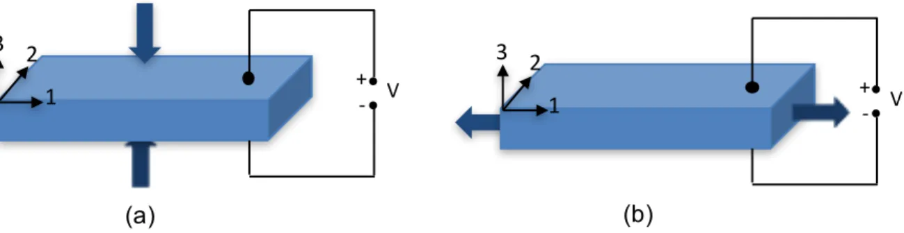
The 6 different stresses generate 3 axial electrical displacements on the unit cell and 5 different piezoelectric coefficients. Theses piezoelectric coefficients represents different types of piezoelectric coupling mode [32], among which the researchers are mostly interested in d33 and d31 representing the compression and stretching of a piezoelectric material, respectively. This is because the highest amount of power can be generated from these two modes [34]. The d33 coupling mode is known as the longitudinal coefficient in which the force is applied along the poling field direction. Examples include the compression of a piezoelectric material that is poled on its top and bottom surface. The transverse coefficient (d31) represents a coupling mode in which the stress is applied in the direction perpendicular to the poling field to induce an electrical polarization perpendicular to the applied stress. A bending beam poled on its top and bottom surfaces is an example of d31 coefficient [34]. An illustration of both modes is shown in Figure 2.2. The direct piezoelectric co-efficient dij is defined as [15]-
d<= = δD> δS?= δQ> & δF? & =δQ> δF? (2-6)
where, D is the electrical displacement or charge density (=Q/A), S is the applied mechanical stress (= F/A), Q is the accumulated charge and A is the sample area.
Figure 2.2: Schematic of the transduction mode of piezoelectric materials. (a) 33 mode and (b) -31 mode.
Typical Piezoelectric Materials
2.3.1 Crystal- Rochelle Salt
The concept of piezoelectricity and ferroelectricity was first discovered in Rochelle salt, NaKC4H4O6.4H2O and it remained for a long time the only known ferroelectrics [35]. It has a complex crystalline structure : orthorhombic in paraelectric phase and monoclinic in ferroelectric phase. It only exhibits ferroelectric behavior between 255 and 297 K [36]. Its density is about 1.77 g/cm3 with a melting point around 75 °C. In spite of its poor working temperature, Rochelle salt is used in multiple applications (acoustics) because of its very high piezoelectric coefficients [30]. Santos et al. [36] reported the values of d21 = 700 pC/N, d22 = 2200 pC/N, d23 = 2100 pC/N and d25 = 37 pC/N as determined by x-ray multiple diffraction.
2.3.2 Ceramic - Lead Zirconate Titanate (PZT)
PZT (Pb(ZrxTi1-x)O3) is considered as the pioneer material in evolving the piezoelectric effect from a laboratory curiosity to multimillion dollar industrial applications including underwater transducers and medical devices because of its strong piezoelectric coefficients. It is a perovskite crystal structure consisting of a small tetravalent metal ion (titanium or zirconium) in a lattice of large divalent metal ions (lead). With 54% zirconate and 46% titanate, piezoelectric d33 coefficients up to 600 pC/N have been reported [30].
3 2 1 +- V (a) 3 2 1 +- V (b)
Beside these typical materials, ceramic materials such as barium titanate (BaTiO3) and zinc oxide (ZnO) are also used in piezoelectric applications. However, these ceramic based transducers are brittle, non-flexible, hazardous and difficult to manufacture in large quantity [2]. Since in wearable electronic devices, challenges include limited space, shape and geometry, these ceramic based materials are not a suitable choice. However, the piezoelectric effect can be found in polymeric materials and they are an excellent choices for such wearable electronics.
Ferroelectric Polymer- b-Polyvinylidene Fluoride (b-PVDF)
Among the piezoelectric polymers, PVDF has the best inclusive electroactive properties and therefore, is the polymer of choice for a vast majority of applications [37]. It is a semicrystalline polymer with an amorphous density of 1.74 g/cm3 and a crystalline density of 2.00 g/cm3 at room temperature. It has a melting point of 160-165 °C and a glass transition temperature of about -35 °C. The PVDF unit cell contains two hydrogen atoms and two fluorine atoms as shown in Figure 2.3.
Figure 2.3: PVDF unit cell (-CH2-CF2), reprinted from [30].
Based on its chain conformation, PVDF can exhibit five different crystalline phases : all-trans (TTT) planar zigzag conformation for the b phase, TGTG' (trans-gauche-trans-gauche) for the a and d phases and T3GT3G' for the g and e phases [37, 38]. From a practical point of view,the a, b and g phases are the most important and commonly found in PVDF. In general, PVDF has strong electrical dipole moment in the monomer unit because of the higher fluorine atoms electronegativity compared to hydrogen and carbon atoms. Therefore, each polymer chain exhibits a dipole moment perpendicular to its axis. The most stable is the a phase because of the antiparallel packing of the dipoles within the unit cell which is non-polar and has low permittivity. On the other hand, the b phase has a crystal structure with fluorine atoms on one side and hydrogen atoms on
the other side of the polymer chain. Therefore, the dipole moment (8´10-30 Cm) is the highest in this crystalline form compared to the other phases because of its parallel dipoles packing [37-39]. The g phase is also polar and active but, unlike the b phase, it has a g-gauche bond at every fourth C-C repeating unit resulting in a weaker dipole moment compared to the b phase [40]. Figure 2.4 presents the chain conformation for these phases.
Figure 2.4: Schematic of the chain conformation of PVDF, reprinted form [37].
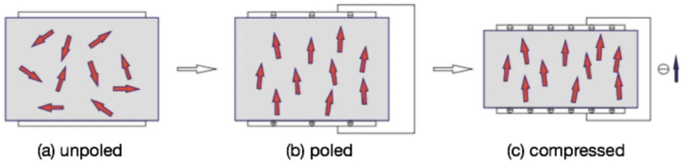
The piezoelectricity in b-PVDF arises from the electronegativity difference between the fluorine and hydrogen atoms in the molecular chain where the fluorine atoms pull away the shared electron from the hydrogen atom because of its stronger electron affinity. On the other hand, the b phase has a net dipole moment because it is randomly oriented in the film leading to a zero net polarization as shown in Figure 2.5 (a). The crystallites become oriented in response to an applied electrical field and exhibit net polarization even after its removal of the electric field as shown in Figure 2.5 (b). The volume polarization (or surface charge density, P) is given by :
P = @μA cosθ , μ = q×l (2-7) where N is the amount of dipoles within a volume V, µ is the dipole moment (a product of the charge q and the distance l between the charges), and q is the angle between the dipole moment and the polarization direction. The piezoelectricity originates from the volume change in response to the applied force. Under the applied compressive force both the volume V and the distance l
decrease. Since l is in the nanometer scale, its change can be neglected and thus the dipole density can be considered constant. Therefore, the overall volume polarization increases leading to improved compensating charges. Thus a flow of charge occurs in the direction shown in Figure 2.5 (c).
Figure 2.5: Illustration of the evolution of the piezoelectric effect from molecular dipoles in PVDF. (a) molecular dipoles oriented randomly before poling, (b) preferential alignment of the dipoles due to poling, and (c) increased polarization due to decreased thickness, reprinted from [30].
2.4.1 Formation of b-PVDF
Because of the growing interest in b-PVDF, several methods have been proposed and investigated to enhance the amount of b phase : solvent casting [41, 42], mechanical stretching [43], adding a PVDF copolymer [44-46] and nanofiller addition [8, 12, 47-50] as well as their combination.
Solution or solvent casting is one of the most commonly used methods because it is easy to carry out with a yields close to 100% b phase. However, it requires toxic or hazardous solvents like dimethylformamide (DMF) or chloroform [41]. Also, keeping the temperature below 70 °C during evaporation is crucial to maximize the amount of b phase produced since temperatures above 70 °C lead to a mixture of a a and b phases [51, 52]. Moreover, solution casting is not a suitable method for mass production which is a major drawback from an industrial point of view. Therefore, melt mixing like extrusion and injection molding is more acceptable in terms of large scale production.
In contrast to solvent casting, mechanical stretching of melt molded films is considered to be an easier way to obtain b-PVDF. In this process, mechanical stress applied to a PVDF film
resulting in polymer chains orientation with an all-trans planar zigzag (TTT) conformation. During stretching, molecular dipoles orient themselves perpendicular to applied stress direction [53]. Sencadas et al. [54] reported the presence of ~80%(maximum) β phase in PVDF at a temperature of 80°C and a stretching ratio (R) of 5. They also showed that increasing the temperature beyond 80°C significantly deteriorates the β phase formation. Salimi and Yousefi [53] found similar results of maximum β phase of around 75% at a stretching temperature of 75°C and a stretching ratio (R) between 4.5 and 5. They reported that the amount of β phase is more influenced by the stretching ratio than the stretching temperature. Wang et al. [55] found that electrical poling under a strong field could further increase the amount of b-PVDF.
As an attempt to further improve the PVDF properties to meet the increasing demand for modern technological applications, copolymers of PVDF have been introduced and investigated. Poly (vinylidene fluoride-trifluoroethylene) or P(VDF-TrFE) is one of the most popular copolymers where the TrFE monomer with its large steric hindrance forces the polymer to rearrange in an all-trans conformation (TTT) leading to the piezoelectric β phase regardless of the processing techniques: melt or solution casting [1, 37]. The favorable composition for maximum b phase is reported to be 50-80% VDF [56], with a corresponding maximum d33 of 38 pC/N. The copolymer of poly(vinylidene fluoride-chloride trifluoride ethylene) or P(VDF-CTFE) is another promising material for piezoelectric applications whose final properties depend on the amount of CTFE [57]. Addition of bulky CTFE makes the polymer structure loose and makes it easier for the molecular dipoles to rotate under an external electric field. A d33 coefficient of up to 140 pC/N has been reported [46], which is much higher than PVDF alone (up to 34 pC/N) [58].
The above-mentioned methods to produce the β phase are prone to create structural defects or microstructural restriction which may impede different applications [37, 59]. Hence, alternative methods have been investigated to meet specific technical demands. So, methods of obtaining the β phase by adding different types of fillers such as ferrite [60], organoclay [8, 10, 48, 49, 61], BaTiO3 [62], palladium [63], gold [64], and silver [63] are discussed next.
Figure 2.6: Mechanism of PVDF chain conformation change to TTT (b phase) in presence of (a) surface modified ferrite nanoparticle, reprinted from [65] and (b) montmorillonite clay, reprinted from [14].
Although the nucleation mechanism varies from filler to filler, the main driving force for the nucleation of the electroactive phase has been revealed to some extent for various fillers. By varying the surface charge and amount of the fillers, it was found that up to 90% β phase is possible to obtain by adding ferrite nanoparticles [60]. The nucleation of the β phase in such nanocomposites prepared by melt processing has been attributed to the interaction between the positively charged CH2 groups of PVDF and the negatively charged filler particles as shown in Figure 2.6(a). The d33 obtained was up to 33 pC/N in such nanocomposites. Another way to improve the piezoelectric properties of PVDF is adding piezoelectric fillers such as PZT and BaTiO3. The goal is to incorporate the high piezoelectric properties of these fillers in the PVDF matrix. For instance, Ye et al. [62] reported that up to 80% β-PVDF can be nucleated by adding BaTiO3 ceramic filler in PVDF by melt processing depending on the filler size and regardless of the amount of filler. However, the biggest drawbacks of these fillers include cost-intensive and difficulty to manufacture at industrial scales. Therefore, researchers have been inclined to use cheaper and more available fillers such as organoclay serving the purpose of polymer chain conformation in a similar mechanism as ferrite nanoparticles in Figure 2.6(b). Nucleation of the β phase using organically modified nanoclays in melt processed PVDF was first reported by Priya and Jog [8, 10, 49]. Similarly, Sadeghi et al. [61] reported the presence of the polar β phase in melt extruded PVDF/organoclay composites prepared using a twin-screw extruder.
Along with numerous other advantages, the increased interfacial area between the filler and the polymer in nanocomposites is a particularly interesting one. A nanofiller such as TiO2 has been reported by Nelson et al. [66] to modify the dielectric behavior of the polymer matrix. Interestingly, they found that micro-sized filler is more efficient in increasing the dielectric constant of the polymer because of its higher interfacial polarization compared to nanofillers. This arise from the fact that micro-fillers do not conform to the polymer chain length and enhance the occurrence of Maxwell-Wagner-Sillars (MWS) type of interfacial polarization arising from the difference of dielectric constant between the polymer and filler. Therefore, investigation of micro-sized filler or the combination of the piezoelectric properties of PVDF could be of interest.
Ferroelectret
An electret is a dielectric material consisting of quasi-permanent electrical charges. The charge is defined as “quasi-permanent” because the time constant characteristics of the charge decay is way much longer than the actual time period over which the studies are carried on these electrets.
Morphologically, a ferroelectret is a cellular polymer film with internally charged cells or voids exhibiting piezoelectric properties as shown in Figure 2.7. Sessler and his team [67] were the first to invent such a polymer structure during developing a charged polymer to be used as a microphone in 1962 and they named such polymer as ‘space charge electret’. However, it was not until the late 1980s that researchers accepted this concept and started investigating such systems for their piezoelectric properties [68].
The idea of piezoelectricity in ferroelectrets is illustrated in Figure 2.7. Starting with the polymer film with closed internal voids, the film can be a single layer or multi-layer with a thickness from 20 to 200 µm. The voids are usually lens-shaped but it could also be square or rectangular with a typical dimension of less than a dozen micrometer in the thickness direction and up to few dozens of micrometer in the longitudinal direction. Upon electrical charging, the gas inside the voids breaks down and accumulates on the internal surface of the voids. The piezoelectricity in these films arises from the macroscopic dipoles created from the separated positive and negative charges on the upper and lower surfaces of the voids (Figure 2.7a). The corresponding dipole moment (µ) is defined as:
µ = q ´ l (2-8) where, q is the amount of charge and l is the dipole distance (void height).
Figure 2.7: Schematic presentation of a ferroelectret. (a) macroscopic dipoles are formed in the voids at the gas/polymer interface after charging and (b) under mechanical stress, change in dipole moment causes the flow of charges, reprinted from [30].
Upon metallization, compensating charges are seen on the electrodes with the polarity opposite of the polarity of the dipoles on that side of the voids as shown in Figure 2.7(a). In this case, under an applied mechanical stress, the ferroelectret volume decreases which is more prominent than that for ferroelectric polymers (b-PVDF) because of the higher compressibility of the voids than the polymer bulk. As a result, the dipole moment (µ) decreases due to the decrease of the dipole distance l (Equation 2-8). On the other hand, the dipole density increases due to the decrease of the whole film volume. However, the extent of the dipole moment reduction is more pronounced than the increase of dipole density [30]. Therefore, the amount of compensating charges on the metal electrode decreases and flow of charges occurs as displayed in Figure 2.7(b).
2.5.1 Piezoelectric Coefficient of Ferroelectret
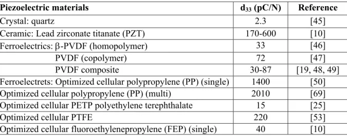
The piezoelectric coefficient of ferroelectrets is measured using the same principles as ferroelectrics described in section 2.2. Table 2.1 gives the typical d33 coefficient for various piezoelectric systems. Apart from the other advantages of ferroelectrets, their excellent piezoelectric d33 coefficient compared to traditional piezoelectric materials is the superior one. Despite superior piezoelectric response (d33 up to 600 pC/N), ceramics do not have the advantages
of polymers such as lightweight, easy formability, environment friendliness, etc. However, ferroelectric b-PVDF can only exhibit around hundred pC/N of d33 value in the form of a copolymer and composites. Ferroelectrets (PP) show a large d33 coefficient up to 2000 pC/N as shown in the Table 2.1, which is an added advantage for applications based on the thickness direction. Usually the piezoelectric properties of ferroelectrets are assessed by the d33 coefficient.
Table 2.1: Comparison of the piezoelectric d33 coefficients for common piezoelectric materials.
Piezoelectric materials d33 (pC/N) Reference
Crystal: quartz 2.3 [45]
Ceramic: Lead zirconate titanate (PZT) 170-600 [10]
Ferroelectrics: b-PVDF (homopolymer) 33 [46]
PVDF (copolymer) 72 [47]
PVDF composite 30-87 [19, 48, 49]
Ferroelectrets: Optimized cellular polypropylene (PP) (single) 1400 [50]
Optimized cellular polypropylene (PP) (multi) 2010 [69]
Optimized cellular PETP polyethylene terephthalate 15 [25]
Optimized cellular PTFE 220 [53]
Optimized cellular fluoroethylenepropylene (FEP) (single) 40 [10]
Since the piezoelectric activity (d33 coefficient) of polymer films originates from its change in thickness under an applied mechanical stress, the sample compressibility is critical in achieving the maximum piezoelectric response. Therefore, the compressibility, and thus the piezoelectricity, of a polymer foam strongly depends on the cellular structure morphology, its elastic stiffness and also on proper charging conditions. A controlled increase of the void thickness and then proper charging can lead to higher piezoelectric response.
2.5.2 Typical Ferroelectret Materials
2.5.2.1 Polypropylene (PP)
Polypropylene (PP) is a semicrystalline thermoelastic polymer used in a variety of applications like food packaging, automotive industry and medical instruments. Addition polymerization of the monomer propylene yields polypropylene which is chemically resistant (various acids, bases and solvents). The crystalline density of PP is 0.95 g/cm3 while the amorphous density is 0.85 g/cm3. The melting point ranges between 167 and 173 °C.
So far, PP foam is the most commonly used and scientifically investigated ferroelectret because of its availability, cost-effectiveness and ease of manufacturing. PP ferroelectret exhibits very high piezoelectric response, up to 1000 pC/N for a single layer [70], but values up to 2000 pC/N for a multilayer system have been reported [71]. However, one major disadvantage of these ferroelectrets is their very poor charge stability above 60 °C.
2.5.2.2 Polyethylene Terephthalate (PETP)
Polyethylene terephthalate (PETP) is a thermoplastic polymer synthesized by the transesterification reaction between ethylene glycol and dimethyl terephthalate. Its crystal density is 1.37 g/cm3 with a glass transition and melting temperatures of 75 and 260 °C, respectively.
Wegener et al. [25] reported the successful foaming of PETP using supercritical CO2. They also showed that foamed and stretched PETP films could exhibit a d33 of up to 20 pC/N after proper charging. Also, PETP films with density higher than 1 g/cm3 did not show any piezoelectric response. Later, they found that through optimized adjustment of the cellular structure, the voided-stretched films via inflation had d33 coefficients up to 470 pC/N could be obtained [27].
2.5.2.3 Fluoroethylene Propylene (FEP) and Polytetrafluoroethylene (PTFE)
Fluoroethylene propylene (FEP) is a copolymer of hexafluoropropylene (HFP) and tetrafluoroethylene (TFE) with an asymmetrical molecular structure. Unlike FEP, PTFE has a symmetrical structure and is synthesized from the free radical vinyl polymerization of the tetrafluoroethylene monomer. The PTFE chain contains –CF2 groups for every 180° turn in a twisting helix form. FEP has a similar molecular structure as PTFE except that a fluorine atom on each repeating unit is replaced with a perfluromethyl group, –CF3. Both PTFE and FEP were invented by DupontÒ and are available on the market by the brand name of TeflonÒ-PTFE and TeflonÒ-FEP [30]. The chemical structures of both PTFE and FEP are shown in Figure 2.8.
Figure 2.8: Chemical structures of (a) PTFE and (b) FEP.
PTFE and FEP have excellent physical, chemical and electrical properties. In general, PTFE has the highest thermal stability due to its regular packing of –CF2 crystalline unit driven by the mutual repulsion of adjacent fluorine atoms. Because of its extremely high molecular weight and consequently virtually infinite melt viscosity, PTFE is not melt-processable. Because of its fibrillar structure, it is not even suitable as ferroelectret. On the other hand, the bulky side group -CF3 in FEP disturbs the crystalline packing of the main chain and increases the amorphous fraction. Additionally, -CF3 group can be considered as defects in the crystallites. Therefore, FEP has a lower melting point than PTFE and is melt processable using conventional methods. Table 2.2 summarizes the useful properties of FEP and PTFE.
Table 2.2: Properties of PTFE and FEP [10].
Properties PTFE FEP
Density (kg/m3) 2200 2150
Elastic modulus (MPa) 500 480
Tensile strength (MPa) 23 23
Elongation at break (%) 250 325
Melting point (°C) 327 260
Maximum operating temperature (°C) 260 204
Dielectric constant at 1 MHz 2.1 2.1
2.5.3 Ferroelectret Formation
A lot of work has been devoted to cellular polymer systems to obtain an optimized piezoelectric response. In this regard, the formation of a cellular electret using fillers requires the following steps : (a) formation of voids by stretching the films filled with micron size particles or
by physical foaming, (b) improving the void geometry via gas inflation and heat treatment, and (c) formation of dipoles inside the voids by electrical charging and their stabilization. The process is schematically presented in Figure 2.9.
Figure 2.9: Schematic presentation of the fabrication process of ferroelectret using filler particles, reprinted from [2].
2.5.3.1 Cellular Structure Formation via Stretching or Foaming
There are few main routes to form voids in polymer systems. One of them involves modified extrusion process where gas injection into the molten polymer results in spherical voids. The resulting film is then reheated and biaxially stretched to reshape the spherical voids into lens-shape. The process was first introduced in the late 1980s for PP, but one of the main drawbacks of this technique is precise control of the blowing gas [30]. Therefore, another technique was proposed and investigated in the late 1990s by Raukola and Paajanen [21, 22, 69] where micron sized inorganic fillers such as titanium dioxide and calcium carbonate were melt mixed with PP via
extrusion. The mixture was extruded into films which was then stretched either uniaxially or biaxially using various stretching parameters including drawing ratio, temperature and others. During stretching, voids are formed around the filler particles through interfacial delamination of the partially molten polymer and the filler particles. A similar technique was successfully applied to cyclo-olefin polymers [24]. Since the resulting cellular structure is strongly dependent on the melt viscosity, fluoropolymers such as FEP and PTFE are not suitable for this technique because of their higher melt viscosity [30]. Another commonly used technique involves void formation by penetration of supercritical CO2 inside the polymer film under high pressure (up to 150 bar) followed by a heat treatment above 31 °C (Tc of CO2) of the CO2 saturated samples to transform CO2 into a gaseous state inside the films. PP [72], PETP [27] and FEP [28] have been investigated using these physical foaming processes. Sometimes, filler addition in the polymer matrix was made where the fillers acted as void nucleation sites [72]. Often, the void formation step is followed by high pressure gas inflation to adjust the void geometry as described in the next section.
2.5.3.2 Gas Diffusion Expansion (GDE) or Inflation
Stiffness, which is inversely related to the piezoelectric response of the polymer [73], is highly dependent on the size, shape and amount of voids of the cellular structure. There is a typical inversely-U shaped behavior as shown in Figure 2.10 (a-c). Films with small amount of voids with limited thickness (or flat) have relatively higher stiffness and therefore exhibit only low piezoelectricity (condition a). However, the controlled expansion of the void thickness by gas treatment lowers the overall film stiffness and increases the piezoelectric coefficient until a highly compressible, lens-shaped cellular structure is obtained (condition b). With continuous gas treatment, the lens-shaped, highly compressible voids in the film become more spherical in shape (with very low compressibility) leading to a strong stiffness increase. The increased stiffness ultimately results in a corresponding decrease in the piezoelectric response [17, 25]. Therefore, to adjust the cellular morphology in terms of amount of voids, void size, shape and aspect ratio inside the polymer films, gas diffusion expansion (GDE) or inflation treatment is performed. The overall dependence of the elastic stiffness, cellular morphology and piezoelectric response (Figure 2.10) has also been confirmed for PP foams via numerical simulations [74].
Figure 2.10: Schematic presentation of the correlation between the piezoelectric activity and elastic stiffness of a cellular film as a function of sample density and cellular morphology, reprinted from [26].
In a typical inflation treatment, the stretched or foamed polymer films are subjected to high pressure treatment for a certain period of time to ensure the saturation of voids with the high pressure gas. Once the applied pressure is reduced to atmospheric, the voids inside the film expands and the overall film thickness increases. If these films are left at rest, they return to their initial thickness in few hours. However, an elevated temperature treatment can stabilize the cellular structure and help retaining the increased sample thickness by increasing the crystallinity level and stiffening the foamed film to some extent [17, 75]. The temperature treatment could be done simultaneously or after the pressure treatment.
Furthermore, the way of applying pressure and heat treatment during inflation plays an important role on the ultimate film morphology. In an inflation experiment, Qaiss et al. [76] reported that an abrupt increase of pressure to higher value, 5 MPa for example, does not allow a progressive diffusion of the gases into the various cavities of the stretched PP-CaCO3 films. Rather,
such high pressure can collapse part of the voids due to a high compression effect related to the highly pressurized advancing gas. They found that pressure treatment in a stepwise manner at
higher temperature (close to the melting PP temperature) could create a progressive path for gas diffusion and push the inflation gas even in the small voids as well as preventing the collapse of cavities [76]. Mohebbi et al. [72] obtained similar results for PP foams prepared using supercritical CO2. In a separate experiment, Wegener et al. [18] performed an inflation experiment on foamed
PP where the pressure was applied from 0.2 MPa to 5 MPa followed by a heat treatment from 60 to 160 °C. They found that the inflation level saturates at a pressure around 5 MPa followed by a heat treatment at a temperature above 100 °C. They reported a 165% improvement in sample thickness over the non-inflated sample with an evenly distributed cellular structure (Figure 2.11). In a similar experiment, Sborikas et al. [17] obtained a maximum thickness increase of 257% for PP foam with an inflation pressure of 5 MPa and at a heat treatment temperature of 120 °C. However, Zhang et al. [70] suggested an additional inflation step followed by corona charging and metallization. They found that the obtained cellular structure after the first expansion of the PP foams at 2.5 MPa and an annealing treatment at 100 °C returned to its initial thickness after metallization. But a higher inflation level is obtained after the second expansion and after metallization at an annealing temperature of 45 °C with a stable cellular structure and reduced density.
Figure 2.11: Change in thickness and density of cellular PP film as a function of heat treatment temperature after inflation at 50 bar in N2 gas, reprinted from [17].
![Figure 2.4: Schematic of the chain conformation of PVDF, reprinted form [37].](https://thumb-eu.123doks.com/thumbv2/123doknet/2333519.32226/29.918.213.711.306.573/figure-schematic-chain-conformation-pvdf-reprinted-form.webp)
![Table 2.2: Properties of PTFE and FEP [10].](https://thumb-eu.123doks.com/thumbv2/123doknet/2333519.32226/37.918.202.724.695.892/table-properties-ptfe-fep.webp)
![Figure 2.9: Schematic presentation of the fabrication process of ferroelectret using filler particles, reprinted from [2]](https://thumb-eu.123doks.com/thumbv2/123doknet/2333519.32226/38.918.138.785.227.709/figure-schematic-presentation-fabrication-process-ferroelectret-particles-reprinted.webp)
![Figure 2.10: Schematic presentation of the correlation between the piezoelectric activity and elastic stiffness of a cellular film as a function of sample density and cellular morphology, reprinted from [26]](https://thumb-eu.123doks.com/thumbv2/123doknet/2333519.32226/40.918.285.688.110.502/schematic-presentation-correlation-piezoelectric-stiffness-cellular-morphology-reprinted.webp)
![Figure 2.13: Isothermal d33 decay curve of cellular PP and porous PTFE aged at 80 °C, reprinted from [87]](https://thumb-eu.123doks.com/thumbv2/123doknet/2333519.32226/45.918.226.697.316.676/figure-isothermal-decay-curve-cellular-porous-ptfe-reprinted.webp)