UNIVERSITÉ DE MONTRÉAL
EMERGING MICROSTRUCTURED FIBERS FOR LINEAR AND
NONLINEAR OPTICAL APPLICATIONS IN THE MID-INFRARED AND
TERAHERTZ SPECTRUM
BORA UNG
DÉPARTEMENT DE GÉNIE PHYSIQUE ÉCOLE POLYTECHNIQUE DE MONTRÉAL
THÈSE PRÉSENTÉE EN VUE DE L’OBTENTION DU DIPLÔME DE PHILOSOPHIAE DOCTOR
(GÉNIE PHYSIQUE) MAI 2012
UNIVERSITÉ DE MONTRÉAL
ÉCOLE POLYTECHNIQUE DE MONTRÉAL
Cette thèse intitulée :
EMERGING MICROSTRUCTURED FIBERS FOR LINEAR AND NONLINEAR OPTICAL APPLICATIONS IN THE MID-INFRARED AND TERAHERTZ SPECTRUM
présentée par : UNG Bora
en vue de l’obtention du diplôme de : Philosophiæ Doctor a été dûment accepté par le jury d’examen constitué de : M. MEUNIER Michel, Ph.D, président
M. SKOROBOGATIY Maksim A., Ph.D, membre et directeur de recherche M. AZAÑA José, Ph.D, membre
M. PICHÉ Michel, Ph.D, membre
DÉDICACE
REMERCIEMENTS
J'aimerais tout d'abord remercier mon directeur de thèse Maksim Skorobogatiy qui m'a offert une place au sein d'une équipe de recherche dynamique et m'a poussé à dépasser mes limites.
Aux cotés de tout théoricien se tiennent plusieurs collègues beaucoup plus habiles dans le labo que ce dernier: merci infiniment à Alexandre Dupuis, Anna Mazhorova, Mathieu Rozé, et Hang Qu, ainsi qu'au technicien Francis Boismenu. Merci aussi à Andrey Markov pour son aide avec certaines simulations numériques. Je remercie pour leur aide et les nombreuses interactions constructives mes collègues: Frédéric Désévédavy, Stephan Gorgutsa, Bertrand Gauvreau, Alireza Hassani, Ning Guo, Niyaz Madhar, Yang Liu et Imran Syed. Je remercie le Prof. Markus Walther de la Freiburg University qui nous a assisté dans la caractérisation par champ proche térahertz de certaines fibres optiques, et dans l'interprétation de ces données.
Je remercie également mes amis du Groupe des Couches Minces pour leurs remarques instructives, scientifiques ou amusantes qui ont ponctuées nos discussions du midi.
Une mention très spéciale à mon épouse Marie-Hélène pour sa patience et son support infaillible durant ces belles années, ainsi qu'à mes parents et frères, et ma nouvelle famille Thibault. Vos mots d'encouragement ont été précieux, je vous en suis sincèrement reconnaissant.
Grâce à vous tous, je ressors de mon expérience doctorale bien vivant, plus sage et mature, et plus curieux qu'auparavant.
RÉSUMÉ
Les régions spectrales des ondes térahertz (THz) et de l'infrarouge moyen (mIR) représentent les frontières immédiates nous séparant du but d'exploiter le spectre électromagnétique dans son intégralité pour les applications technologiques du futur.
La bande spectrale de l'infrarouge moyen couvre les longueurs d’ondes entre 2 et 20 microns du spectre infrarouge. Diverses applications tirant profit du mIR sont envisagées dans de nombreux domaines d intér ts tels: spectroscopie imagerie infrarouge chirurgie laser et bio-diagnostic Malgré les nombreux avantages immédiats pouvant tre tirés des applications du spectre mIR, sa pleine exploitation demeure ce jour limitée en raison d’une part par le manque de sources laser mIR couvrant une large portion de ce domaine spectral En effet la majorité des sources cohérentes mIR actuellement disponibles oscillateurs paramétriques optiques lasers cascades quantiques lasers électrons libres sont discr tes et restreignent ainsi les applications une seule longueur d’onde spécifique la fois. Il existe actuellement une forte demande au sein de l'industrie et la communauté scientifique pour la création d’une source lumineuse cohérente large bande spectrale émettant dans le mIR, et sous une forme compacte.
Le premier sujet de recherche de cette thèse se rapporte au design de nouvelles fibres hautement nonlinéaires (FHNL) pour leur utilisation dans la génération de lumière mIR (e.g. génération d'un supercontinuum), et au sein de dispositifs de conversion en longueurs d'onde mIR basés sur des effets optiques nonlinéaires. À cet effet, l'efficacité de génération/conversion de la lumière mIR dépend intimement du contrôle des propriétés optiques linéaires et nonlinéaires du guide d'onde employé dans le système. Au cours de mes travaux, j'ai étudié différents designs de guides d'ondes microstructurés (ou nanostructurés) hautement nonlinéaires et possédant un potentiel pour des applications à impact concret. Plus particulièrement, nous avons démontré deux nouveaux types de FHNL: la fibre optique nanostructurée hybride en chalcogénures-métal qui supporte un mode plasmonique permettant un confinement du champ à des dimensions profondément sous-longueur d'ondes, ainsi que la fibre microporeuse en verres de chalcogénures offrant des possibilités étendues pour le contrôle de la dispersion chromatique dans les fibres optiques nonlinéaires. Par ailleurs, des simulations numériques basées sur l'équation de Schrodinger nonlinéaire, et assumant cette dernière FHNL comme guide d'onde, ont été effectuées et ont démontré leur potentiel pour la génération d'un large supercontinuum mIR dans
une fibre microporeuse en chalcogénures excitée à de larges longueur d'ondes i e 10 5 μm) par des impulsions picosecondes.
De plus, une étude sur la fibre optique nanostructurée hybride chalcogénures-métal a démontré sa capacité à confiner un mode guidé à des dimensions sous-longueur d'ondes, en deçà des limites classiques de diffraction de la lumière. Cet exploit est rendu possible en tirant profit des plasmons polaritons de surface guidés par la matrice de nanofils métalliques insérés dans le coeur de la FHNL. Ce confinement modal sous-longueur d'onde se traduit par une exaltation considérable du coefficient nonlinéaire qui constitue la pi ce ma tresse dans la réalisation d une source mIR large bande fibre via la génération d'un supercontinuum, ainsi que pour la conception de composants photoniques intégrés hautement nonlinéaires.
D'autre part, les ondes térahertz (comprenant les longueurs d ondes entre 80 et 3000 μm) procurent une radiation à basse énergie non-ionisante et faiblement pénétrante, possédant un immense potentiel pour des applications en détection non-destructive et en imagerie dans plusieurs domaines dont la médecine et en défense. Toutefois, la majorité des matériaux testés à ce jour sont soit opaques ou très atténuants à l'intérieur du spectre THz. Par conséquent, un des défis technologiques important à l'heure actuelle en science du térahertz, consiste au développement de guides d'ondes THz à faibles pertes. Ce deuxième sujet de recherche fut exploré dans cette thèse: nous avons effectué le design, la fabrication et la caractérisation de plusieurs types de guides d'ondes THz basés sur des matériaux en polymères. Les résultats obtenus ont démontré un impact pratique dans l'acheminement efficace de signaux THz. A cet égard, notons que les fibres optiques à base de polymères offrent une plate-forme versatile pour le développement de guides d'ondes térahertz. Les principaux avantages des polymères inclus: l'abondance et le bas coût des différentes compositions chimiques offrant des pertes optiques relativement basses; la facilité à concevoir les préformes des fibres microstructurées via des techniques conventionnelles de moulage, fraisage et par empillement; et finalement, la simplicité et la commodité de la méthode de fabrication des fibres par étirage à des températures de mise en forme relativement basses.
Nous avons étudié les performances de fibres de Bragg à coeur creux fabriquées à partir d'une matrice de polymère dopée (à différents degrés de dopage) avec des microparticules de titane possédant un fort indice de réfraction et de fortes pertes optiques. Notre analyse a révélé
que les hautes pertes par absorption générées par une haute concentration de dopants peuvent effectivement annihiler le mécanisme de guidage par bande photonique interdite des fibres de Bragg. Nous en déduisons donc qu'un compromis entre le fort contraste d'indice de réfraction (le "bénéfice") et les fortes pertes optiques ("l'inconvénient") qui subsistent à hautes concentrations de dopants, est nécessaire. Cette découverte est particulièrement utile au design de composants THz basés sur le principe de bandes photoniques interdites et fabriqués avec des matériaux composites en polymères.
Plusieurs designs récents de guides d'ondes térahertz ont opté pour l'approche d'une réduction de la fraction de puissance guidée dans les sections de matériaux à grandes pertes, dans le but de mitiger les pertes de guidage des signaux THz. Toutefois, les champs hautement délocalisés qui émanent de la plupart de ces designs "poreux" entravent leur adoption en pratique. La raison étant qu'un champ modal délocalisé s'accompagne généralement d'une sensibilité modale accrue à toute perturbation dans le milieu ambiant, incluant la simple manipulation des fibres par un utilisateur. Une solution décrite dans cette thèse consiste en une fibre diélectrique à coeur suspendu, qui procure une propagation guidée dans un coeur complètement cloisonné à l'intérieur d'un tube de polymère ayant la double fonction d'isoler le mode guidé des perturbations externes, et de protéger la surface du coeur de l'accumulation de contaminants indésirables tels des poussières. Des mesures expérimentales du profil du mode de sortie, tirées d'imagerie THz par champ-proche (et confirmé avec des simulations par éléments finis), indiquent que la fibre diélectrique à coeur suspendu permet un guidage "monomode effectif" à l'intérieur de sa fenêtre de transmission principale. Grâce à la grande fraction de puissance guidée dans la section de gaine poreuse entourant le coeur suspendu, des pertes en propagation aussi basses que 0.02 cm-1 ont été mesurées expérimentalement avec une telle fibre fabriquée dans nos labs.
Finalement, les limites physiques et les seuils de performance des différents designs de fibres proposés pour le mIR et le THz sont discutés, et des directions de recherches futures sont suggérées afin de résoudre ou réduire certaines de ces limites, avec l'intention de faire progresser le savoir sur les sujets traités dans cette thèse.
ABSTRACT
The terahertz (THz) and middle-infrared spectrum (mIR) represent the next frontiers in the goal of harnessing the whole electromagnetic spectrum in future technological applications.
The middle-infrared spectral band covers the wavelengths between 2 and 20 microns in the infrared. A myriad of applications that take advantage of the mIR spectrum are envisioned in several fields of interest such as: spectroscopy, infrared imagery, laser surgery and bio-diagnostic. Despite the numerous immediate benefits that may be reaped from applications of mIR technology, its full exploitation remains limited by the lack of bright and coherent optical sources of mIR light. In fact, the majority of current mIR coherent sources (optical parametric oscillators, quantum cascade lasers, free electron lasers) are discrete and thus restrict applications to a single specific wavelength at a time. Thus there is presently a strong demand within the industrial and academic communities for the creation of a broad bandwidth coherent mIR light source in a compact form factor.
The first research topic of my thesis was to design novel highly-nonlinear fibers (HNLFs) to be used in mIR light generation (e.g. supercontinuum generation) and mIR wavelength conversion schemes based on nonlinear optical effects. The efficiency of mIR light generation/conversion depends intimately on the precise control of the linear and nonlinear optical properties of the waveguide used in the optical setup. During the course of this work, we investigated various designs of both microstructured and nanostructured highly-nonlinear waveguides with great potential for end-user applications. In particular, we demonstrated two novel types of HNLFs: the hybrid chalcogenide-metal nanostructured optical fiber that supports a plasmonic mode enabling deep-subwavelength field confinement capabilities, and the chalcogenide microporous fiber that provides extensive design freedom for engineering the chromatic dispersion of nonlinear fibers. Furthermore, simulations of the nonlinear Schrodinger equation, assuming the latter type of HLNF, were performed and showed the potential for generating a broad mIR supercontinuum inside a chalcogenide microporous fiber seeded at long wavelengths (i.e. 10.5 μm) using short picosecond pulses.
Furthermore, the study of the hybrid chalcogenide-metal nanostructured optical fiber demonstrated subwavelength-size optical mode confinement beyond the classical diffraction limit. This feat was made possible by harnessing surface plasmon polaritons guided by the
metallic nanowire arrays integrated within the core of the HNLF. This subwavelength-size modal confinement translates into an extremely large nonlinear optical enhancement that provides the key component towards the realisation of broadband mIR sources via supercontinuum generation, and highly-nonlinear and highly-integrated photonic components in general.
Terahertz waves (comprising wavelengths between 80 and 3000 μm), on the other hand, provide a low-energy, non-ionizing and slightly penetrating radiation with immense potential for non-destructive sensing and imaging applications in medicine and security, among others. However most materials are opaque or very absorbant in the THz range. Therefore an important technological challenge resides in guiding THz waves to a remote location with low signal losses. This second topic of research was studied in my thesis: we designed, fabricated and characterized various types of THz waveguides based on polymer materials, and which demonstrated a high practical impact for the efficient delivery of terahertz radiation. In this regard, polymer optical fibers provide a versatile platform for guiding THz radiation. The key benefits of this technology include: the abundance of the low-cost and relatively low-absorption-loss polymers; the ease of fiber preform fabrication by molding, drilling, stacking and the use of other standard polymer processing techniques; and finally the convenience of simple fabrication method by fiber drawing at relatively low-forming temperatures.
We studied the performance of hollow-core Bragg fibers fabricated using a host polymer matrix with varying doping levels of high-index and high-loss titania microparticles. Our analysis revealed that the large absorption losses induced by the high concentration of dopants can effectively destroy the photonic bandgap guiding mechanism of Bragg fibers such that an appropriate trade-off between the high-refractive-index contrast and the large associated material losses is necessary. This finding is relevant to the design of THz optical components based on polymeric composite materials.
Several recent designs of terahertz waveguides have taken the approach of reducing the fraction of guided optical power in lossy materials regions so as to minimize the modal propagation losses of the THz signal. However the highly-delocalized modal fields in many of these designs hinders their practical use for THz waveguiding, because of their significant modal sensibility to external perturbations like simple hand manipulation of the fiber. A solution was proposed in this thesis via the suspended core dielectric fiber which enables a fully-encapsulated
core-guided modal propagation inside an outer polymer tube cladding that provides protection against external pertubations and the accumulation of surface contaminants on the suspended core's surface. Experimental measurements of the output mode profiles, performed with THz near-field imaging (and confirmed by finite-element simulations), have indicated that the suspended core dielectric fiber guides in an effectively single-mode regime inside its main low-loss window. Owing to the large fraction of modal power that is guided in the holey cladding, experimental fiber propagation losses as low as 0.02 cm-1 have been demonstrated with the fabricated fiber.
Finally, the performance and physical limitations of the proposed designs of fibers for the mIR and THz spectrum are discussed, and potential future research directions are suggested to solve or alleviate some of these limitations and gain new grounds on the subjects covered therein.
TABLE OF CONTENTS
DÉDICACE ... III REMERCIEMENTS ... IV RÉSUMÉ ... V ABSTRACT ... VIII TABLE OF CONTENTS ... XI LIST OF FIGURES ... XIV LIST OF APPENDICES ... XXI LIST OF SYMBOLS AND ABBREVIATIONS ... XXIIINTRODUCTION ... 1
CHAPTER 1 : LITERATURE REVIEW ... 4
1.1 Nonlinear microstructured optical fibers for the middle-infrared ... 4
1.2 Microstructured optical fibers for terahertz waveguiding ... 14
CHAPTER 2 : EMERGING MICROSTRUCTURED CHALCOGENIDE FIBERS FOR LINEAR AND NONLINEAR OPTICAL APPLICATIONS IN THE MIDDLE-INFRARED SPECTRUM... ... 23
2.1 Chalcogenide microporous fibers for linear and nonlinear applications in the mid-infrared ... 24
2.1.1 Introduction ... 24
2.1.2 Optical properties of the chosen nonlinear glass ... 26
2.1.3 Geometry of proposed design ... 26
2.1.4 Results and discussion of the finite-element method simulations ... 28
2.1.5 Simulation of the nonlinear Schrodinger equation for pulse propagation in nonlinear optical media ... 32
2.1.6 Simulations of supercontinuum generation ... 34
2.1.7 Conclusions ... 36
2.2 Extreme nonlinear optical enhancement in chalcogenide glass fibers with deep-subwavelength metallic nanowires ... 37
2.2.1 Introduction ... 37
2.2.2 Motivations and geometry of proposed design ... 37
2.2.3 Simulations of the subwavelength field confinement and the extreme nonlinear optical enhancement ... 41
2.2.4 Characterization of the modal propagation losses and discussion ... 42
2.2.5 Conclusions ... 43
CHAPTER 3 : EMERGING MICROSTRUCTURED POLYMER FIBERS FOR TERAHERTZ WAVEGUIDING ... 45
3.1 High-refractive-index composite materials for terahertz waveguides: trade-off between index contrast and absorption loss ... 45
3.1.1 Introduction ... 45
3.1.2 Geometry of the hollow-core Bragg fibers ... 46
3.1.3 Optical characterization of the titania-doped polymer composites ... 47
3.1.4 Vectorial simulations of the modal properties in doped Bragg fibers ... 49
3.1.5 Discussion on the trade-off between index contrast and absorption losses in doped Bragg fibers ... 50
3.1.6 Conclusions ... 54
3.2 Suspended core subwavelength fibers: towards practical designs for low-loss terahertz guidance ... 55
3.2.1 Introduction ... 55
3.2.3 Optical characterization of the polyethylene polymer, and fabrication of the
suspended core dielectric fibers ... 56
3.2.4 Terahertz near-field imaging setup for the characterization of the modal properties in the suspended core dielectric fibers ... 57
3.2.5 Comparison between the experiments and simulations of the output modal field distributions ... 58
3.2.6 Fiber output transmission and propagation losses: results and discussions ... 63
3.2.7 Conclusions ... 68
CHAPTER 4 : GENERAL DISCUSSION, CONCLUSIONS AND PERSPECTIVES ... 69
4.1 Nonlinear emerging microstructured fibers for the middle-infrared ... 69
4.2 Emerging microstructured fibers for terahertz waveguiding ... 73
REFERENCES ... 78
LIST OF FIGURES
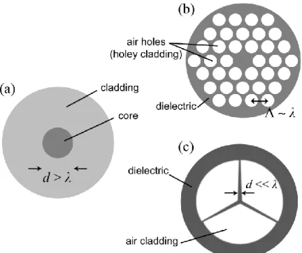
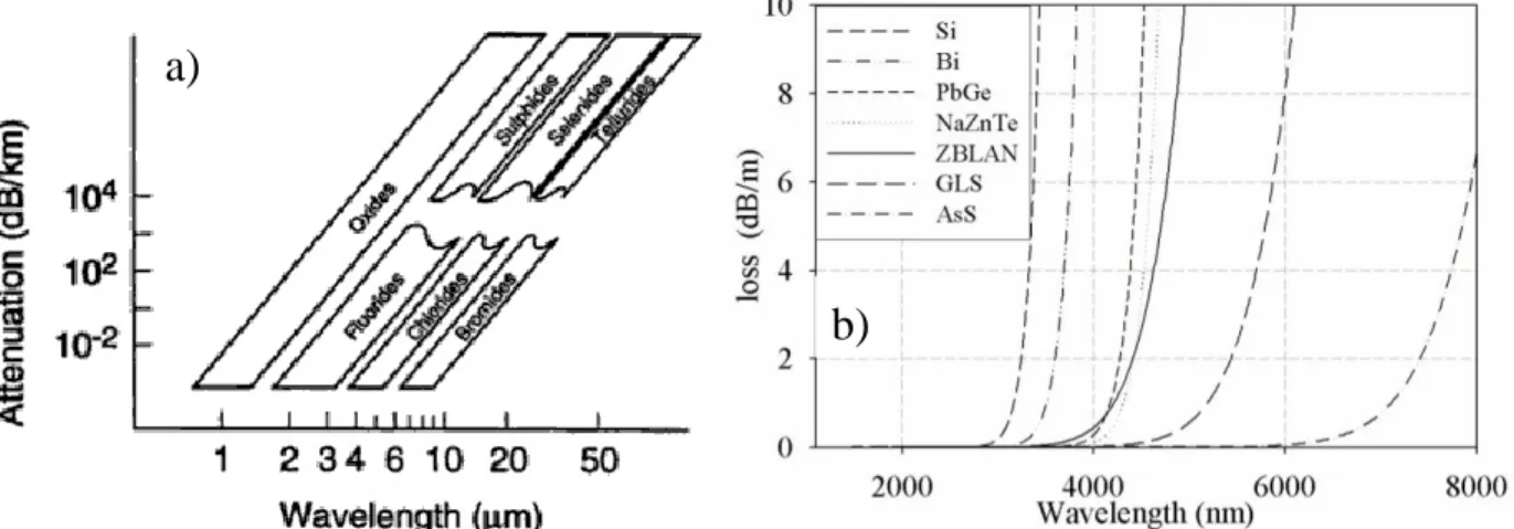
Figure 1.1 Cross-sections of (a) conventional step-index fiber (the core has a slightly higher refractive index than the cladding), and of two specific examples of emerging microstructured fibers: (b) a photonic crystal fiber, and (c) a suspended small core "wagon-wheel" fiber. ... 2 Figure 1.2 (a) Multiphonon absorption limits, and (b) absorption loss curves showing the
multiphonon edge for various types of glasses. Reproduced from [14] with permission of Taylor & Francis Group LLC; permission conveyed through Copyright Clearance Center Inc. ... 5 Figure 1.3 Variation of the group velocity chromatic dispersion (solid and long-dash lines) of
plane waves propagating in bulk fused silica (data extracted from Chapter 1.2.3 in [4]). ... 11 Figure 1.4 (a) Example of a typical open-cage fitted with a terahertz scanner for stand-off full-body THz imaging, and (b) false-color representation of the extracted THz signal absorption from a full-body THz scan. Images obtained from [116]. ... 15 Figure 1.5 (a) Refractive index and (b) bulk absorption coefficient in (cm−1) of common
polymers used in the fabrication of THz waveguides. Legend: low-density polyethylene (LDPE), cyclic olefin copolymer (TOPAS®), high-density polyethylene (HDPE), Poly-tetrafluoroethylene (PTFE) a.k.a Teflon®, polycarbonate (PC), polymethyl-methacrylate (PMMA), polyimide (Kapton®), polystyrene (PS), Polypropylene (PP). Data compiled from references [122-124]. ... 16 Figure 1.6 (a) Schematic of the cross-section of a porous fiber with N = 3 layers of holes. (b)
Fundamental HE11 mode Sz-profile at 1 THz frequency in a subwavelength porous core PE fiber (dfiber = 120 µm, dhole = 9 µm), and (c) in a subwavelength solid core PE fiber (dfiber = 120 µm). Calculations performed using the full-vector finite-element method. ... 17 Figure 1.7 (a) Schematic of hollow Bragg fiber with N = 5 bilayers of high-index layers (dark
fringes) and low-index layers (pale fringes). (b) Fabricated Bragg fiber with high-index TiO2 doped layers and low-index PE layers. (c) Fabricated Bragg fiber with high-index PE layers separated by PMMA particles from the low-index air layers. (d) Fundamental HE11 mode profile at 1 THz inside the TiO2-doped Bragg fiber of sub-figure (b) with dcore =6.63 mm, dH
=135 μm, and dL =100 μm. Sub-figures (b) and (c) are reprinted from [151] and [152] respectively, with permission from The Optical Society of America. ... 21 Figure 2.1 Total chromatic dispersion (D) in sulfide As2S3-glass suspended small-core fibers
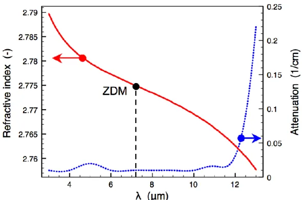
with varying core sizes. The strong anomalous waveguide dispersion (Dwvg) enables to partly compensate for the normal dispersion of the material (Dmat) thus allowing to blue-shift the zero-dispersion wavelength of the waveguide from that of the material dispersion. Reprinted from [93] with permission from The Optical Society of America. ... 25 Figure 2.2 Refractive index (solid red line) and absorption coefficient (dotted blue line) of bulk
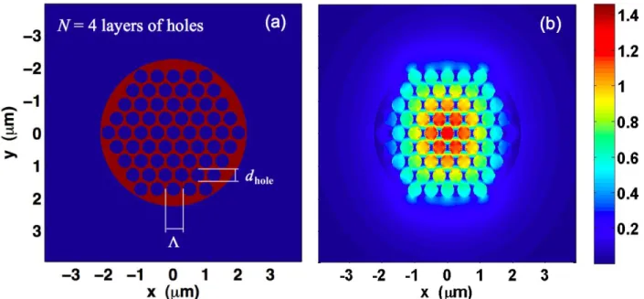
selenide (As2Se3) glass as a function of excitation wavelength. The material zero-dispersion wavelength ZDM is located at 7 225 μm Reprinted from [99] with permission from The Optical Society of America. ... 26 Figure 2.3 (a) Refractive index distribution (red: As2Se3-glass, blue: air) in a N=4 ( 0.50μm
dhole0.42μm) chalcogenide microporous fiber, and (b) Sz-power distribution (in a.u.) of the fundamental HE11 mode at the 10 5 μm input wavelength Reprinted from [99] with permission from The Optical Society of America. ... 27 Figure 2.4 (a) Cross-sectional density fm of solid material in N=4 layers microporous fiber and
(b) fraction of modal absorption fα over bulk As2Se3 absorption at λ=10 5 μm as a function of parameters Λ dhole). The dotted line identifies the regions of fα = 0.5 (Reprinted from [99]). ... 28 Figure 2.5 (a) Real effective refractive index and (b) effective mode area of the fundamental
mode in N = 4 layers As2Se3 microporous fiber at λ = 10 5 μm as a function of parameters Λ dhole). Reprinted from [99] with permission from The Optical Society of America. ... 29 Figure 2.6 (a) Dispersion parameter (D) and (b) dispersion slope (dD d) in N = 4 layers As2Se3 microporous fiber at λ = 10 5 μm as a function of parameters Λ dhole). Reprinted from [99]. ... 30 Figure 2.7 (a) Chromatic dispersion curves (ps (km nm) ) showing near-zero and flattened
dispersion at λ=10 5 μm for parameters (a) (Λ=0 50, dhole=0.38)μm, and (b) Λ=0 70,
dhole=0.62)μm. The blue curve plots the As2Se3-glass material dispersion. Reprinted from [99]. ... 30
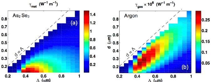
Figure 2.8 Contribution to the nonlinear parameter (W-1m-1) due to (a) As2Se3 glass, and (b) Argon gas-filled holes at λ=10 5 μm as a function of Λ dhole) for a N = 4 layers microporous fiber. Gas nonlinearities are multiplied by a factor 106, for scaling reasons. Reprinted from [99]. ... 31 Figure 2.9 (a) Raman response function hR(t) of bulk As2Se3 glass, and (b) the corresponding
Raman gain spectrum (gR()) measured at pump wavelength λ=1 54 μm. Adapted from [99]. ... 33 Figure 2.10 Output supercontinuum spectra calculated via SSFM in a microporous fiber with
parameters (Λ=0.40, dhole=0.24)μm, L=10 cm and for (a) E0=0.9 nJ fixed seed energy with varying FWHM pulse durations (0.1, 1, 10) ps, and (b) for fixed pulse duration TFWHM1 ps
and varying seed energies (0.2, 2.0, 5.0) nJ. The peak power (P1) of the first ejected fundamental soliton created by the fission of the Nsol-th order soliton, is shown alongside its corresponding curve. Reprinted from [99] with permission from The Optical Society of America. ... 35 Figure 2.11 Micrographs of the cross-sections of (a) a chalcogenide Te-As-Se glass photonic
crystal fiber with structural parameters (Λ=13.77, dhole=6.14)μm image adapted from [39]), and (b) a chalcogenide Sb20S65Ge15 glass photonic crystal fiber with structural parameters (Λ=11.1, dhole=4.7)μm (image adapted from [46]). We note the small empty interstices between the holes. Both images reprinted with permission from The Optical Society of America. ... 38 Figure 2.12 (a) Schematic of a gold bowtie nanoantenna on top of a transparent PMMA substrate
(black arrows denote fluorescent molecules in suspension). (b) Vectorial finite-difference time-domain calculation of the local intensity enhancement at λ=780 nm. Adapted by permission from Macmillan Publishers Ltd: Nature Photonics (Ref.[200]), copyright (2009). ... 38 Figure 2.13 (a) Triangular lattice configuration of overlapping rods and small interstices with (b)
a close-up view of the unit-cell geometry along with the relevant structural parameters. (c) Sz-power flux distribution of the fundamental plasmonic mode in the chalcometallic nanostructured fiber (rfiber = 0.450 μm, fδ = 0.03) at λ=3.0 μm, and (d) close-up view of a
bowtie pair of nanowires showing the enhanced local fields in a.u. (arrows denote the vector E-fields). Reprinted from [100] with permission from The Optical Society of America. ... 39 Figure 2.14 (a) Triangular lattice configuration of three tangent circular rods of identical radii
(rrod) and (b) a close-up view of the enclosed deltoid-shaped nanowire, along with the inscribed circle of radius (rdel). ... 40 Figure 2.15 (a) Optical nonlinearity (γ) and (b) effective mode area (Aeff) of a bare chalcogenide
nanowire and a hybrid chalco-metallic NOF at λ=3.0 μm as a function of the fiber radius. Reprinted from [100] with permission from The Optical Society of America. ... 41 Figure 2.16 (a) Real effective refractive index (neff) and (b) effective propagation length (Leff) of
a bare chalcogenide nanowire and a hybrid chalco-metallic nanofiber at λ=3.0 μm as a function of the fiber radius. Inset in (a): fraction of power guided inside metallic regions for the chalco-metallic fiber (solid curve) and inside chalcogenide glass, for the nanowire (dashed curve). The neff and Leff of a classical SPP on the gold–As2Se3 planar interface is also shown (green dot–dashed curve) for reference in (a) and (b) respectively. Reprinted from [100] with permission. ... 42 Figure 3.1 Hollow-core Bragg fiber with the reflector made of alternating hRI TiO2-doped PE
layers and low-index pure PE layers. (a) Structure with 14 bilayers used in the T-matrix calcula- tions. (b) Bragg fiber with five bilayers fabricated using a combination of film extrusion, hot pressing, and subsequent coiling. Reprinted from [151] with permission from The Optical Society of America. ... 46 Figure 3.2 Refractive index of a PE-based polymer compound as a function of weight
concentration of TiO2 particles: Bruggeman model fit (solid curve) [see Eq. (3.1)] and measurements at 1 THz frequency (circles). Inset: THz-TDS measurements of the refractive index for pure PE (dashed curve), 40 wt.% (dotted curve), and 80 wt.% (solid curve) TiO2 doping. Reprinted from [151] with permission from The Optical Society of America. ... 47 Figure 3.3 Power absorption loss of the doped PE-based polymer compound as a function of
frequency (THz) for various levels of TiO2 doping concentrations: 0 wt.% (pure PE), 40 wt.%, and 80 wt.%. Squares, circles, and triangles denote THz-TDS measurements, while the dashed, dotted and solid curves represent the corresponding polynomial fits [see Eq. (3.2)]. Reprinted from [151] with permission from The Optical Society of America. ... 48
Figure 3.4 Fundamental mode loss in doped-PE/PE hollow-core polymer Bragg fibers (14 bilayers) as a function of input frequency and for various levels of fractional nominal loss (floss) inside the dielectric layers. Inset: calculated fundamental mode power profile at 1 THz. Reprinted from [151] with permission from The Optical Society of America. ... 49 Figure 3.5 Fundamental mode loss (dB/m) as a function of TiO2 doping concentration of high-index layers and frequency, for an ideal Bragg fiber (five bilayers) whose reflector layer thicknesses are tuned to obey the quarter-wave condition near the center frequency 1 THz. Reprinted from [151] with permission from The Optical Society of America. ... 52 Figure 3.6 Fundamental mode loss (dB/m) in 80 wt.% doped Bragg fiber (five bilayers)
computed by the T-matrix method (dashed curve) with perfect circular symmetry, and via the FEM (dotted curve) with the spiral shape defect (shown inset). THz-TDS measurements of total attenuation (open circles), and theoretical calculations including coupling losses and intermodal interference effects (solid curve). Reprinted from [151] with permission from The Optical Society of America. ... 53 Figure 3.7 (a) Cross-section of the suspended solid core fiber (OD = 5.1 mm), and (b) close-up
view of the suspended solid core region (dcore 150 μm). (c) Cross-section of the suspended porous core fiber (OD = 3 mm), and (d) close-up view of the suspended large porous core (dcore = 900 μm). Reprinted from [139] with permission from The Optical Society of America. ... 55 Figure 3.8 (a) Refractive index and (b) bulk material losses of polyethylene (PE) in the
frequency range 0.10 – 1 THz as measured by THz-TDS. The inset picture in Fig.(a) shows the PE slab used for the measurements. Reprinted from [139] with permission from The Optical Society of America. ... 56 Figure 3.9 Schematic of the THz near-field microscopy setup used for fiber mode profiling. ... 58 Figure 3.10 Near-field microscopy images (top row) and corresponding simulations (bottom
row) of the output |Ex|-field profile of the suspended small solid core fiber at 0.16, 0.30 and 0.48 THz. Reprinted from [139] with permission from The Optical Society of America. .... 59
Figure 3.11 Near-field microscopy images (top row) and corresponding simulations (bottom row) of the output |Ex|-field profile of the suspended large porous core fiber at 0.10, 0.16 and 0.30 THz. Reprinted from [139] with permission from The Optical Society of America. .... 60 Figure 3.12 Gaussian beam waist parameter (σ) as a function of input wavelength, as measured
with the THz near-field microscopy setup (dots), and modeled by a linear fit (solid line). Reprinted from [139] with permission from The Optical Society of America. ... 62 Figure 3.13 Transmitted |Ex|-field as measured by the near-field THz-TDS probe between 0.01
and 0.80 THz for various lengths of (a) suspended small solid core fiber, and (b) suspended large porous core fiber. Corresponding numerical simulations of the amplitude transmission through the (c) suspended solid core fiber, and (d) the suspended porous core fiber. Reprinted from [139]. ... 64 Figure 3.14 (a) Power propagation losses (measured by the cutback method) of the suspended
solid core fiber, and of the (b) suspended porous core fiber, as a function of frequency. Dashed line corresponds to quadratic fit of the bulk material losses. Reprinted from [139] with permission from The Optical Society of America. ... 66 Figure 3.15 Near-field microscopy images of the output |Ex|-field profile at (a) 0.67 THz and (b)
0.72 THz, that indicate the presence of a higher-order guided mode in the suspended small solid core fiber. ... 67 Figure 4.1 Schematic of the tapering of a multimoded nonlinear optical fiber into a single-mode
fiber (along with enhanced optical nonlinearities inside the tapered section). ... 70 Figure 4.2 Finite element method simulations of optical heat generation at a silver nanowire
junction during the nanowelding process in the 2 nm gap between silver nanowires with a 100 nm diameter and circular cross-section. The illumination source is a plane wave with a wavelength of 800 nm, incident from the top and polarized perpendicular to the top nanowire. Reprinted by permission from Macmillan Publishers Ltd: Nature Materials (Ref.[227]), copyright (2012). ... 72
Figure B. 1 Convergence study for the fundamental mode guided in a specific microporous chalcogenide fiber geometry at 10.5 m and for polynomial order n2. FEM calculations conducted with RSoft FemSIM® software. ... 108 Figure B. 2 Triangular mesh generated by COMSOL® at different zoom scales, starting from
farthest (a) to closest (d), for modelling a hybrid chalco-metallic nanofiber [see Chapter 2.2]. ... 109 Figure B. 3 (a) Partial zoom image of the mesh generated by COMSOL® and (b) corresponding
partial image of the fundamental mode in the hybrid chalco-metallic nanofiber at 3.0 m and for polynomial order n3. ... 110
Figure C. 1 Schematic of the procedural implementation of the symmetrized split-step Fourier method. ... 112
Figure D. 1 Schematic of the cutback technique procedure for measuring the optical propagation losses in an optical fiber. ... 114
LIST OF APPENDICES
APPENDIX A : LIST OF PUBLICATIONS ... 105
APPENDIX B : PRINCIPLES OF THE FINITE-ELEMENT METHOD ... 107
APPENDIX C : PRINCIPLES OF THE SPLIT-STEP FOURIER METHOD ... 111
LIST OF SYMBOLS AND ABBREVIATIONS
Absorption loss coefficient Aeff Effective mode area
Mode propagation constant
2 Group velocity dispersion coefficient c Speed of light in vacuum
D Dispersion parameter
Dielectric constant (relative permittivity) of a material
γ Nonlinear parameter (or nonlinear optical coefficient, or effective nonlinearity)
(3)
Third-order (nonlinear) susceptibility
Wavelength of light
Caracteristic length scale (i.e. period) of a periodic pattern L Fiber length
Leff Effective fiber length LD Dispersion length LNL Nonlinear length
n (Linear) index of refraction of a material n2 Nonlinear index of refraction of a material neff Effective index of refraction of a guided mode Nsol Soliton order
Frequency of light
vg Group velocity vp Phase velocity
Angular frequency of light
ARROW Anti-resonant reflecting optical waveguide ASE Anomalous skin effect
CVD Chemical vapour deposition
CW Continuous wave (excitation source) EMF Emerging microstructured fiber FEM Finite-element method
FWHM Full width at half maximum GVD Group velocity dispersion HNLF Highly-nonlinear fiber
HDPE High-density polyethylene (polymer) hRI high-refractive-index
ID Inner diameter (of a capillary) LDPE Low-density polyethylene (polymer) LIDAR Light Detection And Ranging LMA Large mode area (fiber) mIR middle-infrared (spectrum) MOF Microstructured optical fiber NLSE Nonlinear Schrodinger equation NOF Nanostructured optical fiber OD Outside diameter (of a capillary) PCF Photonic crystal fiber
PE Polyethylene (polymer)
PMMA Polymethyl-methacrylate (polymer) SC Supercontinuum
SCG Supercontinuum generation SP(P) Surface plasmon (polariton) SPM Self-phase modulation SPP Surface plasmon polariton SSFM Split-step Fourier method
THz Terahertz
THz-TDS Terahertz Time-Domain Spectroscopy TIR Total internal reflection
TOPAS® Proprietary grade of amorphous cyclic-olefin-copolymer TPA Two-photon absorption
ZDM Zero-dispersion wavelength of the material ZDP Zero-dispersion point
INTRODUCTION
Since their discovery in 1966 by Charles Kuen Kao (Nobel laureate, 2009), the adoption of low-loss silica (SiO2) optical fibers for data delivery has rapidly increased to become the backbone of modern global telecommunication networks. Other contemporary and equally important applications of optical fibers are as sensors, illumination sources, and in light collecting devices, to name a few. Fibers sensors in particular have blossomed into a dynamic field of research with technologies developed for remote sensing of key physical parameters (temperature, pressure, strain, orientation, etc.) in hostile environments (e.g. for the mining, metallurgical and aerospace industries) and free from electromagnetic interference, as well as fiber probes and fiber endoscopes for biomedical applications. The host material of optical fibers can also be doped with rare-earth elements (e.g. Erbium, Ytterbium, Neodymium, Thulium) that provide signal gain, thus enabling active devices such as fiber amplifiers, optical switches and fiber lasers to be designed. Moreover, a periodic modulation of the refractive index, which runs in the length of the fiber, can be inscribed into the (photosensitive) core of an optical fiber. Such fiber Bragg gratings constitute a vital component in many fiber-based devices: in-fiber dielectric mirror, linear and ring resonators (as used in some fiber lasers), optical filters, fiber Bragg grating based sensors, and for chromatic dispersion management. Furthermore, by making use of the nonlinear optical effects (Raman scattering, four-wave mixing, self-phase modulation, etc.) in optical fibers, one further broadens the scope of fiber-based applications that is possible to design: Raman fiber amplifiers, wavelength conversion devices, and supercontinuum light sources, to name a few.
In retrospect, it is quite remarkable that these little strands of silica glass have allowed legions of scientists and engineers to achieve all of the above by primarily espousing a very simple form: the conventional step-index silica fiber [see Fig. 1.1(a)]. Here the term conventional fiber generally refers to optical fibers that possess mostly homogeneous cross-section geometry, and are fabricated with low-refractive-index materials (n1.8). In contrast, we define an emerging microstructured fiber, a microstructured optical fiber whose cross-section is characterized by an inhomogeneous and complex micro(nano-)structured geometry, often comprising subwavelength features, and which is in part or fully, fabricated either with high-refractive-index materials, composite or exotic materials [1, 2]. The cross-sections of two specific examples of emerging microstructured fibers are illustrated in Fig. 1.1(b)-(c).
Figure 1.1 Cross-sections of (a) conventional step-index fiber (the core has a slightly higher refractive index than the cladding), and of two specific examples of emerging microstructured fibers: (b) a photonic crystal fiber, and (c) a suspended small core "wagon-wheel" fiber.
Yet for all their success, there are definite fundamental limitations to the use of conventional fibers. Pertaining first to linear optical properties: while silica-based optical fibers provide exceptionally low propagation losses ( 0.2 dB/km at 1.55μm ; their range of operation is restricted to excitation wavelengths in the visible and near-infrared spectral regions (0.41.9 μm and offer relatively low values of the refractive index n1.7) even when dopants are added [3]. Access to higher refractive index materials would allow tighter optical mode confinement (and therefore larger optical nonlinearities) and the possibility of achieving a higher degree of miniaturization and integration. Moreover, the nonlinear refractive index of silica is intrinsically
low ( 20
2 2 10
n m2/W), which entails the use of long light-matter interaction lengths (i.e. long fiber lengths) in order to observe significant nonlinear optical phenomena [4].
This is where emerging microstructured fibers (EMFs), and emerging waveguides in general, come into play. For one, the use of alternative and novel materials (e.g. fluorides, chalcogenides, and polymers) in EMFs allows to extend the operating range of optical fibers beyond the near-infrared region, towards the middle-infrared (mIR), far-infrared and terahertz (THz) spectral domains. In addition, the use of soft glasses (such as chalcogenides in this work)
and polymers, which both have low-forming-temperatures, makes possible the thermo-mechanical processing of almost arbitrary and highly complex structures. Hence, the freedom to precisely control the micro or nano-structuring of an EMF's cross-section, as well as the incorporation of hybrid materials in the EMF's composition, enable to expand the basic functionality of optical fibers, and as we will demonstrate later, to access novel regimes of modal propagation and reach unprecedented levels of optical nonlinearities.
The goal of this thesis was to explore various designs of EMFs, and to assess their performance via theoretical calculations and numerical simulations, for two main purposes: 1) The engineering of the chromatic dispersion and the enhancement of optical nonlinearities, for nonlinear applications in the mIR (supercontinuum generation in particular).
2) The efficient (low-loss) waveguiding of terahertz radiation; a purely linear application.
This thesis is delineated as follows: Chapter 1 provides an up-to-date review of the scientific literature relevant to microstructured optical fibers (MOFs) for nonlinear optical applications in the mIR spectrum [Chapter 1.1], and takes a look at the recent history of MOFs for low-loss THz waveguiding [Chapter 1.2]. Chapters 2 and 3 summarize the theoretical and numerical work undertaken to design and characterize the 4 distinct types of emerging microstructured fibers that were proposed and analyzed during my studies (Refs. [99], [100], [139] and [151]). In particular, we established that the waveguiding mechanisms prevalent in the proposed EMFs, significantly differ from the well-known total internal reflection guiding in conventional fibers. For example, in Chapter 2.2 we demonstrate a hybrid chalcogenide-metal nanofiber that supports a plasmonic mode enabling deep-subwavelength field confinement capabilities. And in Chapter 3.1, we show that the dominant waveguiding mechanism in a hollow Bragg fiber can shift from photonic bandgap guiding to anti-resonant capillary guiding, depending on the THz frequency region. Moreover, we demonstrate in Chapter 3.2 that a suspended core fiber [e.g. Fig. 1.1(c)] may predominantly support a Gaussian-like core-guided mode via total internal reflection (TIR) when the fiber is excited at higher THz frequencies; but this modal channel may be supplanted at lower THz frequencies by anti-resonant modes guided by the tubular cladding of finite thickness. Finally in Chapter 4, we discuss the scope and limitations of the work, summarize the contributions to new knowledge and techniques, and suggest future directions of research where new grounds can be gained on the topics covered therein.
CHAPTER 1 : LITERATURE REVIEW
1.1 Nonlinear microstructured optical fibers for the middle-infrared
Infrared light covers a large part of the electromagnetic spectrum, and is commonly divided into three spectral bands: near, middle and far-infrared. The middle-infrared band (mIR) covers the wavelengths between 2 and 20 microns. Since this region comprises several atmospheric transmission windows, it is of particular interest for LIDAR and remote sensing applications. Moreover, several molecules exhibit sharp resonant absorption lines in the mIR such that this spectral domain is especially relevant in the area of spectroscopy for the detection of gaseous analytes and suspended particles. The mIR is also widely used for thermal and hyperspectral imaging in surveillance applications, as well as in astronomy for characterizing celestial bodies. Finally, mIR light is an important tool for performing medical tasks such as laser surgery and bio-diagnostics.
Despite the numerous immediate benefits that may be reaped from applications of the mIR, its full exploitation remains limited by the lack of sources covering a large portion of this spectral domain. In fact, the majority of current mIR coherent sources (optical parametric oscillators, quantum cascade lasers, free electron lasers) are discrete and thus restrict applications to some specific wavelength at a single time. There is currently a strong demand within the industrial and academic communities for the creation of a compact and broad bandwidth mIR light source [5-7]. One of the most promising schemes pursued for achieving this objective is by pumping into a nonlinear microstructured optical fiber (MOF), very short and powerful optical pulses whose initial spectrum is stretched to a considerable extent by the nonlinear optical effects so as to generate a broad supercontinuum (SC) spectrum [8-11]. While this approach, using silica glass photonic crystal fibers (PCFs), has proven highly effective for the generation of a SC inside the visible and near-infrared spectrum within the last decade [12, 13]; research groups around the world have yet to replicate the same level of success inside the mIR spectrum.
There are a number of challenges that need to be addressed in order for mIR supercontinuum generation (SCG) in a nonlinear fiber to be achieved. First of all, alternative glasses must be found or compound glasses have to be developed, so as to replace silica glass, which becomes opaque for wavelengths beyond 2μm due to the onset of multiphonon absorption. The addition of heavy metals (Pb, Bi, Te, Zn) in oxide glasses enables to lower the multiphonon
excitation energy, thus extending the transmission window further towards the infrared [14]. However, all oxide-based glasses are fundamentally limited to wavelengths below 8 μm (see Fig. 1.2) [15, 16]. Thus in order to transmit at longer wavelengths – including at the technologically-important 10.6 μm CO2 laser wavelength – infrared-transparent compound glasses such as fluoride and chalcogenide based glassesmust be used for fabricating optical fibers.
Figure 1.2 (a) Multiphonon absorption limits, and (b) absorption loss curves showing the multiphonon edge for various types of glasses. Reproduced from [14] with permission of Taylor & Francis Group LLC; permission conveyed through Copyright Clearance Center Inc.
Compound glass MOFs for the mIR may be classified into three broad categories: solid-core-guided amorphous glass fibers, crystal-based fibers, and hollow-solid-core-guided fibers [17-19]. For each category of MOF, we now present a literature review focusing on fiber-based transmission at 10.6 μm, i.e. the design wavelength at which the first published paper [99] was based on. The rationale for this choice of design wavelength will be given shortly afterward.
Crystalline silver halides (AgClxBr1-x where 0x1) have been used to fabricate, through extrusion, single-moded microstructured fibers and step-index fibers exhibiting total attenuation losses of 2 dB/m [20, 21], 8 dB/m [22], 15 dB/m [23], and 16 dB/m [24] at the 10 6 μm wavelength. Fibers based on silver halides offer a number of advantages: good mechanical flexibility, high mIR transparency between 3−17 μm wavelength, non toxic, non hygroscopic and biocompatible material [23, 24]. However, this type of fiber is exclusively fabricated through extrusion which severely limits the control over the formation of structural defects. Moreover, it is still not possible to directly fabricate holey MOFs (i.e. fibers with running air holes) with this crystalline glass [22], and fiber lengths remain limited to a few meters (L ≤ 15 m) [23].
b)
a)
Hollow-core fibers transmit the optical power primarily within the low-loss gaseous core (filled with air or other gases) thus conferring hollow-core fibers a number of properties that sets them apart from their solid-core counterparts: lower theoretical losses, minimal nonlinear optical effects and high power threshold (in the gaseous core), lower material dispersion, small thermo-optic coefficient and negligible Fresnel reflexions at the facets [18, 19, 25]. In contrast to solid-core fibers whose guiding is via TIR; leaky hollow-solid-core fibers confine the optical power within the core through specular reflexion on the inner walls. Typically, several metal and/or dielectric layers of reflective thin films are deposited on the inner walls of a tube made of polymers such as poly-ether-sulfone [25], polycarbonate [26], or silica. Given the relation 1 a3 between the optical losses () and the inner radius (a), it is not uncommon to find reports of relatively large core fibers with inner radii between 200-6000 μm [18, 19, 26]. A 2000 μm radius hollow-core fiber has been used to transmit 18 W of CO2 laser (10.6μm) power over 2 meters distance with 0.02 dB/m losses [26]. A high-temperature-resistant germanium/silver-coated hollow-core fiber (a = 0.85 mm) demonstrated the ability to deliver kilowatts of power (>2.6 kW) from a CO2 laser with losses of 0.1 dB/m [27]. However, hollow-core fibers generally guides light in an incoherent multimode regime. This is why they are mainly used for optical power delivery in medical and industrial applications. Moreover, hollow-core fibers are sensitive to bending losses: 1 R where R denotes the bending radius [18]. On other hand, bending losses incurred by the fundamental mode can be significantly mitigated if the inner reflective coatings are replaced with a multilayered dielectric mirror, in other words a Bragg fiber [28, 29]. The periodic low/high-index layers of the Bragg fiber create a photonic bandgap (PBG) that enables strong light confinement within the gaseous core within a certain frequency range [30, 31]. A chalcogenide/PES Bragg fiber, now commercialized by OmniGuide®, has demonstrated CO2 laser waveguiding with 1 dB/m losses [25].
Solid-core optical fibers based on compound glasses confine light through the TIR principle. Fluoride based fibers, particularly the ZBLAN composition (ZrF4-BaF2-LaF3-AlF3-NaF) [32], provides the lowest attenuation ( 1 dB/km) known in the wavelength range between 2 et 5 μm [33], low optical nonlinearities ( 20
2 3 10
n m2/W) and good chemical and mechanical stability [34]. Therefore, fluoride fibers constitute the best solution for linear optical applications inside the wavelength range 2−5 μm [14]. However as shown in Fig. 1.2, in order to guide light in the upper part 5−20 μm of the mIR spectrum chalcogenide glasses i.e. compound glasses based on
the cations: Sulfur (S), Selenium (Se), and Tellurium (Te), represent the only amorphous-form solution (in opposition to the polycrystalline form of bromide and chloride glasses) [35, 36]. Typical stable compositions of chalcogenide glasses are As2S3 et le As2Se3 which respectively offer transparent windows in the mIR: 3−12 μm and 3−17 μm [35, 37, 38]. The incorporation of a heavier element such as Te in the TexAsySez composition ("TAS" glasses) enables to enlarge the transmission window within 1−3 microns towards the far-infrared, depending on the exact chemical recipe [39]. Moreover, we note that a slight change in the chemical composition of a compound generally result in a corresponding change in the bulk refractive index of the obtained glass. The latter physico-chemical property can be exploited to fabricate single-mode step-index fibers. Accordingly, a single-mode fiber As2Se3/Ge2SeTe1.4 (core/cladding) was jointly developed by a French team (LESIA and Le Verre Fluoré) that demonstrated 20 dB/m losses at 10 6 μm [40]. Similar fibers made from TAS glass (Te2As3Se5) have reported losses of 10 dB/m [41] and
5dB/m [42] at 10 6 μm wavelength. The Quebec City based company CorActive High-Tech Inc., produces a single-mode As-Se based step-index fiber offering comparable losses ( 5dB/m) [43] at 10 6 μm
The second challenge towards achieving mIR supercontinuum generation (SCG) in an infrared fiber, is to adapt and refine the standard fabrication techniques of MOFs for these new compound glasses (also known as "soft glasses") which exhibit radically different thermo-mechanical properties. One of the most commonly used method of fabricating soft glass MOFs is via the stack-and-draw technique where millimeter-sized rods or capillaries of glasses are stacked together for creating the preform (i.e. a macroscopic version of the intended fiber) which is subsequently drawn into a fiber inside a draw tower heated near the solid-liquid transition temperature and under controlled pressurization [17; 44-46]. Alternative methods for fabricating the complex preforms include the casting method in which the silica/metallic mould is removed after preform fabrication [47-49], the extrusion technique where the preform is fabricated by passing a bulk glass billet through a structured steel die [50-52], and the chemical vapour deposition (CVD) method which promises the fabrication of highly-reproducible few-defect high-purity low-loss chalcogenide MOFs in the near future [53, 54].
The third challenge lies in the careful evaluation of the principal optical interactions for the efficient generation of a SC. This crucial step, in which this thesis is primarily concerned with, relates to the precise selection of an EMF's design parameters (materials, geometry, excitation
wavelength, etc.) towards engineering the chromatic dispersion profile, lowering the absorption losses, and optimizing the nonlinear light-matter interactions in the fiber. Since the first goal of this thesis was the design of chalcogenide-glass-based EMFs for the mIR possessing enhanced optical nonlinearities and suitable chromatic dispersion properties inside the 2 − 12 μm spectral range, we provide below a review of the state-of-the-art for the SCG in the mIR using nonlinear MOFs; starting with the early achievements and complemented with some elements of theory.
The complex process of supercontinuum (SC) occurs when an incident narrow-band pulse experiences an extreme spectral broadening leading to the creation of a large continuous band of frequencies in the output spectrum. In particular, when sufficiently intense ultrashort pulses propagate through a medium with significant third-order nonlinearity (3), where n2 3Re((3)) 8n, they produce a sudden change in the local refractive index (known as the Kerr effect) that in turn modifies the phase, amplitude and frequency content of the pulse. Therefore, in the phenomenon of SCG it is the nonlinear interaction between the powerful incident light pulses with matter (e.g. solid core of a fiber) that drives the mechanisms which produces spectral broadening [55]. The first observation in 1969 of the generation of a SC was performed using picosecond pulses propagating in a sample of bulk silica glass [56]. The properties of a SC source combine the high coherence and power of a conventional laser, with a large spectral band. Microstructured fibers, and in particular dispersion-engineered PCFs, have extensively been used to generate supercontinua in the visible and near-infrared for a number of scientific, industrial and medical applications, and have most notably contributed to the field of optical frequency comb metrology. The first SC generated in a nonlinear waveguide was performed in 1976 using a silica optical fiber [57]. Subsequent research in SCG was performed using solid-state lasers in the near-infrared around 1310 nm or 1550 nm: the two main driving wavelengths for silica-fiber-based telecommunications [58-62]. The first demonstration of SCG inside a PCF was performed in the year 2000 using 800 nm femtosecond pump pulses that generated a SC covering the wavelength range from 400 nm to 1600 nm [63]. The advent of MOFs (in particular PCFs) has opened a new era in SCG research in which MOFs enable both strong optical mode confinement in the nonlinear medium, as well as exquisite control over the chromatic dispersion of the waveguide, thus allowing enhanced light-matter interaction [8-10].
Now to better appreciate the complex physical phenomenon of supercontinuum generation (SCG), we first outline the theory of self-phase modulation (SPM) which constitutes the leading
nonlinear optical effect that results in the spectral broadening of an optical pulse. In its simplest form (neglecting polarization effects and group velocity dispersion (GVD) in order to single out the role of SPM) the +z-directed propagation of a pulse, of normalized amplitude U(z,T) and peak power P0, in an optical fiber may be described by the following equation [4]:
U z iez LNL U 2 U (1.1)
where denotes the propagation losses, and the nonlinear length is defined as LNL1 (P0), where the nonlinear parameter ( ) is a figure of merit for the optical nonlinearity in the system:
2n2
Aeff (1.2)
As its name suggests, the effective mode area (Aeff) provides a measure of the modal transverse spatial confinement [64, 65]: Aeff dA EH
total
ˆz2 dA E
H
ˆz2 total
(1.3)A general solution to Eq. (1.1) is given by U(z,T )U(0,T )exp i
NL(z,T )
, where the nonlinear phase shift is defined as:NL(L,T )
P0Leff
U(0,T )2 (1.4)The term Leff
1exp(L)
denotes the effective length of a fiber of actual length L. One notes that in the limit of no loss (0) one has Leff L. The SPM-induced spectral shift () about the pulse of center frequency 0 and initial temporal form U(0,T ), is given simply by:(T ) NL T P0Leff T U(0,T ) 2 (1.5)
Equation (1.5) indicates that the frequency chirp induced by the SPM (in other words, the new frequencies generated via SPM) increases linearly in magnitude with the optical nonlinearity ( ), the input peak power (P0) and the propagation distance (z) along the fiber of length L. In the case of Gaussian input pulses of temporal form U(0,T )expT2 (2T02), the SPM-induced frequency chirp acquired during propagation produces a spectral broadening of the pulse, whose maximal extent is predicted by [4]:
max 0.86 P0Leff T0 0.86 2n2P0Leff AeffT0 (1.6)
where the input pulse's temporal half-width at 1/e (T0) is related to the full width at half maximum (TFWHM) via TFWHM2T0 ln 2. Equation (1.6) thus reveals that the magnitude of SPM-induced spectral broadening depends directly on the value of the nonlinear index (n2) intrinsic to the chosen material, and the pulse peak power (P0); and is inversely proportional to the effective mode area (Aeff) and the input pulse width (T0). In cases where max 0100 (where
01 T0 is the input pulse's spectral width), SPM leads to extreme spectral broadening, a phenomenon known as supercontinuum generation (SCG). Therefore in order to maximize the bandwidth of a SC, one typically selects very short pulse widths (e.g. femtosecond, picosecond, etc.), and designs a waveguide made from a highly-nonlinear material with a large n2 value, inside of which the propagating mode's effective area (Aeff) is strongly confined at the given excitation wavelength.
Chromatic dispersion of the propagating mode also plays a crucial role in nonlinear fiber optics. In this regard, the mode propagation constant (where the amplitude takes the form
0
( , ) exp ( )
U z T i zt ) is expanded in a Taylor series about the pulse's center frequency 0:
2
2 3
3 0 1 0 0 0 2 6 (1.7)where the expansion coefficients are given by:
m dm
dm
0
(1.8)
In particular, the zero-order coefficient is related to the effective refractive index neff 0 k0 of the mode, while the first-order coefficient is associated with the group velocity of the pulse envelope vg11. The second-order coefficient (2) specifies the chromatic dispersion of the group velocity (GVD). The role of this last term is made more clearly in the definition of the dispersion parameter (D), which is alternatively used to describe the GVD in optical fibers:
Dd1 d
2c
Moreover, it is common practice to distinguish and separate the contributions of the chromatic dispersion intrinsic to the fiber material of refraction index nmat(), with that stemming from the waveguide (i.e. due to the spatial confinement of the mode in a waveguide):
DDmatDwvg (1.10)
Figure 1.3 Variation of the group velocity chromatic dispersion (solid and long-dash lines) of plane waves propagating in bulk fused silica (data extracted from Chapter 1.2.3 in [4]).
In Fig. 1.3, the meeting point where 2 D0 is called the zero-dispersion wavelength of
the material (ZDM) which in the case of bulk silica is ZDM1.27μm. However in the case of waveguides (i.e. optical fibers and MOFs), the waveguide dispersion (Dwvg) often provides a strong contribution to the total dispersion (D) that effectively shifts the location of the zero-dispersion wavelength (ZDW), also known as a zero-zero-dispersion point (ZDP). In principle, if one excites an optical fiber at the ZDW with a narrowband pulse, the pulse will subsequently propagate along the fiber without experiencing any distortion − except gradual amplitude loss − such as broadening or compression of its spectrum. But in practice, this is only true for short fiber lengths of negligible optical nonlinearity; otherwise one needs to take into account third-order dispersion effects (3 term in Eq. (1.7)) as well as the nonlinear effects. The pulse propagation regime where the sign of the dispersion in the waveguide is 20 (or D0) is called the
normal dispersion regime; while the region 20 (or D0) is named the anomalous dispersion regime of the waveguide. The anomalous dispersion regime is of fundamental importance in nonlinear fiber optics since it supports pulse-like solutions called solitons that are created through the balance of dispersive and nonlinear optical effects. Solitons can be found in other areas of physics including fluid mechanics, where their discovery is credited to the Scottish scientist John S. Russell who in 1834 observed that some water waves, created by the sudden stopping of boats in a narrow and shallow canal (i.e. a "fluid waveguide"), appeared to travel far along the canal while preserving their initial shape and speed. Similarly in guided optics, optical solitons represent special types of wave packets that propagate undistorted over considerable distances in an optical waveguide − despite the latter being dispersive ( 2 0) and nonlinear ( 0) − due to the interplay between the effects of anomalous-GVD and SPM.
To characterize this relationship, we define the dimensionless parameter (N) based on the dispersion length (LDT02
2 ) and the nonlinear length (LNL 1 (P0)) [4]: N2 LD
LNL
P0T02
2 (1.11)
When N1, the role of GVD-dispersion dominates over nonlinear SPM effects in the evolution of the pulse propagation. Conversely when N1, the role of SPM takes precedence over GVD. For anomalous-GVD (20) the creation of solitonic waves is admitted, in which case Eq. (1.11) defines the soliton order where Nsol =1 corresponds to the fundamental soliton wave. Therefore, pulses of high peak powers propagating inside a nonlinear waveguide can produce higher-order solitons (Nsol5) that generate new frequencies in a process called soliton fission where a high-amplitude Nsol-th-order soliton breaks up into Nsol lower-amplitude fundamental solitons [66-68]. A more detailed discussion regarding the generation of new optical frequencies through soliton fission, and nonsolitonic dispersive waves generation, is provided in Chapter 2.1 and Refs. [8-10]. It suffices to say here that the process of SCG in an optical fiber typically involves seeding with powerful pulses a MOF designed such that its nonlinearity ( ) is large, and for which the waveguide dispersion (Dwvg) is engineered at the laser seed wavelength in order for the sign of the GVD to be anomalous (20) and its magnitude small, thus giving access to high-order solitons [Eq. (1.11)]. Another criterion in the design of highly-nonlinear EMFs is that the GVD should not only be anomalous and small at the seed wavelength; but also
![Figure 1.3 Variation of the group velocity chromatic dispersion (solid and long-dash lines) of plane waves propagating in bulk fused silica (data extracted from Chapter 1.2.3 in [4])](https://thumb-eu.123doks.com/thumbv2/123doknet/2350676.36183/35.918.138.781.193.627/figure-variation-velocity-chromatic-dispersion-propagating-extracted-chapter.webp)