UNIVERSITÉ DE MONTRÉAL
FABRICATION OF MULLITE-BONDED POROUS SIC CERAMICS FROM
MULTILAYER-COATED SIC PARTICLES THROUGH SOL-GEL AND
IN-SITU POLYMERIZATION TECHNIQUES
OMID EBRAHIMPOUR
DÉPARTEMENT DE GÉNIE CHIMIQUE ÉCOLE POLYTECHNIQUE DE MONTRÉAL
THÉSE PRÉSENTÉE EN VUE DE L’OBTENTION DU DIPLÔME DE PHILOSOPHIAE DOCTOR
(GÉNIE CHIMIQUE) DÉCEMBRE 2013
UNIVERSITÉ DE MONTRÉAL
ÉCOLE POLYTECHNIQUE DE MONTRÉAL
Cette thèse intitulée:
FABRICATION OF MULLITE-BONDED POROUS SIC CERAMICS FROM
MULTILAYER-COATED SIC PARTICLES THROUGH SOL-GEL AND
IN-SITU POLYMERIZATION TECHNIQUES
présentée par: EBRAHIMPOUR Omid
en vue de l’obtention du diplôme de : Philosophiae Doctor a été dûment acceptée par le jury d’examen constitué de : M. BERTRAND François, Ph.D., président
M. CHAOUKI Jamal, Ph.D., membre et directeur de recherche M. DUBOIS Charles, Ph.D., membre et codirecteur de recherche M. PATIENCE Gregory S., Ph.D., membre
DÉDICACE
To my lovely parents :(Eshagh and Jila), and my brothers Ehsan and Ali.
ACKNOWLEDGEMNTS
I would like to express my sincere gratitude to my research supervisor, Prof. Jamal Chaouki, and my co-advisor, Prof. Charles Dubois, for their extensive support and guidance and the great opportunity to study under their supervision. Their innovative attitude, encouragement, patience led me to undertake this project.
I would like to extend my thanks to all my professors during my undergraduate and graduate studies at Sharif University, particularly Dr. Baghalha and Prof. Meghdari, for encouraging me to continue my graduate studies.
My sincere appreciation goes to all the technical and administrative staffs of École Polytechnique de Montreal, Chemical Engineering department, especially Ms. Valérie Baudart and Ms. Évelyne Rousseau for providing me with administrative assistance, Mr. Gino Robin and Ms. Martine Lamarche for providing the materials, and Mr. Guillaume Lessard, Ms. Claire Cerclé, Mr. Robert Deris and Ms. Carole Massicote for their technical assistance. My special thanks go to Ms. Sylvie St-Amour from FPInnovations for her collaboration in working with mercury porosimetry and Dr. Josianne Lefebvre for measuring the surface analysis via XPS. I would like to thank Ms. Nicole MacDonald, M. Jean-Philippe Masse and M. Philippe Plamondon from CM2 group for their great help in morphological and characterization studies for this thesis.
I would like to acknowledge the helpful discussions with and assistance from my colleagues in my research group as well as Dr. Babak Esmaeili, Mr. Ahmad Zohrevand, Dr. Hamed Heidari, Mr. Amyeric Guy, Mr. Milad AghabararNejad, Mr Farzam Fotovat and Ms. Lucie Griffon and Ms. Sophie Bussiere. I would appreciate the assistance of Odile and Soumaya to translate the Abstract of this work into French. I would like to thank Dr. Amirhossein Maani and Dr. Hessam Tabatabaei for their valuable assistance since my arrival in Canada.
I would like to thank all of my friends, especially Ehsan, Forough, Ahmad, Maryam, Ashkan, Naghmeh, Andrew, Olivier, Evan,François-Xavier, Hamed, Maryam Fereidooni, Babak, Mahsa, Amir, and Atefeh for supporting me, during my studies and their assistance during the difficult situation.
Finally, all my special and deepest gratitude go to my family, especially my parents, wife, and brothers for their love, understanding, and support during my PhD.
RÉSUMÉ
Les céramiques poreuses en carbure de silicium (SiC) ont un avenir prometteur au sein d'une large variété d'applications, que ce soit en tant que produits finaux, ou encore au sein de nombreux procédés à haute température où elles peuvent servir de support de combustion gazeuse, de membranes ou de supports catalytiques, de filtres à haute température et autres. Cette large gamme d'applications potentielles est due à leur excellente et unique combinaison de propriétés mécaniques et physiques, telles qu'une haute conductivité thermique, un faible coefficient d'expansion thermique (CET) et une forte stabilité mécanique. En fonction de l'application à laquelle se destine la céramique de SiC, différents procédés de fabrication ont été développés et proposés. Parmi ceux-ci on retrouve la technique de liaison par réaction. Cette technique nécessite le mélange des particules de SiC avec un additif de frittage, tel que des poudres de Al2O3 ou de Y2O3, ainsi qu'avec un agent formateur de pores, tel que des particules de
graphite ou des billes de polymère. Ce mélange est ensuite pressé et chauffé en présence d'air, contrairement à d'autres techniques qui utilisent une atmosphère inerte. Cette technique a prouvé être efficace pour la production de céramiques poreuses de SiC avec des propriétés satisfaisantes et ce à faible température de frittage (1500 °C). Néanmoins, les propriétés des céramiques poreuses de SiC, quelles soient mécaniques ou physiques, ainsi que le contrôle précis de la porosité et de la distribution de taille des pores peuvent encore être améliorés, nécessitant dès lors la révision de ce procédé ainsi que le développement d'une nouvelle voie de fabrication des céramiques poreuses de SiC. Afin d'atteindre une amélioration significative des performances de fabrication, une bonne dispersion de l'additif de frittage et de l'agent formateur de pores dans le matériel initial est requis.
Dans ce travail, des céramiques poreuses de SiC liées par de la mullite sont préparées via la technique de liaison par réaction, assistée d'une part par la technique dite sol-gel, et d'autre part par la technique de polymérisation in-situ. La procédure typique de formation de ces céramiques consiste premièrement à enduire les particules de SiC par de l'alumine. Ceci est fait via la technique sol-gel avec comme réactifs des poudres calcinées et un sol d'alumine. Cette première étape est suivie par le séchage et le tamisage des poudres produites. Ensuite, ces dernières sont enduites de la quantité désirée de polyéthylène par la technique de polymérisation in-situ au sein d'un réacteur en suspension avec un catalyseur de type Ziegler-Natta. Après la polymérisation
in-situ, les poudres enrobées sont à nouveau séchées et tamisées avant d'être pressées au sein d'un moule rectangulaire afin de former un corps vert, qui est ensuite chauffé. Durant le procédé de chauffage, à une température d'environ 500 °C, le polyéthylène est dégradé, et les pores sont formés au sein du matériel. L'augmentation de la température au dessus de 800°C mène à l'oxydation partielle de particules de SiC en silice. A plus haute température encore, supérieure à 1400°C, la silice nouvellement formée réagit avec l'alumine pour former de la mullite, qui joue alors le rôle de liant entre les particules restantes de SiC. Les spécimens de SiC poreux ainsi formés sont alors caractérisés à l'aide des essais de flexion en trois points, d'un porosimètre au mercure, de la technique de diffraction aux rayons X et d'un microscope électronique à balayage. Étant donné que l'oxydation des particules de SiC est une étape critique du procédé de fabrication des céramiques poreuses de SiC, la première partie de ce projet est consacrée à son étude à l'aide d'un appareil d'analyse thermogravimétrique (TGA). Les paramètres étudiés sont l'effet de la taille des particules (micro- et nanoparticules), de la température d'oxydation (910 °C – 1010 °C), ainsi que la masse initiale de particules de SiC sur l'oxydation des poudres de SiC. Les analyses TGA ont révélé que pour les échantillons avec une plus grande surface spécifique (et donc une plus petite taille de particules), l'oxydation débute à plus basse température. Dans le système étudié, la vitesse d'oxydation est contrôlée par la cinétique de réaction à la surface ainsi que la diffusion intra-particulaire. En plus de ces facteurs, il semblerait qu'une diffusion inter particules ait également lieu, qui doit alors être prise en compte au sein de la description de la vitesse globale de réaction. Afin d'évaluer la vitesse globale d'oxydation de SiC au sein d'un lit fixe de particules, un modèle réactionnel inédit a été développé. Il prend en compte toutes les étapes de diffusion (jusqu'à la surface du lit de particules, entre les particules au sein du lit, et au sein des particules elles-mêmes) ainsi que la cinétique d'oxydation. Finalement, l'état d'oxydation des particules de SiC a été analysé par diffraction aux rayons X. Il a été trouvé qu'aux températures supérieures à 1200°C, la structure amorphe de la silice se modifie pour former de la cristobalite. L'effet des différentes sources d'alumine (Al2O3 calcinés, le sol d'alumine ou une combinaison
des deux) sur la structure mécanique, physique et cristalline de céramique SiC poreuse liée par mullite est étudié dans la deuxième partie du projet. Un sol d'alumine est synthétisé par hydrolyse de isoproxide d'aluminium selon la méthode Yoldas. L’observation par microscopie électronique en transmission (MET) montre que le sol d'alumine était homogène et avait une forme d'aiguille avec une épaisseur de 2-3 nm. Les changements cristallins au cours du processus de chauffage de
sol d'alumine sont étudiés par diffractométrie de rayons X (DRX). En outre, spectroscopie infrarouge à transformée de Fourier (IRTF) est réalisée afin d'identifier les groupes fonctionnels sur la surface d'alumine sol en fonction de la température. Dans cette phase, il a été constaté que l'augmentation de l'alumine calcinée nano poudre de 0 % en masse à 40% en masse permet d'améliorer la résistance mécanique et de diminuer la porosité des échantillons. Cependant, l'addition de l'alumine sous forme de sol conduit à augmenter la porosité et diminuer la résistance. L’analyse DRX et et la microscopie électronique à balayage (MEB) montrent que, à une faible quantité d'alumine (10 % en masse) sous forme de sol, toute l'alumine réagit avec la silice pour former la mullite ; tandis que, lorsque l'alumine est ajoutée sous forme calcinée, une fraction d’alumine reste dans le système. Les analyses de caractérisation montrent que lorsqu’une partir d'alumine calcinée (20% en masse) est remplacée par de l'alumine sol, les forces mécaniques et physiques sont améliorées (30%) par rapport à quand 100 % d'alumine calcinée est utilisée comme source d'alumine.
Dans la troisième partie du projet, la faisabilité de la technique de polymérisation in situ est étudiée pour fabriquer des céramiques SiC poreuses. Dans cette partie, le mélange de SiC et de poudres d'alumine calcinés ont été recouverts par du polyéthylène par polymérisation in situ appelée la polymérisation processus cumulatif dans une phase de suspension. La polymérisation a été effectuée dans des conditions d'opération très modérées (T = 65 ° C, P = 48 kPa) en utilisant le système de catalyseur Ziegler-Natta (TiCl4 comme catalyseur et trois éthyl-aluminium en tant que co-catalyseur). La calorimétrie différentielle à balayage (DSC) et l'analyse thermogravimétrique (TGA) et des études morphologiques (SEM et MET) révèlent la présence d'une forte densité de polyéthylène sur la surface de SiC et de poudres d'alumine. La quantité de polymère est commandée par la durée de la réaction de polymérisation. Les analyses MET et spectroscopie de photoélectrons X (XPS) ont démontré que la plupart des parties de particules sont recouvertes d'une fine couche de polyéthylène et de polymère. Les céramiques SiC poreuses fabriqués par ces particules traitées–possèdent des propriétés mécaniques et physiques supérieures par rapport aux échantillons réalisés sans aucun traitement. La caractérisation DRX du produit montre que l'intensité relative de mullite est plus élevée par rapport aux échantillons préparés par le procédé traditionnel. Les effets sur les propriétés physiques et mécaniques du produit final de la température de frittage (1500 °C et 1550 °C), la pression de formage (25 MPa, 50 MPa, 100 MPa) et la teneur en polymère (0% -19 % en masse) sont également étudiés.
Dans la dernière phase de ce travail de recherche, l'objectif est de combiner le traitement sol-gel et le procédé de polymérisation in situ pour développer un nouveau procédé de fabrication de céramique SiC poreuses liés par mullite aux propriétés mécaniques et physiques améliorées. Par conséquent, les premières particules de SiC et les poudres d'alumine nano sont mélangées dans un sol d'alumine pour ajuster le poids d'alumine à 35 % en masse. Ensuite, la quantité désirée de catalyseur, qui dépend de la superficie totale de la surface des particules, est greffé sur la surface des poudres sous atmosphère inerte. En conséquence, la polymérisation commence à partir de la surface du substrat. Les poudres traitées ont été caractérisés par MEB, XPS et TGA. En outre, la quantité de photogène est déterminée par l’analyse TGA. L'analyse DRX confirme que, dans les échantillons produits par le nouveau procédé, les quantités de mullite et de cristobalite sont beaucoup plus élevées par rapport à celui préparé par la méthode conventionnelle. Selon les analyses DRX, céramiques SiC poreuses fabriqués par le procédé novateur, sont constitués de mullite, SiC, cristobalite et une petite quantité de l'alumine et de TiO2. L’analyse de la
distribution des tailles des pores illustre que les céramiques fabriqués en utilisant le nouveau procédé conduit à une distribution de taille des pores étroite avec une taille de pores moyenne supérieure et une porosité élevée par rapport à la méthode traditionnelle. En outre, une résistance mécanique améliorée de plus de 35 % . L'analyse SEM confirme que la plupart des particules de SiC sont bien reliées entre elles et la croissance du cou entre les particules est bien développé. De plus, l'effet de la température de frittage (1500 °C, 1550 °C et 1600 °C) sur la structure cristalline des échantillons poreux est étudiée. Il est constaté que, dans les échantillons préparés à 1600 ° C pendant 3 heures dans l'air, les principales phases ont été la mullite et le carbure de silicium. En outre, il est suggéré que la conversion de TiCl4 à TiO2, introduit auparavant comme étant le
catalyseur pour la formation du polymère, agit comme additif de frittage pour former de la mullite à une température de frittage inférieure. On conclut que l'application de la technique sol- gel et la polymérisation in situ est un moyen efficace pour améliorer la dispersion des poudres d'additifs de frittage et des pores anciens avec les matières premières, ce qui entraîne la formation de céramiques poreuses avec des propriétés améliorées à basse température de frittage .
ABSTRACT
Porous silicon carbide (SiC) ceramics have been regarded as promising candidates in a wide variety of applications as end products and in several high temperature processes, such as gas burner media, catalyst membrane reactors, catalyst supports, hot-gas particulate filter and molten metal filter due to the unique excellent combination of mechanical and physical properties, such as high thermal conductivity, a low coefficient of thermal expansion (CTE) and high mechanical stability. Depending on the application of porous SiC ceramics various fabrication processes have been developed and proposed. One of them is the reaction bonding technique, which involves the addition of a sintering additive, such as Al2O3 and Y2O3 powders, and a pore former, such as
graphite particles or polymer beads, to the SiC particles and heating the pressed powders under air instead of an inert atmosphere. This has been shown as an effective way to produce porous SiC ceramics at a lower sintering temperature (1500 °C) with enhanced properties. However, there still is a need to improve the process and develop a new manufacturing route to fabricate porous SiC ceramics, precisely control the porosity and pore size distribution and improve both mechanical and physical properties of the final product. To achieve significant performance enhancements, good dispersion of the sintering additive as well as pore former into the starting materials is required.
In this work, mullite-bonded porous SiC ceramics were prepared via a reaction bonding technique with the assistance of a sol-gel technique or in-situ polymerization as well as a combination of these techniques. In a typical procedure, SiC particles were first coated by alumina using calcined powder and alumina sol via a sol-gel technique followed by drying and passing through a screen. Subsequently, they were coated with the desired amount of polyethylene via an in-situ polymerization technique in a slurry phase reactor using a Ziegler-Natta catalyst. Afterward, the coated powders were dried again and passed through a screen before being pressed into a rectangular mold to make a green body. During the heating process, the polyethylene was burnt out to form pores at a temperature of about 500 °C. Increasing the temperature above 800 °C led to the partial oxidation of SiC particles to silica. At higher temperatures (above 1400 °C) derived silica reacted with alumina to form mullite, which bonds SiC particles together. The porous SiC specimens were characterized with various techniques, such as a three point bending test, mercury porosimetry, XRD and SEM.
As the oxidation process is an important step during the fabrication of porous SiC ceramics, the first part of the project was devoted to investigating the oxidation of SiC particles using a Thermogravimetric analysis (TGA) apparatus. The effects of particle size (micro and nano) and oxidation temperature (910 °C-1010 °C) as well as the initial mass of SiC particles in TGA on the oxidation behaviour of SiC powders were evaluated. TGA analysis revealed that in the samples that have a higher surface area (lower particle size) the oxidation started at a lower temperature. In the studied system, it was found that both surface kinetic and intra particle diffusion control the oxidation rate. Beside these factors, it was revealed that inter particle diffusion must also be taken into account to describe the overall kinetic rate. To illustrate the oxidation rate of SiC in the packed bed state, a new kinetic model, which takes into account all of the diffusion steps (bulk, inter and intra particle diffusion) and surface oxidation rate, was proposed. Furthermore, the oxidation of SiC particles was analyzed by the X-ray Diffraction (XRD) technique. It was found that at temperatures above 1200 °C, the amorphous structure of silica was transferred to cristobalite.
The effect of different alumina sources (calcined Al2O3, alumina sol or a combination of the two)
on the mechanical, physical, and crystalline structure of mullite-bonded porous SiC ceramics was studied in the second part of the project. Alumina sol was synthesized by the hydrolysis of Aluminum isopropoxide using the Yoldas method. Transmission electron microscopy (TEM) observation showed that alumina sol was homogenous and had a needle-like shape with a thickness of 2-3 nm. Crystalline changes during the heating process of alumina sol were studied using XRD. In addition, Fourier transform infrared (FTIR) spectroscopy was performed to identify the functional groups on the alumina sol surface as a function of temperature. In this phase, it was found that increasing the calcined alumina nano powder (0 wt% to 40 wt %) improved the mechanical strength and decreased the porosity of the specimens. However, the addition of alumina in the sol form resulted in increasing porosity and decreasing strength. XRD analysis and scanning electron microscope (SEM) characterization revealed that at a low amount of alumina (10 wt%) in the sol form, all of the alumina reacted with silica to form mullite while when alumina was added in the calcined form, some of the alumina remained in the system. Characterization analysis showed that when some sources of calcined alumina (20 wt %) were replaced by alumina sol, both mechanical and physical strengths were enhanced (30%) compared to when 100% calcined alumina was used as the source of alumina.
In the third part of the project, the feasibility of the in-situ polymerization technique was investigated to fabricate porous SiC ceramics. In this part, the mixture of SiC and calcined alumina powders were coated by polyethylene via in-situ polymerizing referred to as the polymerization compounding process in a slurry phase. The polymerization was conducted under very moderate operational conditions (T= 65 °C, P= 48 kPa) using the Ziegler-Natta catalyst system (TiCl4 as catalyst and three ethyl aluminum as co-catalyst). Differential scanning
calorimetry (DSC) and TGA analysis and morphological studies (SEM and TEM) revealed the presence of a high density of polyethylene on the surface of SiC and alumina powders. The amount of polymer was controlled by the polymerization reaction time. TEM and X-ray photoelectron spectroscopy (XPS) analysis demonstrated that most parts of particles were coated by a thin layer of polyethylene and polymer. The porous SiC ceramics, which were fabricated by these treated particles showed higher mechanical and physical properties compared to the samples made without any treatment. The XRD characterization of the product showed that the relative intensity of mullite was higher compared to the samples prepared by the traditional process. The effects of the sintering temperature (1500 °C and 1550 °C), forming pressure (25 MPa, 50 MPa, 100 MPa) and polymer content (0%-19 wt%) were also studied on the physical and mechanical properties of the final product.
In the last phase of this research work, the focus of the investigation was to take advantage of both the sol-gel processing and in-situ polymerization method to develop a new process to manufacture mullite-bonded porous SiC ceramic with enhanced mechanical and physical properties. Therefore, first the SiC particles and alumina nano powders were mixed in alumina sol to adjust the alumina weight to 35 wt%. Then, the desired amount of catalyst, which depends on the total surface area of the particles, was grafted onto the surface of the powders under an inert atmosphere. Consequently, the polymerization started from the surface of the substrate. The treated powders were characterized by SEM, XPS and TGA. In addition, the amount of pore-former was determined by TGA analysis. The XRD analysis demonstrated that in the samples produced via the novel process the amount the mullite and cristobalite were much higher compared to the one prepared by the conventional method. According to the XRD analysis, porous SiC ceramics, which were fabricated by the novel process, consist of mullite, SiC, cristobalite and a small amount of alumina and TiO2 as a result of reaction of TiCl4 with air. Pore
in a narrow pore size distribution with a larger average pore size and higher porosity compared to the traditional method. In addition, mechanical strength improved more than 35 %. The SEM investigation confirmed that most of the SiC particles were well connected together and the neck growth between particles was well developed. Furthermore, the effect of the sintering temperatures (1500 °C, 1550 °C and 1600 °C) on the crystalline structure of the porous samples was investigated. It was found that for the samples prepared at 1600 °C for 3h in air the main phases were mullite and silicon carbide. Furthermore, it was proposed that converting TiCl4 to
TiO2, which was initially introduced as the catalyst during the polymer formation, acted as the
sintering additive to form mullite at a lower sintering temperature. It was concluded that implementation of the sol-gel technique and in-situ polymerization was an effective way to enhance dispersion of sintering additive powders and pore-former with the starting materials, which results in the formation of porous ceramics with enhanced properties at a low sintering temperature.
TABLE OF CONTENTS
DÉDICACE ... III ACKNOWLEDGEMNTS ... IV RÉSUMÉ ... V ABSTRACT ... IX TABLE OF CONTENTS ... XIII LIST OF TABLES ... XVIII LISTE OF FIGURES ... XIX LIST OF SYMBOLS ... XXIIIINTRODUCTION ... 1
CHAPTER 1 LITERATURE REVIEW ... 4
1.1 Hot gas filtration ... 4
1.2 Ceramic materials and their properties ... 6
1.2.1 Silicon carbide ... 6
1.2.2 Alumina ... 6
1.2.3 Mullite ... 7
1.2.3.1 Synthesis of mullite using the sol-gel method ... 10
1.3 Sol-gel processing and coating of particles ... 12
1.4 Sintering ... 17
1.5 Oxidation behavior of silicon carbide ... 20
1.6 In situ polymerization ... 23
1.7 Fabrication of porous SiC ceramics ... 25
1.9 Objectives ... 32
CHAPTER 2 METHODOLOGY ... 33
2.1 Materials ... 33
2.2 Synthesis of alumina sol ... 33
2.3 In-situ polymerization processing ... 34
2.3.1 Calculation of catalyst and co-catalyst ... 36
2.4 Fabrication of porous SiC ceramics ... 36
2.4.1 Mixing of powders in calined form ... 37
2.4.2 Mixing of powders in alumina sol... 37
2.4.3 Preparing coated powders with polyethylene ... 37
2.4.4 Preparing the samples by a combination of sol-gel and in-situ polymerization ... 38
2.4.5 Preparation of green body and sintering processing ... 38
2.5 Characterization techniques ... 38
2.5.1 Thermal analysis TGA and DSC ... 39
2.5.2 Surface characterization: FTIR and XPS analysis ... 39
2.5.3 Crystalline examination: XRD ... 40
2.5.4 Morphological characterization: SEM and TEM ... 40
2.5.5 Physical properties: BET, PSD, and pycnometer ... 41
2.5.6 Mechanical Property ... 41
CHAPTER 3 ORGANIZATION OF THE ARTICLES ... 43
CHAPTER 4 ARTTICLE 1: DIFFUSIONAL EFFECTS FOR THE OXIDATION OF SIC POWDERS IN THERMOGRAVIMETRIC ANALYSIS EXPERIMENTS ... 45
4.1 Introduction ... 46
4.2 Model Development ... 48
4.2.2 Model Formulation ... 51 4.2.2.1 Types I ... 51 4.2.2.2 Type II ... 52 4.2.2.3 Type III ... 53 4.2.2.4 Type IV ... 55 4.2.3 Method of Solution ... 55 4.3 Experimental procedure ... 56
4.4 Results and discussion ... 57
4.4.1 Characterization of the starting materials and TGA results ... 57
4.4.2 Oxidation kinetics – Type I ... 59
4.4.3 Bulk and inter-particle diffusions in the oxidation (types II and III) ... 61
4.5 Conclusion ... 65
4.6 Appendix ... 66
4.6.1 Appendix A: Calculation of oxidation time in type I ... 66
4.6.2 Appendix B: Deriving the final equations for the type III ... 67
4.7 Nomenclature ... 69
4.8 References ... 70
CHAPTER 5 ARTICLE 2: FABRICATION OF MULLITE-BONDED POROUS SIC CERAMICS VIA A SOL-GEL ASSISTED IN SITU REACTION BONDING ... 74
5.1 Introduction ... 74
5.2 Experimental procedure ... 77
5.2.1 Materials and characterization ... 77
5.2.2 Synthesis and characterization of alumina sol ... 78
5.2.3 Preparation and characterization of SiC porous ceramics ... 79
5.3.1 Characterization of alumina sol ... 80
5.3.2 Fabrication of porous ceramic: the effect of alumina contents and sources ... 83
5.3.3 Fabrication of porous ceramic: the addition of alumina in a combination of the sol and powder form ... 91
5.4 Conclusion ... 95
5.5 Acknowledgments ... 96
5.6 References ... 96
CHAPTER 6 ARTICLE 3: A NOVEL FABRICATION ROUTE FOR POROUS SIC CERAMICS BY COMBINING IN-SITU POLYMERIZATION AND REACTION BONDING TECHNIQUES...101
6.1 INTRODUCTION ... 102
6.2 EXPERIMENTAL ... 104
6.2.1 Materials ... 104
6.2.2 In-situ Polymerization ... 105
6.2.3 Fabrication of porous SiC ceramics ... 106
6.3 CHARACTERIZATION ... 107
6.4 RESULTS AND DISCUSSION ... 108
6.4.1 Characterization of PE grafted SiC and Al2O3 particles ... 108
6.4.2 Characterization of porous SiC ceramic prepared by in-situ polymerization ... 113
6.5 CONCULUSIONS ... 124
6.6 ACKNOWLEDGMENTS ... 125
6.7 REFERENCES ... 125
CHAPTER 7 ARTICLE 4: MANUFACTURING PROCESS FOR IN-SITU REACTION-BONDED POROUS SIC CERAMICS USING A COMBINATION OF GRAFT POLYMERIZATION AND SOL-GEL APPROACHES ... 129
7.1 INTRODUCTION ... 130
7.2 EXPERIMENTAL SECTION ... 133
7.2.1 MULTILAYER COATING ON SIC PARTICLES ... 133
7.2.2 Preparation of porous SiC samples ... 135
7.2.3 Characterization of the powders ... 135
7.2.4 Characterization of porous SiC ceramics ... 136
7.3 Results and discussion ... 137
7.3.1 Characterization of SiC and Al2O3 powders after treating with alumina sol and polyethylene ... 137
7.3.2 Characterization of porous SiC ceramics ... 144
7.4 Conclusion ... 154
7.5 References ... 155
CHAPTER 8 GENERAL DISSCUSSION ... 159
CHAPTER 9 CONCLUSION AND RECOMMENDATIONS ... 164
9.1 Conclusion ... 164
9.2 Recommendations ... 165
LIST OF TABLES
Table 1.1 Mechanical and physical properties of SiC ... 7
Table 1.2 Mechanical and physical properties of alumina ... 7
Table 1.3 Physical and mechanical properties of mullite [35] ... 11
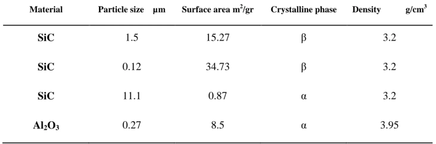
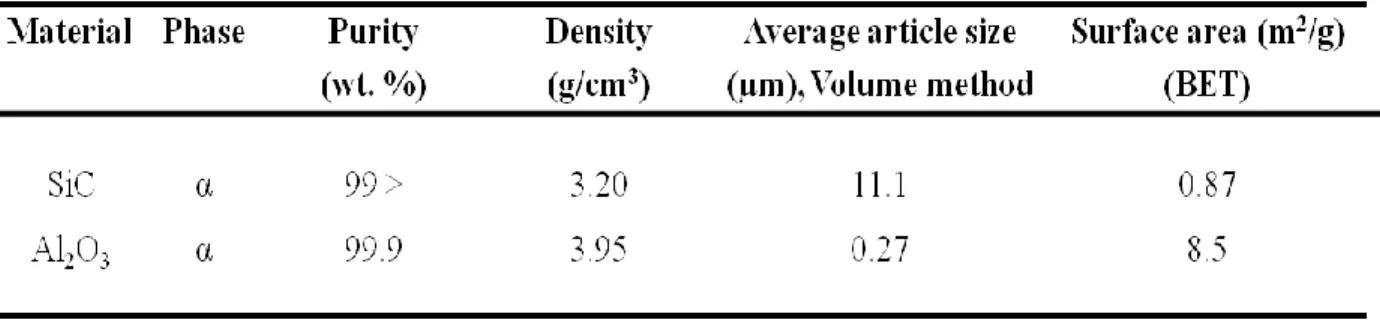
Table 2.1 Powder compositions and characterization of materials used in this study ... 33
Table 4.1 Summary of previous studies on the oxidation of SiC ... 47
Table 4.2 Characteristic of starting materials ... 58
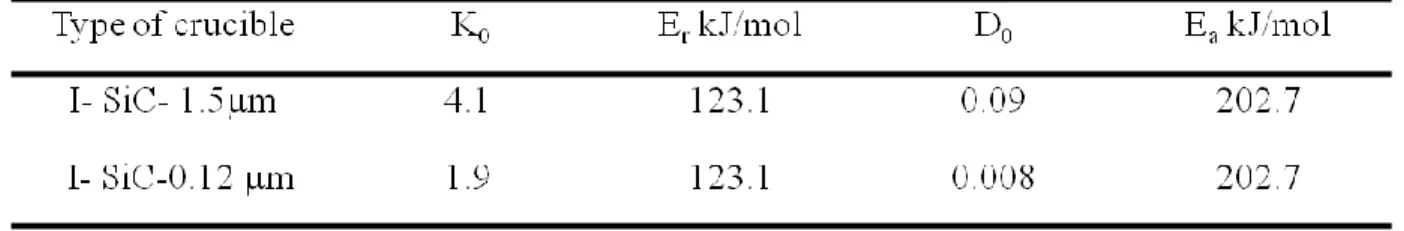
Table 4.3 Kinetics parameters values for the system I and III using the Eq. 4 for the temperature range of 910-1010 °C ... 60
Table 4.4 Physical properties used in the model ... 62
Table 5.1 Powder compositions and characterization of materials used in this study ... 77
Table 5.2 Effect of Al2O3 additions in calcined form on the flexural strength, open porosity and pore size ... 84
Table 5.3 Effect of Al2O3 additions in sol form on the flexural strength, open porosity and pore size ... 84
Table 5.4 Effects of Al2O3 additions in sol form on the flexural strength, open porosity and pore size where the total alumina was 35 wt. % ... 92
Table 6.1 XPS data for original and coated particles with 19.3 wt.% polymer ... 113
Table 6.2 Influence of polymer content on the flexural strength, open porosity and pore size ... 114
Table 6.3 Effect of forming pressure on the flexural strength, open porosity and pore size ... 122
Table 7.1 XPS data for original and after coating with alumina sol and polyethylene ... 140
Table 7.2 Mechanical and physical properties of the ceramics prepared by the developed method and traditional method, sintering at 1500 °C for 3hrs and forming pressure of 50 MPa ... 144
LISTE OF FIGURES
Figure 1-1Efficiency of various separation processes ... 5
Figure 1-2 The structure of a low density (left) and high density (right) of porous ceramics[10] .. 5
Figure 1-3 Mechanism of mullite formation using silica/ cristobalite with alumina [24] ... 9
Figure 1-4 Phase diagram of alumina and silica[30] ... 10
Figure 1-5 The crystal structure of boehimite[41] ... 13
Figure 1-6 Step processing in dip coating technique: a) immersion, (b) wetting, and (c) withdrawal [38, 42] ... 15
Figure 1-7 Interaction of inherent hydrated silica film on SiC surface with the alumina gel[53]. 17 Figure 1-8 A schematic drawing of liquid phase sintering [67] ... 19
Figure 1-9 A schematic diagram of the SiC particle size change after oxidation ... 21
Figure 1-10 Preparation of nano-composite without: (a) without grafting polymer and (b) separation with grafting polymer.[82] ... 24
Figure 1-11Schematic of different processing routs of porous SiC ceramics ... 27
Figure 1-12 Crystallization of the Schumacher Dia Schumalith F40 filter matrix during operation (right) and the silica-enriched layer on the surface of the silicon carbide grains within the Pall filter matrix (left)[118] ... 30
Figure 1-13 Pore size distribution of porous SiC ceramic (addition of the20µm graphite) (left) and agglomeration of α-Al2O3 particles in porous SiC ceramics [81]. ... 31
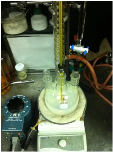
Figure 2-1 Processing set-up for the synthesis of alumina sol ... 34
Figure 2-2 A BUCHI reactor system for polymerization ... 35
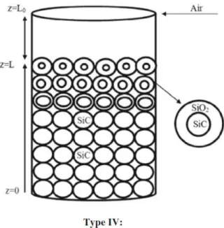
Figure 4-1 Schematic representation of oxidation of SiC in the TGA ... 50
Figure 4-2 SEM images of raw SiC powders: β-SiC-120nm (up) and β-SiC-1.5µm (down) ... 57
Figure 4-3 TGA curves of β-SiC powders 1.5 µm and 120nm ... 58
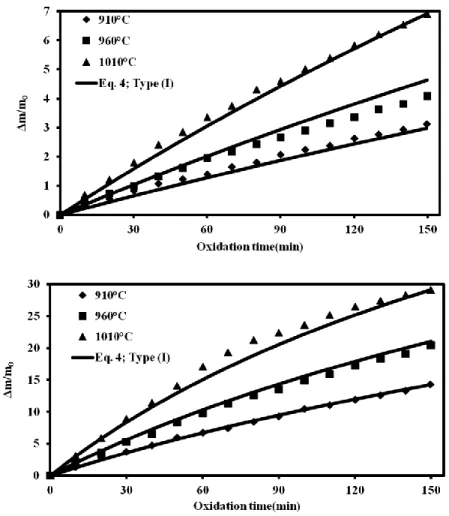
Figure 4-4 A comparison of the oxidation behaviour between experimental and calculated for β-SiC 1.5µm (up) and β-β-SiC 120 nm (down) at various temperature; type (I) ... 59
Figure 4-5 A comparison of the oxidation behaviour between experimental and calculated for
β-SiC 1.5µm (upper) and β-β-SiC 120 nm (lower) at various temperature; type (III) ... 61
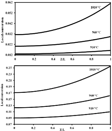
Figure 4-6 Local conversion vs. axial position in the bed for β-SiC 1.5µm (up) and β-SiC 120 nm (down) at different temperature reaction, reaction time 60 min; type (III) ... 63
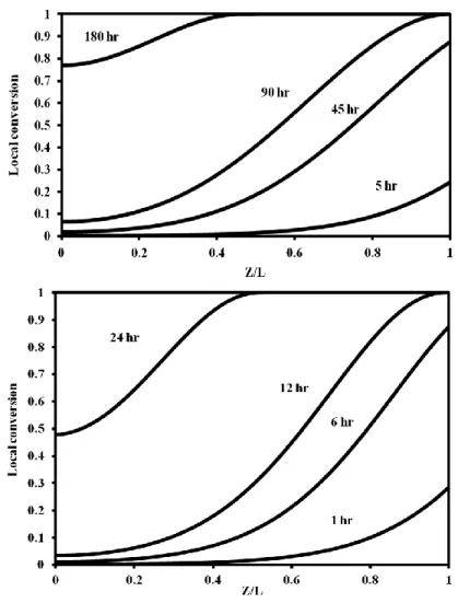
Figure 4-7 Local conversion vs. axial position in the bed for β-SiC 1.5µm (up) and β-SiC 120 nm (down) at 1010 °C for different reaction time; type (III). ... 64
Figure 5-1 SEM micrographs and particle size distribution of starting materials ... 78
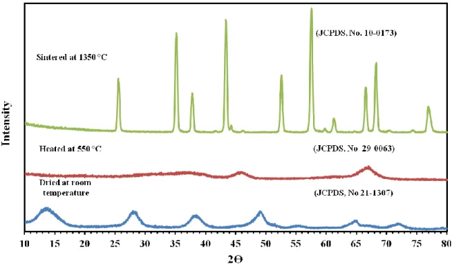
Figure 5-2 TEM images of alumina sol (a) dried and (b) calcined at 550 °C. ... 81
Figure 5-3 X-ray diffraction patterns for dried alumina sol and after heat treated ... 82
Figure 5-4 FTIR spectra obtained for the dried and heat treated boehmite samples ... 83
Figure 5-5 XRD patterns of porous SiC ceramics with different content of alumina and sources; a) calcined and b) alumina sol; sintered at the 1500 °C for 3 h (Al: alumina, C: cristobalite, M: mullite and S: silicon carbide). ... 85
Figure 5-6 SEM micrograph of porous SiC which was prepared by oxidation (0 wt. % alumina) in air at 1500 °C for 3h (up); XRD patterns of raw SiC powder oxidized at indicated temperature in air (down) (C: cristobalite; S: silicon carbide). ... 86
Figure 5-7 Pore size distribution in porous SiC ceramics at different alumina powder contents, . 87 Figure 5-8 SEM micrographs, XRD and pore size distribution of porous SiC ceramics sintered at 1500 °C for 3 hr in air, Where 10%wt. Alumina (in the calcined powder or sol form) was added into SiC particles ... 89
Figure 5-9 SEM micrographs, XRD and pore size distribution of porous SiC ceramics sintered at 1500 °C for 3 hr in air, Where 40%Wt. Alumina (in the calcined powder or sol form) was added into SiC particles ... 90
Figure 5-10 SEM micrographs and pore size distribution of porous SiC ceramics sintered at 1500 °C for 3 hr in air, where 35%wt. pure calcined alumina was added into SiC particles and where 20 wt% of calcined alumina was replaced by alumina sol ... 93
Figure 5-11 SEM micrographs SiC and alumina (35 wt. %) which was mixed in ethanol and
alumina sol ... 94
Figure 6-1 SEM micrographs and particle size distribution of starting materials. ... 105
Figure 6-2 TGA of three PE coated samples ... 108
Figure 6-3 SEM images of coated SiC and Al2O3 particles at different amount of polymer ... 111
Figure 6-4 TEM images of coated particles (11.7 wt.% polymer) ... 112
Figure 6-5 A TEM micrograph of the coated particles with 11.7 wt% of HDPE ... 114
Figure 6-6 Pore size distribution and SEM of porous SiC ceramics sintered at 1500 °C for 3 h in air, where 35%wt calcined alumina was added into SiC particles and where starting particles were not coated (a) and where were coated with 11.7 wt% of polyethylene (b) ... 115
Figure 6-7 XRD patterns of porous SiC ceramics; a) effect of polymerization and b) effect of sintering temperature; (Al: alumina, C: cristobalite, M: mullite and S: silicon carbide). .... 118
Figure 6-8 SEM micrographs SiC and alumina (35wt.%) which were mixed in ethanol (a) and coated by polymer via in situ polymerization (b) ... 119
Figure 6-9 SEM micrographs of coated samples which polymer filaments attach alumina nanopowders on the SiC particles ... 120
Figure 6-10 SEM of porous SiC ceramics sintered at 1550 °C for 3 h in air where 35%wt. calcined alumina was added into SiC particles and they were coated with 11.7 wt% of polyethylene ... 121
Figure 6-11 Pore size distribution and SEM of porous SiC ceramics sintered at 1500 °C for 3 h in air, where 35%wt. calcined alumina was added into SiC particles and where starting particle were coated with different amount of polyethylene ... 123
Figure 6-12 SEM morphologies of porous SiC ceramics sintered at 1500 °C for 3 hrs in air with the forming pressure of green bodies of 25 MPa and 100 MPa, where 35wt.% alumina was added into SiC particles and the starting particles were coated with 3.6 wt.% of polymer . 123 Figure 7-1 Scheme of the starting materials used for the fabrication of porous SiC ceramics: traditional process (right) developed method (left). ... 133
Figure 7-2 Schematic diagram of the novel fabrication route used for the preparation of porous SiC ceramics ... 134 Figure 7-3 Thermal Characterization of alumina sol and coated SiC and Al2O3 powders by
different routs ... 138 Figure 7-4 SEM images of original SiC and Al2O3 powders (a); after coating with alumina sol
(b); after polymerization ... 139 Figure 7-5 XPS spectra of original powders and after coating by alumina sol and polyethylene142 Figure 7-6 Morphology of the coated particles by sol-gel and In-situ polymerization routs ... 143 Figure 7-7 Pore size distribution of the porous SiC samples prepared by two different process,
sintering temperature 1500 °C and forming pressure was 50 MPa ... 144 Figure 7-8 The morphology of porous SiC ceramics fabricated by the traditional method at 1500
°C under air with the 35% wt Al2O3 ... 145
Figure 7-9 Morphology of porous SiC ceramics fabricated by the novel method at 1500 °C under air with the 35% wt Al2O3 ... 146
Figure 7-10 A comparison between crystalline phases of the porous SiC ceramics manufactured by the conventional method and the new process ... 147 Figure 7-11 Crystalline evoulotion of porous samples as the sintering temperature increases ... 151 Figure 7-12 Bubble formation during sintering of the porous SiC ceramics at 1600 °C under air
for 3h ... 152 Figure 7-13 Morphology of porous SiC ceramics fabricated by the novel method at 1600 °C
under air with the 35 wt% Al2O3 ... 153
LIST OF SYMBOLS
A Gas reactant
Bed surface area
Stoichiometric coefficient Concentration of gas reactant
Concentration of gas reactant at the surface of the bed
Molar density of SiC
Total molar density of gas
Pre-exponential factor in Arrhenius equation in Eq. 4.24
Diffusion coefficient of the reactant in gas in the bulk system
Effective diffusivity of the reactant gaseous in solid Pre-exponential factor in Arrhenius equation in Eq. 4.25
H.D.P.E High density polyethylene
Bed height
Crucible height Initial sample weight
Molar flux of gaseous reactant inside the powder Molar balance of the gaseous reactant in the crucible Radius of the crucible
Radius of un-reacted shell of powder Initial powder radius
Total surface area of the powder per unit volume
Temperature
Time for a complete reaction of the particles as defined in Eq. 4.4
Time to complete oxidation of the particles as defined in Eq. 4.4 Time to complete oxidation of the particles as defined in Eq. 4.10
Time to complete oxidation of the particles as defined in Eq. 4.27
Fractional conversion as defined in Eq. 4.5 Thickness of the oxide layer
Mole fraction of gas A in crucible
Mole fraction of gas A at bulk
Mole fraction of gas A at the surface of the bed
Local fractional conversion defined by Eq. 4.22
Z Dimensionless of bed height in the crucible (z/L) Z* Dimensionless of moving boundary in the bed
Function defined by Eq. 4.19
Function defined by Eq. 4.18
Function defined by Eq. 4.27 Function defined by Eq. 4.B1
Porosity
Stress
INTRODUCTION
Porous silicon carbide (SiC) ceramics have been attracting a great deal of research attention as they are found in a wide variety of high-temperature processes in the metallurgical and chemical fields. Due to their unique combination of physical and mechanical properties, such as excellent mechanical strength, good chemical resistance, high thermal conductivity and low thermal expansion number, these materials are known as the best material candidatesin filters, catalytic supports, separation membranes, high-temperature structural materials, kiln furniture, thermoelectric energy conversion, and the reinforcement of composites [1]. Depending on the special application of the porous ceramic, several processing routes have been proposed and developed for the manufacture of porous SiC ceramics, which can be grouped into 5 categories [1]: (i) partial sintering, (ii) replica, (iii) sacrificial template, (iv) direct foaming, and (v) reaction bonding techniques. To self-bond porous SiC ceramics a very high sintering temperature (above 2000 °C) is required due to the high covalent nature of the Si-C bond [2] and low self diffusion coefficient of SiC. In addition, during the operation of self-bonded porous SiC ceramics at high temperature in a humid environment and an oxidizing atmosphere, these materials are partially oxidized and elongated and eventually fail.
To fabricate porous SiC ceramics at lower sintering temperatures with a higher oxidation resistance, a reaction bonding technique was developed, which involves a mixture of a sub-micron sintering additive, such as alumina, and a pore former, such as graphite, with the SiC particles followed by pressing the powders to make a green body and heating the compact powders under air [3]. However, the main drawback of this process is the agglomeration of the sintering additive and poor dispersion of pore former in the starting materials, which degrades the mechanical and physical properties of the porous ceramics. Therefore, developing a new process at a low sintering temperature to improve control in pore size distribution and increase the mechanical properties and porosity simultaneously would be an interesting subject.
The main objective of this study is to develop mullite-bonded porous SiC ceramics with a combination of sol-gel and in-situ polymerization techniques with a reaction bonding process. Sol-gel processing is a well-known method to fabricate ceramic composite due to the low cost and high homogenous mixing. In addition, in-situ polymerization is a promising technique to synthesize organic-inorganic composites with enhanced mechanical properties. It is believed that
the addition of a sintering additive via the sol-gel route and a pore former by in situ polymerization is an appropriate choice to overcome the inhomogeneity of the starting particles and enhance and control the properties of the final ceramics. This method can fabricate a porous ceramic, which is strongly resistant to oxidation and with the desired filtration properties. It will make it possible to create a multifunctional, responsive and adaptive filter for various operating conditions, such as for advanced coal and biomass-based gas turbine power generation applications. In this method, SiC particles are coated by alumina via alumina sol and calcined alumina powders. Subsequently, polyethylene is layered on particles using in situ polymerization. By heating the green body, polyethylene is removed as a result of the reaction of the polymer with oxygen and consequently pores are created. Mullite is formed by the reaction between alumina and silica derived from SiC during the sintering process to bond SiC particles together. To help follow the results presented in this dissertation, a literature review concerning the important properties of the starting materials (SiC, alumina and mullite), sol-gel processing, in-situ polymerization technique, oxidation of SiC and previous works carried out on the porous SiC ceramics fabrication is given in Chapter 1. The materials used and our methodology to achieve the objectives are presented in Chapter 2. Chapter 3 briefly describes the organization of the papers. In Chapter 4, the passive oxidation of SiC powders is discussed from experimental results with high-temperature thermogravimetry analysis. The effects of oxidation temperature and particle size on the oxidation rate of SiC powders are investigated. In addition, the effect of the diffusion resistance on the oxidation rate of SiC powders is discussed in depth. Chapter 5 presents the results on the fabrication of porous SiC ceramics via reaction bonding with different amounts of alumina contents and sources (alumina in sol or calcined powders or a combination of them). The results showed that the alumina content and form played a crucial role on the mechanical and physical properties and morphology of the pore structure of the porous samples. In chapter 6, porous SiC ceramics were fabricated with the cooperation of the in-situ polymerization method and reaction bonding technique. It will be demonstrated that controlling the processing parameters, such as polymer content, and forming pressure make it possible to adjust the porosity and mechanical properties of the porous SiC ceramics. In Chapter 7, the application of sol-gel and in situ polymerization methods is investigated in detail to fabricate mullite bonded porous SiC ceramics via in-situ reaction bonding. The effect of the sintering temperature on the crystalline structure and morphology of the manufactured porous ceramics are
discussed. In Chapter 8 (general discussion), a full review regarding the most important factors affecting the mullite-bonded porous SiC ceramics and the effects of the implementation of sol-gel and in-situ polymerization are presented. Finally, Chapter 9 summarizes the most important conclusion of this thesis and lists some recommendations for future work in this area.
CHAPTER 1
LITERATURE REVIEW
1.1 Hot gas filtration
Since the 1990s ceramic filters, with fine pore size distribution, have been reported being used in a number of dust removal and gas treatments, especially when hot gases are present [4]. Typical industrial applications of hot gas filters include the following: biomass pyrolysis, biomass gasification [5], metal refining, incineration [6], metal recycling, coal gasification [7] radioactive waste, integrated gasification combined cycle (IGCC) [8] and pressurized fluidized bed combustion (PFBC) [5, 9]. The goals of hot gas filtration are to protect the downstream equipment, such as the gas turbine, to save energy and meet environmental regulations. The efficiency of ceramic filter test results versus particle size is compared to other particulate filters in Figure1-1 [16]. It has been reported that implementing the ceramic filters instead of the wet scrubber method results in increasing the efficiency of a coal gasification process by about 3%. Moreover, in a wide variety of processes, such as biomass gasification, in order to avoid undesirable condensation or desublimation reactions, the effluent gas must be cleaned at high temperature via ceramic filters.
Hot gas filters should operate reliably for more than 10,000 hours, with a high particulate removal efficiency, a high flow capacity and a low pressure drop. In addition, they should have high durability and reliability against mechanical and thermal stresses [4]. In ceramic filters, phase and matrix composition have been critical to the impact of the long-term thermal and chemical stability of the component during operation in porous ceramic candle filters.
Ceramic filters can be divided into high and low densities in terms of media. High density porous ceramics consist of sintered grains, preferably of silicon carbide, alumina or cordierite, with a porosity in the range of about 40% and have a stable mechanical strength (O-ring pressure strength of above 20 MPa). While in low density ceramics, the main component is typically alumosilicate fibers and the porosity can reach up to 90%. The low density ceramic filters have high porosity, they suffer from a low mechanical structure due to the loose structure of fibers and, consequently, break easily. Also, during the cleaning process of the low density ceramic filter, the intensity of the back pulse should be controlled to protect the fiber structure [10].
Figure 1-1Efficiency of various separation processes
Figure 1-2 presents a typical structure of low and high densities of porous ceramics. In the high density porous ceramics a thin membrane layer with smaller pores covers the support material. The efficiency of this kind of filter is very high (in the order of 99.99%).
1.2 Ceramic materials and their properties
With respect to filter materials, strength, thermal shock resistance, thermal expansion, thermal conductivity, fracture toughness, hardness and chemical reactivity are important parameters in the selection of a reliable, durable, filter material. Generally, porous ceramic filter material can be divided into non-oxide and oxide materials. Among these materials, SiC, alumina and mullite are the most common [11].
1.2.1 Silicon carbide
Silicon carbide (SiC) known as carborundum offers without a doubt one of the most important structural ceramics in various industrial products, such as abrasive materials, refractories and heating elements [12]. It is produced worldwide in tonnage quantities using the Acheson process by reaction in a batch consisting principally of high-purity sand and low-sulfur coke at 2200-2500 °C in an electric arc furnace according to the following reaction:
SiO2 + 3C → SiC +2CO 1-1
After crushing the crystalline product, it is washed in acid and alkali. Then the iron is removed by magnetic techniques and, finally, the product is dried. SiC can resist the attack of any acids, alkalis or molten salts up to 800 °C. Also, SiC has excellent mechanical and physical properties, such as high thermal conductivity coupled with low thermal expansion and high strength. Therefore, silicon carbide is an outstanding ceramic for severe environments. The properties of silicon carbide are shown in Table 1.1 [12].
1.2.2 Alumina
Aluminum oxide (Al2O3) is mostly produced on a commercial scale using the Bayer process. The
Bayer process includes the physical beneficiation of bauxite, digestion, clarification, precipitation and calcination, followed by crushing, milling and sizing. The temperature of calcination of washed aluminum hydroxide is between 1100-1200 °C. The most common crystalline form of alumina is known as corundum [13, 14]. It has Al3+ in octahedral coordination, which occupies two-thirds of the available sites [15]. Table1.2 presents the property of alumina.
Table 1.1 Mechanical and physical properties of SiC
Property Metric
Density (gm/cc) 3.1
Flexural strength (MPa) 550
Poisson modulus 0.14
Thermal conductivity ( W/m.K) 120
Coefficient of thermal expansion (/ C) 4 ×10⁻⁶
Specific heat (J/Kg.K) 750
Table 1.2 Mechanical and physical properties of alumina
Property Metric
Density ( gm/cc) 3.97
Flexural strength (MPa) 379
Poisson modulus 0.22
Thermal conductivity ( W/m.K) 35
Coefficient of thermal expansion (/ C) 8 ×10⁻⁶
Specific heat (J/Kg.K) 880
1.2.3 Mullite
In contrast to the Al-Si-oxides, like sillimanite (Al2O3.SiO2, 62.92 wt% Al2O3), andalusite, and
cyanite, mullite (2SiO2.3Al2O3) has been recognized as the only stable crystalline compound
under normal atmospheric pressure in the binary system of SiO2-Al2O3 [16]. The structure of
aluminum and/or silicon tetrahedral. In the X-ray diffraction of mullite at 26° (2Ө-CuKα), a double peak can be observed due to the orthorhombic structure or a single pick can be detected at 26° related to the tetragonal structure, which is a metastable phase [17]. The mullite material has two stoichiometric crystalline (2SiO2.3Al2O3 or SiO2.2Al2O3).
The properties of mullite, such as the high temperature melting point (>1800°C), low thermal expansion (4.5–5.6×10⁻⁶ K-1 in a range of 20 °C and 1000 °C), good thermal shock resistance, low density (3.16-3.22 g.cm-3), high creep resistance and good chemical stability, are similar to the properties of SiC. As a result, it has found widespread applications in high temperature structural materials where the environment temperature changes rapidly [18].
During the past few decades, various preparation methods, such as the reaction sintering of mechanically mixed powder [19], hydrothermal treatment of mixtures of sols [20, 21], and chemical vapor deposition [22], were applied to synthesize mullite. In general, mullite formation can be classified into three different routes as follows: sinter-mullite, fused-mullite and chemical mullite. Sinter-mullite is a conventional process, i.e., the mixing of alumina and silica powders [23]. In this method, mullitization occurs by the interdiffusion of the solid-solid or transient liquid phase reactions of aluminium, silicon and the oxygen atom [24]. Thus, the particle size of the starting powders is an important factor, which affects the mullitization temperature [19]. The drawback of this method is that the size of the particles is not enough to accomplish the complete mullitization at a relatively low sintering temperature. Nurishi et al. [25] investigated the effect of the crystallization of cristobalite by X-ray diffraction studies on the reaction sintering of Al2O3
and amorphous SiO2 compacts at temperatures of 1300-1500 °C. In the system consisting of
amorphous silica and α-Al2O3, mullitization involves two steps. Prior to mullitization in the
temperature range of 1300-1500 oC liquid formation was observed. In this system first the transformation of quartz to cristobalite occurred. Moreover, mullitization during the reaction sintering of quartz and α-Al2O3 powders was studied by means of TEM. It was suggested that the
reaction sequence begins with the formation of a transient glass phase on the surface of quartz grains. This viscous silica melt penetrates into α-Al2O3 particles and concurrently incorporates Al
by the dissolution of α-Al2O3 [26]. Nucleation of mullite was observed mainly at the
α-Al2O3/silica melt contact [27, 28]. Saruhan et al. [24] observed two different mullite mechanisms
depending on the use of quartz or cristobalite. They prepared two different green samples consisting of SiO2 glass plus α-Al2O3 and cristobalite-α-Al2O3. They proposed that mullite
formation is a multiple-step process: mullite nucleation, high mullitization, a temperature range of low mullitization and the area of high mullite formation rates. In the quartz-alumina system they suggested that before the beginning of mullite formation, densification occurs in the SiO2
-Al2O3 sample through the viscous flow sintering and in the other sample it was characterized by
solid-state sintering. They reported that at high temperatures the content of mullite in the crisoblite-α-Al2O3 system is higher than in SiO2-α-Al2O3 (Figure 1-3) [24].
Figure 1-3 Mechanism of mullite formation using silica/ cristobalite with alumina [24]
Also, Amar P.S. Rana and his coworkers[29] investigated the mullite formation from cristobalite and quartz in mixtures with α-Al2O3 at 1415 °C. Similarly, they reported in quartz, a liquid first
forms on the surfaces of quartz that result in the occurrence of an intermediate liquid phase on the transformation of quartz to cristobalite. The liquid acts as the precursor to the formation of mullite by reacting with α-Al2O3. They observed that mullite was detected earlier in the
cristobalite containing mixtures under a similar sintering process to quartz [29].
In 1924, Bowen and Greig [30] reported the first phase equilibrium diagram at standard conditions and showed that mullite crystallized from a stoichiometric 2SiO2.3α-Al2O3 contained
71.8% Al2O3. It was reported that this is the only composition that melted incongruently at 1828
In 1962, Aramaki and Roy [31] observed mullite with a solid solution of alumina in the range of 71.8-74.3 wt% Al2O3. They reported that mullite melts congruently at 1850 °C. In another study,
it was shown that at temperatures above 1828 °C, mullite does not form, and α-Al2O3 is dissolved
in the SiO2 liquid to form aluminosilicate liquids. In summary, the source of species, their
chemical purity and particle size distribution are the most important factors in the rates and temperature of mullite formation [24].
Figure 1-4 Phase diagram of alumina and silica[30]
The physical and mechanical properties of mullite are shown in Table 1.3. Regarding more recent developments in processing technologies, sol-gel, precipitation, hydrolysis, spray pyrolysis and chemical vapour deposition are other possible techniques for the synthesis of mullite [32].
1.2.3.1 Synthesis of mullite using the sol-gel method
In this method mullite is produced by adding sols or mixing sols and salts as starting materials. The main difference of this method from the conventional method is the particle size. In the sol-gel method, usually the particle size of sols is very small (nano sized), about ten to several tens nano-meters. Alumina sol and silica sol are major starting materials.
Silica sol can be obtained from fumed silica, colloidal silica as well as the hydrolysis of silicon alkoxides. Alumina sol can be obtained by various sources, such as isopropylate, aluminium chloride, aluminium sulphate, aluminium acetate, the dispersion of ultra-fine particles of γ-Al2O3
and the dispersion of pseudo-boehmite γ-Al(OH). Boehmite is the most common starting precursor of alumina sol [33]. Sacks et al. [34] fabricated mullite by coating silica on α-Al2O3
particles. First, α-aluminawith an average particle size of 0.2 µm was suspended in ethanol. The suspension was mixed with the TEOS/ethanol solution to form a composite powder. The hydrolysis of TEOS was carried out by adding ammonia solution. The pH was kept in the 9-10 range to make a surface charge for electrostatic stabilization. After precipitation, the composite particles were filtrated and washed followed by the preparation of green compacts by slip casting and drying at 80 °C. Finally, the green compacts were fired in air. It was observed that powder compacts converted to mullite at temperatures 1400 °C.
Table 1.3 Physical and mechanical properties of mullite [35]
Density 3.2 (g/cm3)
Young’ Modlus 130 (GPa)
Fracture of Rupture 2-4(MPa.m-1/2)
Modulus of Rupture 160(MPa)
Thermal Expansion Co- Efficient 4.5-5.6 (× 10-6/°C)
Thermal conductivity 4-6 ( 100 -1400 °C ) (W/m.K)
Maximum operating temperature 1725°C in air
Flexural strength 180(MPa)
Similarly, Bartsch et al. [36] successfully produced mullite at sintering temperatures below 1300 °C via ɣ-Al2O3 nano particles with silica by the sol-gel method. They proposed that the viscosity
enhanced the densification process. We can conclude from the literature review that in the reaction sintering of SiO2 and alumina compound, the sintering behaviour and properties of
mullite strongly depend on the sources of SiO2 and alumina.
1.3 Sol-gel processing and coating of particles
As stated in the previous section, sol-gel is one technique, which can be applied to the synthesis of ceramic and also to coat the ceramic substrate. Thus, a brief discussion of the fundamentals of the sol-gel process is required. The definition of the sol-gel (solution-gelation) process is “a preparation process of precursors using liquid colloidal solutions of metal salts to obtain a gel by a subsequent heat treatment.” In other words, this method is a wet chemical route to synthesize materials starting from either a colloidal suspension of solid particles or clusters in a liquid (sol) and later to produce an integrated solid skeleton filled with a solvent (wet gel). A sol consists of a dispersion of solid particles (colloids), which are very small (1nm~1µm), such that gravitational force is negligible in a liquid. The dominant interactions in sol are Vander Walls, columbic and steric forces. In order to stabilize a sol, an electric double layer or steric repulsion, or their combination must be established [37]. When solvent from the gel is removed, depending on the type of drying either through ambient pressure or under supercritical conditions a xerogel or aerogel will be formed. Changing the temperature, evaporation and some chemical reactions affect the sol gel process.
In the aqueous-based process, there are two distinct reactions: hydrolysis and condensation or polymerization. Hydrolysis of the metal cations is often given by the following general mechanism:
2 ( )
n
n
M nH OM OH nH 1-2 Ceramic powder can be synthesized mostly from cation metal ions (MZ+) sol. The hydrolysis of this sol is given by the following:
( 1)
2 2 1
( )bZ ( )b z
M H O M H O OH H 1-3 Moreover, adding dilute acid breaks up aggregates of hydrous metal oxide or hydroxides. Size
various factors, such as pH, solid content, temperature, organic and inorganic additive addition and starting materials, influence the hydrolysis and condensation rate of the sol-gel process [37]. For instance, in acidic solutions, the hydrolysis reaction is faster than condensation, which increases the development of larger and linear molecules and under basic conditions; the rate of condensation reaction is more than hydrolysis [38]. Colloidal and polymeric methods are two techniques used to obtain a homogeneous sol. In the colloidal method, a large quantity of water is added to hydrolyze the alkoxide followed by the addition of acid in order to peptize the agglomerates. Acid breaks the agglomerates by electric charge repulsion. Yoldas developed clear bohemite sol (aluminium hydroxide) with the colloidal method. He applied aluminum isopropoxide (AIP) and the molar ratio of distillated water to AIP was 100:1. Peptization was observed with nitric acid or HCL at 90 °C with 0.07 moles of acid per mole of precursor [39]. The crystal structure of boehmite is composed of double AlO6 octahedral chains as shown in
Figure 1-5 giving rise to a dimer, which is interconnected by hydrogen bonds between the hydroxyl groups. The specific density of boehmite is 3.01 g/cm3 [15].The morphology cell of boehmite is cubic orthorhombic [40].
Among metal alkoxides, aluminum, titanium, and zirconium alkoxides are the most common starting materials for the sol-gel process because of their relatively high reactivity, especially to water.
In addition to the synthesis of ceramic, the coating of the substrate with sol-gel processing is especially suitable for corrosive protection and a thermal barrier for various materials. Besides the sol-gel method, various technologies have been applied for coating ceramic on a substrate. These include chemical vapour deposition (CVD), physical vapor deposition (PVD), sputtering and plasma spray. The sol-gel coating has several advantages over the mentioned methods. It is simple, relatively low cost, has high homogeneity and potential for use in the coating of complex geometries.
Prior to gelation, a sol can be applied for the formation of thin, uniform films by either dip coating, spinning or spraying a film onto an appropriate substrate. Dip coating is more common than the spinning method and was first commercially used for preparing thin films in 1939 using sol–gel technology [42]. A simple approach for depositing a thin film of solution onto various shaped objects, dip coating involves five stages: immersion of a substrate into a reservoir of solution, start up, deposition, drainage and evaporation. This method does not require any special apparatus. The liquid film formation is attained by gravity draining the liquid solution and solvent evaporation. A thick film can be applied through multiple coating. During drying, by removing the water or alcohol between the colloidal units, the sol is transformed to a gel. The final step is firing at temperatures above 150 °C, which leads to the gel becoming consolidated. In the drying step, the formation of cracks may occur due to the significant stress [38]. It is well known that the thickness of the deposited liquid film (position c in Figure 1-6) strongly depends on the selected withdrawal speed and is directly proportional to the withdrawal speed as well as the soaking time.
Figure 1-6 Step processing in dip coating technique: a) immersion, (b) wetting, and (c) withdrawal [38, 42]
Furthermore, the sol concentration has to be carefully selected. A high concentration sol may lead to crack formation during the drying and firing process. Landau et al. [43] estimated the thickness of the liquid film with the help of following equation:
2 3 1 1 6 2 ( ) 0.944 ( ) L LV L U h g 1-4
where h is the deposited film thickness, L,Lare the viscosity and density of the liquid, U is the substrate speed of the liquid, g, the gravitational acceleration constant and LV is the liquid-vapor surface tension. M. Guglielmi et al. investigated the effect of withdrawal speed on the thickness of the SiO2 and TiO2 coating. They reported that the relation between thickness and speed is U1/2
instead of U2/3 [44]. Shih et al. [45] applied the sol-gel method to distribute the additives onto the surface of silicon nitride. They observed that with the sol-gel technique boehimite was distributed uniformly on the surface of silicon nitride.
Therefore, the sol-gel method can be applied as a way to create the secondary phase and improve the homogeneity of the microstructure. The creation of the secondary phase helps to meet two goals: sintering aid to lower the sintering temperature, or application of grain growth inhibitor to improve the thermal stability of the core particles. Chia-Yi Yang et al. [46] extended the work of Shih et al [45]. They investigated the coating of aluminium oxide on SiC particles. They used
![Figure 1-3 Mechanism of mullite formation using silica/ cristobalite with alumina [24]](https://thumb-eu.123doks.com/thumbv2/123doknet/2329546.31343/33.918.269.656.352.616/figure-mechanism-mullite-formation-using-silica-cristobalite-alumina.webp)