Frequency control in the presence of renewable energy
sources in the power network
by
Md. Jahidur RAHMAN
THESIS PRESENTED TO ÉCOLE DE TECHNOLOGIE SUPÉRIEURE
IN PARTIAL FULFILLMENT FOR A MASTER’S DEGREE
WITH THESIS IN ELECTRICAL ENGINEERING
M.A.Sc.
MONTREAL, NOVEMBER 9, 2017
ÉCOLE DE TECHNOLOGIE SUPÉRIEURE
UNIVERSITÉ DU
QUÉBECThis license means that it is prohibited to reproduce, store or distribute all or part of this document. The reader, who wishes to print or store on another media an important part of the document, must request permission from the author.
THIS THESIS HAS BEEN EVALUATED BY THE FOLLOWING BOARD OF EXAMINERS
Prof. Maarouf Saad, Thesis Supervisor
Department of Electrical Engineering, École de technologie supérieure
Dr. Hasan Mehrjerdi, Thesis Co-supervisor
Department of Electrical Engineering, Qatar University
Prof. Pierre Jean Lagacé, President of the Jury
Department of Electrical Engineering, École de technologie supérieure
Dr. Dalal Asber, External Examiner IREQ, Hydro-Québec
THIS THESIS WAS PRESENTED AND DEFENDED
IN THE PRESENCE OF A BOARD OF EXAMINERS AND THE PUBLIC ON OCTOBER 27, 2017
ACKNOWLEDGMENTS
First of all, I pay my gratitude to my almighty ALLAH (SWT), who gives me the strength, courage and patience to successfully completing this thesis work at last. After this thesis, I just offer my sincere, thanks and deep recognition to all those who helped me complete my research project in optimal conditions.
I sincerely thank my director of Research, Prof. Maarouf Saad, who gave me the opportunity to carry out my research work under his kind supervision. His support, encouragement and ideas that were much appreciated throughout this research work. He is not only my mentor, but also socially my teacher and philosopher.
I would like to thank my Co-supervisor Dr. Hasan Mehrjerdi, Assistant Professor in the Department of Electrical Engineering at Qatar University for his assistance, guidance and continuous support throughout my research.
Also, I would like to thank Prof. Pierre Jean Lagacé, President of the Jury and Professor, Department of Electrical Engineering at the École de Technologie Supérieure and Dr. Dalal Asber, external examiner, IREQ, Hydro-Québec, who evaluated my thesis and gave me their valuable suggestions and helpful advice.
I am very much grateful to Dr. Moustapha Dodo Amadou, Lecturer in the Department of Electrical Engineering at the École de Technologie Supérieure, who helped me in every moment of my research and project organization.
Finally, I am also very grateful to my elder brother Dr. Mohammad Habibur Rahman for all he has done for me since my childhood. He was always there to guide and support me to make my dreams come true. I cannot go without thanking my dear wife Fatima Tuj Jhohora (Sarna) for her supports throughout my three years of research and writing. I just cannot find enough words to express my gratitude and love for them.
FREQUENCY CONTROL IN THE PRESENCE OF RENEWABLE ENERGY SOURCES IN THE POWER NETWORK
Md. Jahidur RAHMAN ABSTRACT
Distributed generation (DG) becomes more popular power generation system in the presence of power engineering sector. It has environmental and economic benefit compared with other power generation system and run new technologies to have more efficient and less pollution in the environment. Due to the fluctuating behavior of renewable energy sources (RES), balancing, production and demand are not an easy task to control because it is not possible to get constant power from the renewable energy sources due to the natural situation. That’s why control of frequency in the power systems becomes more difficult due to the increasing of penetration of renewable resources. Therefore, a more effective control technique is needed to avoid a network collapse during power distribution.
To better understand the technology of DG, methods of control, regulation of frequency-related factors, the impact of DG on the voltage, power quality, and frequency during its connection to the grid distribution is identified in introduction part and the literature review based on DG in chapter I. Power grid connected to a wind turbine has been discussed in chapter II. Three scenarios of power system operation with control technique have been discussed for a hybrid diesel / high-penetration wind-based energy storage system in chapter III. In this application, PID and the fuzzy logic controller have been compared to each other to observe the fluctuation behavior of frequency. Therefore, some limitations and prospects of this methodology are identified in the conclusion.
Keywords: active power, battery, control, distributed generation, frequency, fuzzy logic controller, isolated-grid, PID controller, wind power.
CONTRÔLE DE FRÉQUENCE EN PRÉSENCE DE SOURCES D'ÉNERGIE RENOUVELABLE DANS LE RÉSEAU D'ALIMENTATION
Md. Jahidur RAHMAN RÉSUMÉ
La génération distribuée (DG) devient de plus en plus populaire comme système de génération d'électricité dans le secteur énergétique. DG a des avantages environnementaux et économiques par rapport à d'autres sources de production d'électricité. Elle exploite de nouvelles technologies pour être plus efficace et moins polluante dans l'environnement. En raison du comportement intermittent des sources d'énergie renouvelables (RES), il est difficile de contrôler l'équilibrage, la production et la demande. Ceci est dû à la difficulté de garantir une puissance constante des sources d'énergie renouvelables. De plus et en raison d’un taux de pénétration élevé des ressources d’énergie renouvelables, le contrôle de la fréquence dans les systèmes de puissance devient plus difficile. Par conséquent, une technique de contrôle plus efficace est nécessaire pour éviter un effondrement du réseau pendant la distribution d'énergie.
Pour mieux comprendre la technologie des DGs, le chapitre I présente les méthodes de contrôle, les facteurs liés aux fluctuations de la fréquence, l'impact de la DG sur la tension et la qualité de l'énergie lors de la connexion au réseau de distribution. Le réseau électrique connecté à une éolienne a été examiné au chapitre II. Trois scénarios de fonctionnement du système de puissance avec technique de contrôle ont été discutés pour un système de stockage hybride diesel / énergie éolienne à haute pénétration au chapitre III. Dans cette application, le PID et le contrôleur flou ont été comparés pour observer le comportement de fluctuation de la fréquence. Par conséquent, certaines limites et perspectives de cette méthodologie sont identifiées dans la conclusion.
Mots-clés: puissance active, batterie, contrôle, génération distribuée, fréquence, contrôleur de flou, réseau isolée, régulateur PID, énergie éolienne.
TABLE OF CONTENTS Page INTRODUCTION ...3 0.1 General ...3 0.2 Motivation ...4 0.3 Objective ...6
CHAPTER 1 LITERATURE REVIEW ...7
1.1 Concept of Traditional Power Systems ...7
1.2 Concept of New Power System ... 8
1.3 The Distributed Generation (DG) ... 9
1.3.1 Definition ... 10
1.3.2 Benefits of DG ... 10
1.3.3 Drawbacks of DG ... 11
1.3.4 The technologies of DG ... 12
1.3.5 Impact of DG on Power System ... 14
1.3.6 Impact of DG on Voltage Regulation ... 14
1.3.7 Impact of DG on Losses ... 14
1.3.8 Impact of DG on the Feeder Protection ... 14
1.3.9 Impact of the power converter on the DG ... 14
1.3.10 Protection coordination ... 16
1.4 Islanging of power network ...17
1.4.1 Intentional islanding... 18
1.4.2 Islanding dectection ... 18
1.5 Control of Frequency ...19
1.6 Micro grid ... 23
CHAPTER 2 CONNECTION OF WIND POWER IN THE POWER NETWORK ...25
2.1 Introduction ...25
2.1.1 Overview ... 25
2.1.2 Principle of wind generation ... 25
2.2 Conversion system of wind energy ...27
2.3 The technical operation of wind turbine ...28
2.3.1 Types of wind turbines ... 28
2.3.1.1 The variable speed squirrel cage wind turbines ... 28
2.3.1.2 Wind turbine induction generator (WTIG) ... 29
2.3.1.3 Doubly-fed induction generator (DFIG) ... 29
2.3.1.4 Permanent magnet synchronous generator (PMSG) at variable... speed ... 29
2.4 Connection of wind power to the grid ...36
2.4.1 Network stability ... 36
2.4.3 Case study: connecting a wind turbine to the power grid without……….
stroge system ... 38
CHAPTER 3 FLUCTUATION BEHAVIOR OF FREQUENCY FOR A HYBRID / WIND POWER BASED BATTERY STORAGE SYSTEM WITH DIFFERENT CONTROLLERS ...45
3.1 Introduction ...46
3.2 The system of WDHS ...46
3.2.1 The operation modes of WDHS system ... 47
3.2.2 System combination of WDWS ... 47
3.2.2.1 The synchronous machine SM ... 47
3.2.2.2 The Wind turbine ... 48
3.2.2.3 Secondary load system ... 48
3.2.2.4 The energy storage system BESS ... 48
3.3 The network control system of WDHS ...49
3.3.1 The frequency control system of WDHS ... 50
3.3.2 The control of BESS ... 54
3.4 Case study: connecting a wind turbine to the power grid with storage system ...54
3.5 Simulation: Scenario 1 ...56
3.5.1 Frequency control by PID, When (PT > PL) where, PS fully charged ... 56
3.5.2 Fuzzy logic controller ... 59
3.5.2.1 Introduction ... 59
3.5.2.2 Fuzzy logic membership function and rules ... 60
3.5.3 Frequency control using Fuzzy logic controller, When (PT > PL) where, PS fully charged ... 64
3.5.4 Comparison between PID and fuzzy logic controller to control the frequency, when (PT > PL) where, PS fully charged ... 67
3.6 Simulation: Scenario 2 ...68
3.6.1 Frequency control by PID, When (PT > PL) where, PS is charged ... 68
3.6.2 Frequency control using Fuzzy logic controller, When (PT > PL) where, PS is charged ... 73
3.6.3 Comparison between PID and fuzzy logic controller to control the frequency, when (PT > PL) where, PS is charged ... 78
3.7 Simulation: Scenario 3 ...79
3.7.1 Frequency control by PID, When (PT > PL) where, PS is discharged ... 79
3.7.2 Frequency control using Fuzzy logic controller, When (PT > PL) where, PS is discharged ... 84
3.7.3 Comparison between PID and fuzzy logic controller to control the frequency, when (PT > PL) where, PS is discharged ... 89
CONCLUSION ...91
RECOMMANDATIONS ...93
LIST OF TABLES
Page
Table 2.1 Parameters of the buses for an electrical network ... 37
Table 2.2 Wind turbine generation systems parameters ... 39
Table 3.1 A hybrid network with BESS systems parameters ... 55
LIST OF FIGURES
Page
Figure 1.1 Traditional concept of power sypply ... 08
Figure 1.2 New concept of power supply ... 09
Figure 1.3 DG (with and without) voltage profiles ... 13
Figure 1.4 Mal trip and fail to trip ... 15
Figure 1.5 DG connected with power network using transformer ... 16
Figure 1.6 Islanding of a DG based power system ... 17
Figure 2.1 Different operating wind farms in Quebec ... 26
Figure 2.2 The conversion system of wind energy ... 28
Figure 2.3 Wiind turbine with a squirrel-cage induction generator ... 29
Figure 2.4 General structure of a wind turbine induction generator ... 30
Figure 2.5 Control systems for wind turbine induction generator ... 30
Figure 2.6 Operating principle of the doubly-fed induction generator ... 31
Figure 2.7 Power flow of DFIG ... 32
Figure 2.8 Adjusting power characteristic for a DFIG ... 33
Figure 2.9 General block diagram of PMSG wind turbine ... 36
Figure 2.10 A wind turbine asynchoronous generator power network ... 39
Figure 2.11 Block diagram of frequency control using PID controller ... 40
Figure 2.12 8-bit three phase digital signal ... 41
Figure 2.13 (a) Power from main load, (b) Power from wind turbine, (c) Power ... from secondary load ... 42
Figure 2.14 (a) Speed generated by asynchronous generator, (b) Frequency at ... load bus ... 43
Figure 3.1 Wind diesel generation system with energy storage system ... 47
Figure 3.2 Simulink models of power converter and BESS block ... 49
Figure 3.3 Power sharing and the battery charging and discharging conditions of ... WDHS system ... 50
Figure 3.4 Block diagram of the frequency control system ... 53
Figure 3.5 Frequency control system using power sharing ... 53
Figure 3.6 Simlink model of hybrid network with BESS in an isolated area wind ... mode only ... 55
Figure 3.7 (a) Power from wind turbine, using PID controller ... 56
Figure 3.7 (b) Power absorbed by Secondary load and (c) Power absorbed by the main .... load, using PID controller ... 57
Figure 3.8 Operational block diagram of frequency control using PID controller ... 57
Figure 3.9 Frequency at load bus and (b) Speed generated by asynchronous generator, .... using PID controller ... 58
Figure 3.10 (a) Voltage at load bus, using PID controller ... 58
Figure 3.10 (b) Current at secondary loads, using PID controller ... 59
Figure 3.11 Operation of fuzzy logic controller ... 60
Figure 3.12 (a) Membership function, Input variable 1 ... 61
Figure 3.12 (b) Membership function, Input variable 2 ... 62
Figure 3.13 Membership function of output variable ... 63
Figure 3.14 (a) Power from wind turbine, (b) Power absorbed by secondary load and (c) Power absorbed by the main load, using Fuzzy logic controller ... 64
Figure 3.15 Simulink block diagram of fuzzy logic controller ... 65
Figure 3.16 (a)Frequency at load bus and (b) Speed generated by asynchronous generator, using Fuzzy logic controller ... 66
Figure 3.17 (a) Current at secondary loads, using Fuzzy logic controller ... 66
Figure 3.18 Fluctuation observations of frequency compare between PID controller and Fuzzy logic controllers when battery fully charged ... 67 Figure 3.19 (a) Power from wind turbine, (b) Power absorbed by main load, (c) power
from battery and (d) Power absorbed by Secondary load, using PID controller ... 69 Figure 3.20 (a) State of charge (SOC) of battery, (b) Current in the battery and (c)
Voltage in the battery, when battery is charging ... 70 Figure 3.21 (a) Frequency at load bus and (b) Speed generated by asynchronous
generator, using PID controller ... 71 Figure 3.22 (a) Voltage at load bus, using PID controller ... 72 Figure 3.22 (b) Current at secondary loads, using PID controller ... 72 Figure 3.23 (a) Power from wind turbine, (b) Power absorbed by main load using Fuzzy
logic controller ... 73 Figure 3.23 (c) Power from battery and (d) Power absorbed by Secondary load, using
Fuzzy logic controllerr ... 74 Figure 3.24 (a) State of charge (SOC) of battery, (b) Current in the battery and (c)
Voltage in the battery, when battery is charging ... 75 Figure 3.25 (a) Frequency at load bus and (b) Speed generated by asynchronous
generator, using Fuzzy logic controller ... 76 Figure 3.26 (a) Voltage at load bus, using Fuzzy logic controller ... 77 Figure 3.26 (b) Current at secondary loads, using Fuzzy logic controller ... 77 Figure 3.27 Fluctuation observations of frequency compare between PID controller and
Fuzzy logic controllers when battery is charging ... 78 Figure 3.28 (a) Power from wind turbine, (b) Power absorbed by main load, (c) Power
from battery and (d) Power absorbed by secondary load, using PID controller ... 80 Figure 3.29 (a) State of charge (SOC) of battery, (b) Current in the battery and (c)
Voltage in the battery, when battery is discharging ... 81 Figure 3.30 (a) Frequency at load bus and (b) Speed generated by asynchronous
generator, using PID controller ... 82 Figure 3.31 (a) Current at secondary loads, using PID controller ... 83
Figure 3.31 (b) Voltage at load bus, using PID controller ... 84 Figure 3.32 (a) Power from wind turbine, (b) Power absorbed by main load, (c) Power
from battery and (d) Power absorbed by secondary load, using Fuzzy logic controller ... 85 Figure 3.33 (a) State of charge (SOC) of battery, (b) Current in the battery and (c)
Voltage in the battery, when battery is discharging ... 86 Figure 3.34 (a) Frequency at load bus and (b) Speed generated by asynchronous
generator, using Fuzzy logic controller ... 87 Figure 3.35 (a) Current at secondary loads, using Fuzzy logic controller ... 88 Figure 3.35 (b) Voltage at load bus, using Fuzzy logic controller ... 89 Figure 3.36 Fluctuation observations of frequency compare between PID controller and
LIST OF ABBREVIATIONS, ACRONYMS DG Distributed Generation
Crotor Rotor side converter DFIG
Cgrid Grid side converter
PID Regulator Proportional, Integral, Derivative Kp Proportional gain of PID controller
Kd Derivative gain of a PID controller Ki Integral gain of a PID controller SW Bus Balance bus or Swing Bus PV Bus Generator bus
PQ Bus Load bus
DFIG Double-fed induction generator WRSG Wound rotor synchronous generator PMSG Permanent magnet synchronous generator WTIG Wind turbine induction generator
WRIG Wound rotor induction generator WDHS Wind diesel hybrid system IGBT Insulated-gate bipolar transistor AGC Automatic Generation Control BESS Battery-based energy storage system DL Dissipation load
WO Wind mode only DO Diesel mode only
WD Wind-diesel mode
OLTC On load transformer tap changer SM Synchronous machine ASM Asynchronous machine PWM Pulse width modulator CCI Current controlled inverter PPL Positive power limit PLL Phase Locked Loop
STATCOM Static Synchronous Compensator SVC Static Var Compensator
LIST OF SYMBOLS AND UNITS OF MEASUREMENT Pm Mechanical power delivered by the wind turbine kW
λ Wind generator speed ratio without unit β Orientation angle of the blades 'pitch angle' wind deg
Vwind Wind velocity m/s
Cp Aerodynamic efficiency of the turbine without unit
ρ Density of air Kg/m3
A Swept area of the turbine m2
Pm-pu Nominal power pu
Tm Mechanical torque pu
Rm Radius assigned to the area A m
Ωm Speed of the wind generator rad/s or pu
Vr Voltage control of the rotor side converter of DFIG pu
VGC Voltage Control of the grid side converter of DFIG pu
Ωr / ωr Rotation speed of wind rotor DFIG rad/s or pu
Ωs / ωs Stator speed of DFIG rad/s or pu
Pm Mechanical power generated by the wind turbine DFIG kW or pu
Ps Stator electrical power by the wind turbine DFIG kW or pu
Pr Rotor electric power kW or pu
Pgc: Active power emitted by the converter Cgrid DFIG kW or pu
Qs Reactive power emitted by the stator of the DFIG kVAR or pu
Qr Reactive power transmitted by the rotor of the DFIG kVAR or pu
Tm Mechanical torque applied to the rotor of DFIG N.m or pu
Tem Electromagnetic torque applied to the rotor by the DFIG N.m or pu
f Grid frequency Hz or pu
J Coefficient of inertia of the rotor and wind DFIG without unit Ui Voltage at i bus V or pu
Qcomp Reactive power voltage compensation kVAR / pu
Qchg Reactive power consumed by a load kVAR / pu
Ii Current at bus i A or pu
VL-L Line voltage of WHDS V or pu
PSTEP Power to the last significant bit of WHDS kW or pu
PREF Power frequency reference of WHDS kW or pu
PD Power generated by the wind turbine of WHDS kW or pu
PD -NOM Rated power dissipation of DL loads of WHDS kW or pu
PT Power generated by the wind turbine WHDS kW or pu
PT-NOM Rated power of wind turbine WHDS kW or pu
PS Power consumption / generated by the BESS WHDS kW or pu
PS-NOM Rated power of the BESS WHDS kW or pu
PL Active power consumed by the WHDS kW or pu
PL-NOM Nominal load power (kW) of WHDS kW or pu
p Number of pole pairs of the MS WHDS without unit PS-REF Reference power for controlling the BESS of WHDS pu
PDL Reference power to control the load dissipation of WHDS pu
INTRODUCTION
3.1 General
The present demand for electricity is increasing in the worldwide day by day. Climate protection and environmental fossil sources of electric power require undertaking adequate technical and economic solutions to increase the production rate of power of non-fossil types. Moreover, the liberalization of electricity markets, which started a few years ago, also allows the development of a new offering for the production of electricity. Some small-scale producers cannot be connected to the transmission of electricity; the connection is made directly to the distribution network.
These specific behaviors have been gradually developed and now defined as the Distributed Generation and Decentralized Generation. The new situation created by this type of generation has made this problem one of the most studied in the field of electric power systems topics. The distributed generation systems include distributed generation (local) with small capacity installations connected to the electricity network. This type of production is generally associated with renewable energy sources such as: wind, solar, hydro, biomass, etc. Distributed generation allows the collection of energy from many sources allowing for a little detrimental impact environment.
Distributed generation resources are connected to the same transmission network for central stations. Various technical problems arise related to harmonics, reliability, protection, energy storage and control. In this scale, several researchers have made efforts to study and analyze the potential problems that might occur during the interaction between the DG's and the power grid, and have developed methods to understand the dynamic behavior of the variables involved such as frequency, voltage and electrical power of the new network architecture (Nazari et al., 2010). More recent research has been focused on one hand to improve the energy efficiency with the increasing penetration of DG's and reducing other costs from the creation of the most cost-effective technical solutions (Du Can et al., 2014). It is noted that, under certain conditions, the frequency level of the network may exceed its desired limits.
Hence, a problem of frequency fluctuation may arise in order to achieve a possible collapse of the network. Due to the fluctuating behavior of renewable energy sources (RES), balancing, generation and demand are not an easy task to control (because we do not get constant power from the renewable energy sources due to the natural situation). On other hand the standalone installation of renewable is not efficient. Therefore, power from renewable energy should inject in the traditional power grid to get a better efficiency. The integration of storage systems for power network can improve penetration of DG to provide backup sources or power to the loads (consumers). Therefore, this phenomenon leads to control the variables in order to maintain an acceptable level of frequency in the power network by increasing penetration of DG.
Therefore, analysis of the results found by some previous research will be explained in the literature review chapter.
3.2 Motivation
Several problems must be faced in the power grid for the integration of DG's distribution systems. Some examples of these problems are showing below:
i) The level of voltage: There are two types of DG's: rotary type (directly connected to the network via induction or synchronous generators), and the static type (indirect interface using power electronic converters). DG units equipped with an induction motor that is directly connected can affect the level of voltage due to their consumption of reactive power. Increasing the penetration of DG has a direct effect on the profile of the voltage distribution network. Moreover, the DG units are equipped with power converters and can have positive impacts on the voltage stability margin of the network, because the DG's can be adjusted to inject a fixed amount of reactive power to the system. At this stage, the methods of compensation for reactive power of DG's are established by adopting costly equipment. Power converters used for static type DG can also be a source of disturbance and harmonics on the stable operation of the network.
ii) The level of power quality: Two types of power quality are significantly considered: (1) Transient voltage fluctuations and (2) The harmonic distortion of the voltage. Depending on the specific circumstances, the DG may either decrease or increase the quality of the voltage received by using the distribution network. Analyses were done to understand the dynamic aspect of the energy passed through the distribution lines. However, several other factors can be sources of this problem as DG's technology, the number of DGs and their locations, control devices etc.
iii) The Energy Storage: Storage systems play a very important role to investigate a high penetration rate for DG. The dynamic interaction with the DG, power grid and, power converters can be a source of disturbance in the operation. Secondly, the energy storage equipment can provide increased penetration of DG. Many applications including micro-networks, the autonomous operation can be investigated.
iv) Dynamic Stability: Traditional transmission network is a passive network (power flow in one direction). Indeed, the stability problem was not major but has an impact in most circumstances in the transmission network. With the integration of renewable resources, stability is highly considered in the evaluation of DG systems, especially in increasing the rate of penetration. Integration of DGs may have an impact on the system due to the generation of harmonics. In addition, active and reactive power compensators are normally attached to the certain types of DG, such as induction generators that are directly connected to the system. These compensators can change the system at certain levels. Several examinations of the dynamic behavior of the system parameters are made here. However, research at this stage is still unsatisfactory and has opportunities for improving the performance of control methods to improve the behavior of frequency to develop a modern distributed generation system.
3.3 Objectives
Referring to the points already mentioned above, several themes of objectives can be deployed. Including:
1. Investigate the literature in the field of research to identify the problems of frequency fluctuation in power systems with DG;
2. Analyze the technical impacts of DG on the distribution system: the behavior of the frequency and quality of active and reactive power during the power flow;
3. Model and assess the contribution of systems energy storage, especially batteries, on the overall system by connecting DG to the grid. This is to optimize the use of renewable energy resources in investigating the mode of operation of the network elements with respect to the availability of energy and loads connected to the network; 4. Investigate the frequency fluctuation in the presence of wind energy source;
5. Analyze the behavior of the frequency in the presence of wind turbine and an energy storage system.
6. Compare PID and Fuzzy logic controller and observe the fluctuation behavior of frequency.
CHAPTER 1
LITERATURE REVIEW
The contribution of this literature review is to collect the information and investigate the results of recent research based on the problems of penetration of DG and the problems of frequency control to identify the constraints in power grid also identify to the opportunities for its improvement. In the first part of this chapter, the system of distributed generation has been exposed. In the second part, we discussed the increasing penetration of DGs extensive research in their adaptation with the appropriate storage systems. The methods developed in this concern will be presented here. In the third part, the stability conditions of the frequency in the grid have been used in referring to the data from the present research.
1.1 Concept of Traditional Power Systems
In this present time, most of power system generate and distribute electricity in terms of the following conditions (Kauhaniemi and Kauhaniemi, 2004).
• Power produced in large power generation plant. It normally situated very near to the primary energy source and away from the consumer.
• Power supplied to the consumer using with high voltage (HV), medium voltage (MV) and low voltage (LV) networks.
• To reach the electricity to the final stage (consumer), there are three steps to be considered;
Figure 1.1: Traditional concept of power supply Adapted from Kauhaniemi and Kauhaniemi (2004)
1.2 Concept of New Power System
Today, new technologies have been developed to reduce the environmental pollution and fulfill the electricity demand in the power grid. These technologies permit to produce the electricity in a small power plant (5kW < 5MW). Increasing penetration of RES to reduce the pollution of environment is leading to develop new power supply schemes in the power engineering sector. In this concept, shown in figure 1.2, the power can be supplied by both directions, one is from the centralized generation and another is from distributed generation. In this case, the energy can be produced very close to the consumers (Vignolo and Zeballos, 2002).
Figure 1.2: New concept of power supply Adapted from Vignolo and Zeballos (2002)
1.3 The Distributed Generation (DG)
The traditional power distribution networks have a vertical structure in which electricity is produced by power plants of large energy generation capacity, and is delivered to consumers through transmission and distribution lines. This type of networks is characterized by low energy efficiency and a harmful impact on the environment. DG technology, featuring a radial architecture is vastly developed to reduce the problems related to the environment and energy efficiency.
In this part, we present the definition of DG, followed by the associated technology, its scope and its modes of operation. The technical impact of frequency in the power grid will be exposed after accounting the potential benefits and drawbacks.
1.3.1 Definition
Many authors have cited various types of definitions of DGs referring to the papers previously published. The Department of Energy of the United States (DOE) (Borenstein and Bushnell, 2015), defines DG as follows: "This is the modular electric generation where the storage is located near the consumer". DG Systems included with biomass, combustion turbines, solar/ photovoltaic systems, fuel cells, wind turbines, microturbines and storage technologies. The DG may be either independent or connected to the grid. Usually those are connected to the network in the distribution system.
Bayod Rùjula et al., (2005) cited an additional definition of DG: "The DG system is the integrated or stand-alone use of small resources of power generation by consumers". In practice, this is a facility for generating the electricity, which can be located at or near the consumers such as industrial areas, commercial buildings, etc. DG is a source of electrical energy, connected one side to the distribution network and another side to the load. Some energy sources of renewable energies are showing below:
• Wind Energy • Micro-turbines; • Hydro-electric energy; • Biomass; • Photovoltaic system • Thermoelectric plants.
This type of energy is called non-fossil. It provides a non-destructive clean energy to the environment, without loss on the distribution network, with performance, reliability and better profitability.
1.3.2 Benefits of DG
Barker and De Mello (2000) mentioned that the integration of large number of distributed generators at LV or MV can be used to supply electricity some loads. These types of
generators have smaller size than traditional generators. Some benefits of DG cited by (Van Thong et al., 2005) are shown below:
• Intention of DG connection to the grid is to increase the accuracy of electricity supply to the consumers using local sources, and to reduce losses of the transmission and distribution network.
• Connection of DG to the grid can improve frequency and voltage profile, quality of power and stability of voltage. Also, it can handle large loading situations in the network. • Improved energy efficiency by cogeneration plants 'Combined Heat and Power'
(simultaneous production of power and heat), especially for heat consumers;
• To setup a DG in a power system requires less time and investment to recover its initial cost in terms of profits in future.
• DG offers consumers a continuous and reliable supply;
• DG helps to raising the level of voltage in the grid: it is an advantage in terms of support to the networks with a difficult voltage supply;
• DG offers flexibility because of its small size and the time allotted for installation; • DG systems can offer economic and environmental benefits.
1.3.3 Drawbacks of DG
• Some technologies of DG are based on current sources which require power converters for connecting to the grid. This fact contributes to the generation of harmonics affecting the network voltage;
• DG may force a power flow in both directions. Therefore, energy can be supplied to an electric high-voltage grid. This can produce stability problems on the voltage and requires changes in the operation and protection system;
• Electricity sent to the grid can cause a power surge;
• DG can negatively affect the quality of power: The power generated is dependent on natural conditions (wind speed, sunny day);
• The penetration level of DG, power injection to the grid may cause power losses in the distribution network.
1.3.4 The technologies of DG
A large technology is implemented to meet the varied application of DG technologies. These applications are diverse with respect to the characteristics of the load that is connected to the DG (thermal, standalone or connected to the power grid with needs, size, condition and quality of energy, environmental constraints). Bayod Rùjula, (2009) cited some applications: • Rural Technology (Autonomous DG);
• Reserve Sources;
• CHP (Combined Heat and Power) also called cogeneration system which injects energy through the grid when the DG capacity is greater than the demand of the load.
1.3.5 Impact of DG on Power System
The technical impact of DG on power systems can be evaluated at different stages; consistency of protection, stable state of equilibrium; and dynamic behavior. Assessments of the impact on the transmission system involving major studies, considering various emblematical operating scenarios (e.g., peak load). In the power systems, hydropower gives a very large amount of considerable contribution in the power network. The stochastic nature of few DG's (like wind) may also lead to consider alternative power sources with various levels of production. These scenarios can be analyzed by comparing the results get from before and after the integration of DG's for certain studies. Two types of analysis are performed by (Lopes et al., 2007):
• Analysis of the behavior of power networks in the specific areas, specificities of the adopted energy conversion systems and characteristics of any local power network.
1.3.6 Impact of DG on Voltage Regulation
In the power system DG regulate the voltage using the on-load tap changer transformer (OLTC) in substations. It is based on one way power flow where the voltage regulators are connected to the line drop compensation (LDC). Presence of DG in the power system can change the voltage profile in the feeder by switching the direction of active and reactive power flow. DG in voltage regulation has negative or positive impacts; it depends on the characteristics of DG installation areas and distributed generators (Barker and De Mello, 2000). Figure 1.3 shows, DG installed with LTC transformer that fitted with LDC. It also shows that with DG connected to the grid, lower voltage level is obtained in feeder rather than the connection without DG in the grid. The injection of large amount of active and reactive power from DG may cause over voltage in the distribution feeder.
Figure 1.3: DG (with and without) voltage profiles Adapted by Barker and De Mello (2000)
1.3.7 Impact of DG on Losses
One of the most common impacts of DG is the losses on the distribution feeder. Locations of DG units have an important role to reduce the losses in the power grid. Barker and De Mello, (2000) cited that optimal locations of DG can minimize losses as well as capacitor bank can minimize losses if it can be installed in a suitable location. The basic difference between DG and capacitor bank are, DG can inject both active and reactive power (P and Q) to the power network. On the other hand, capacitor bank can give reactive power (Q) flow to the power network.
The ideal areas of DG can be found using the load flow analysis, which can easily determine the optimum positions of DG in the network to reduce the losses. If any feeder creates large losses, installing a small DG on the system can have positive impact to reduce the losses.
1.3.8 Impact of DG on the Feeder Protection
The most main characteristics of distribution networks is that the power flows radially, from the principal location of power generation to the feeders to maintain all loads. In this model it showed that protection device is connected to the feeders of the power network, in order to keep continues power supply to the loads and protect different types of equipment of power network from unbalance power flow (Khan, 2008). During the modeling of these protection devices, some features should be considered. It is true that the protection of whole power network is not possible using only of one kind of protection device. In large power network the protection is given by different types of protection devices based on the length of power network which can cover maximum length of protection. When modeling the protection strategy of a power network, operation between indicated protection devices should be able to reach a high range of reliable power network which can isolate the faulted portions of the networks and maintain the regular power flow in healthy parts of the networks. With this strategy, the global reliability of power network can be increased (Khan, 2008).
The DG in the power network will have a major impact on the operation of the protection devices, which affects the protection of distribution side feeder. The large penetration of DG in a distributed power network can increase the chance of fault in the whole power systems. This fault has also an impact on the protection devices. The protection devices can break down into two different ways: mal-trip (unplugging non-faulted parts) or fail-to-trip (by not unplugging faulted parts). A mal-trip is a case where a protection devices trip in place of other devices. This tripping happens when the protection device is outside of the protection zone while fault occurs. Figure 1.4 (a) shows mal-trip operation where a DG unit feeds a high level of fault. This type of operation isolates the healthy parts of the network to safe from the danger. Figure 1.4 (b) shows fail-to-trip operation where DG unit in a downstream fault condition (Häger et al., 2006).
Figure 1.4: Mal trip and fail to trip Adapted from Häger et al. (2006)
1.3.9 Impact of the power converters to the DG
Renewable sources are generally connected to the main power networks via power converters, inverters and rectifiers. Under the effect of the dynamic interaction between the power grid and converter, the power quality is decreasing. DG connected to the distribution network can create a harmonic distortion to the system depending on which type of DG technology and power converters are connected. The implementation of passive filters can
limit the effect of this phenomenon by increasing the penetration rate of distributed generations. The purpose of this simulation is made by Kadir et al., (2012). They have modeled the system consisting of DC voltage source of DG, passive filter, inverter and P-Q control system.
1.3.10 Protection coordination
In power systems DG is connected to the grid with interconnection points known as points of common coupling (PCC). To keep away from damages on both sides (DG materials and utility materials during its fault condition) PCC has to be protected in the right way (Chattopadhyay et al., 1996).
(Perez and Urdaneta, 1999) mentioned that there are some protection rules and requirements for the interconnection points of DG. This interconnection protection of DG generally depends on transformer connection, kind of generators and the size of networks. Figure 1.5 shows DG connected to a power network through the transformer.
Figure 1.5: DG connected with power network using transformer Adapted by Khan (2008)
For load areas, there is a participation of DG. Short circuits in the transmission network may cause disconnection of a large portion of DG production and leading it to an overload situation. Furthermore, the voltage profiles in the area where DG has been disconnected can be affected seriously in the power network. Studies have shown that consistency time delays within the protection strategy of the transmission system and voltage of DG (interconnection protections) must be studied and implemented.
1.4 Islanding of a power network
Barker and De Mello, (2000) observed that islanding is occurs when one or more DG continuously supply a portion of power network which has been isolated from the main power system. The islanding only happened where generators can self excite and produce the power in an isolated area. The operation is shown in Figure 1.6, where the islanding could be done for the operation of an upstream breaker, automatic detection switch or a fuse. In some conditions, it is not preferable to reconnect the islanded portion when automatic reclosing switch is used. Moreover, the network system cannot able to maintain the power quality in the island (i.e. DG is no more under controlled by protection devices and continues supplying the power on its self island).
Figure 1.6: Islanding of a DG based power system Adapted from Barker and De Mello, (2000)
There are two forms of islanding; one is unintentional islanding and another is intentional islanding. An unintentional islanding is a situation where DG is no more running along with other power networks. Intentional islanding usually performed to increase the reliability of the power network.
1.4.1 Intentional islanding
Intentional islanding is a case where the reliability of power can be increased if a DG configured to maintain ‘backup-islands’ during upstream power outages. Barker and De Mello, (2000) described in their paper that during upstream faults the switch should open and generator should be able to maintain the demand of load on the islanded region and maintaining acceptable frequency and voltage levels in the islanded area. It is highly accepted that to support an island, DG must be assigned to be able to restart and carry the load of island after the switch has opened. Philip and Barker, (2000) also mention, to detect a fault in downstream of a switching area the switch has to be sensed and send a signal automatically to isolate the DG portions from the islanded fault zone.
1.4.2 Islanding detection
In the present time, to detect the islanding situation in a network, several methods and techniques are used based on the output of DG parameters and decision is taken to determine whether these parameters detect an islanding condition or not. The islanding determination methods may be defined into two main classes; local islanding and remote islanding methods. Pai and Huang (2001) and Mahat et al., (2008) mention that the local methods are divided into active and passive detection methods.
Remote islanding detection method is based on communication between the main power networks and DGs. This method is highly reliable than local detection methods, but it is expensive to apply in DG system. Local islanding detection method is depends on the measurement of system parameters in DGs area (i.e. voltage, frequency, etc). Active methods operation is directly connected to the power system but on the other hand passive methods
are based on detecting the fault on the measurement of the system parameters (Pai and Huang, 2001).
Passive methods observe the variation of parameters of power systems like phase displacements, levels of short circuit and rate of output power. In most situations disconnection of DG from power network affects the nominal network voltage, frequency and current. There is some negligible change in the power flow and the frequency when DG is connected to the main power network and it will not be enough for the beginning of a protective relay that is responsible for a DG disconnection from the network. One other side, if DG is not connected with the main power network, the variation in the output power and frequency will be enough to energize the protective relay to isolate the DG that preventing the occurrence of an islanding situation (Ropp et al., 2000). Active methods identify the islanding situation even there is perfect balance between loads and generation but in passive detection methods, it is not possible. Active detection methods directly cooperate with the operation of power system when small disturbance is introduced in the system.
1.5 Control of frequency
The balance between the load and the output power determines the frequency of the power system. In large interconnected networks, output power increases with frequency drop and vice versa. The first frequency control line is the local governor, which provides '' reserve power flow '' to the system. For DG, this type of control will be required for the operation of insulation. Frequency control in open loop always gives a constant value but in higher droop. For the case of closed loop control, the frequency is very sensitive with the actual energy (minimum droop), which requires control the governor to control the frequency.
In the present time, many researchers proposed a lot of control techniques in their pioneer research to develop the frequency controllers. The controllers are mainly based on Proportional, Integral and Derivative control techniques, Linear Quadratic Regulator (LQR) based control techniques, Classical control techniques. Artificial intelligence (AI) techniques and soft computing techniques are based on, Fuzzy logic techniques; Genetic Algorithm
based techniques, Particle Swarm based techniques and Neural network based techniques (Kouba et al., 2015).
Allu et al., (2015) considered a single area of power system to analyze the better performance of fractional order PID controller using root locus method. They compared fractional order PID controller with PID controller. After that they have extended their research work to the multi zone thermal power network with non linearity of generation rate constrain. Fractional order PID controller gives better response of dynamic system. In the end, they investigated the robustness of proposed controller by using transport delay.
Syamala and Naidu, (2014) illustrated the importance of automatic generation control and load frequency control in a power network. They have used automatic generation control system to maintain the defined frequency level in the power generators. Since, automatic generation control has feedback control system to control the frequency in a defined level. One of the basic objectives of automatic generation control system is to keep system frequency in a defined level to maintain the constancy performance of power networks. An expandable power network can be separated into a number of areas of load frequency control by connected with tie-lines. Without loss in the system, one can consider as a three area zone connected with tie-line. They are considering a hydro power system with two thermal power systems.
Zamee et al., (2013) found that due to increase of demand of power generation, increasing load in an industrial or any other area is a big threat for the power system. To solve this problem, balance between the load demand and generation is very important. In a large interconnected power network, an automatic generation control system is required for reliable operation of power generation. The main principle of automatic generation control system is to regulate the power outputs in a defined area to detect the change of frequency also the power of tie-line, so that the frequency can keep its desired value and power can interchange in the other area with a prescribed limit. In this paper, they have illustrated the use of artificial intelligence and PI controller to observe the load frequency control in an interconnected power network.
Kouba et al., (2015) presented the use of Artificial Bee Colony algorithm (ABC) with the load frequency control in a one, two and multi area interconnected power network. The proposed ABC computation is utilized to have better approximation of PID controller parameters which is based on load frequency control. The main capacity of load frequency control loop is to control the reactive power and frequency.
Nazari et Ilic., (2012) used the static droop to measure and analyze the sensitivity of the frequency with respect to disturbances due to increase penetration of DG in order to develop a decentralized frequency control system. They concluded that two main causes occur due to instability, improper setting of governors and the strong electrical interaction between DG. The system developed by Gerschgorin theory to use in overall system and provides flexibility between the DG. In addition, it has shown stability that applicable to all power distribution network based on low or medium penetration of DG. The system is made robust against minor disturbances on the electrical network. It requires high-performance of operation for all local controllers.
Ali and Abd-Elazim, (2013) observed an implementation of novel artificial intelligent search technique to observe the nonlinear load frequency controller parameters optimization with PID controller in a power network. Here, two area of non-reheat thermal system is taken which is controlled by PID controller. To reduce the time domain function, bacteria foraging optimization algorithm is used to find the parameters for the optimal controller.
Shiroie et al., (2013) analysed and proposed a robust multivariable type predictive controller to improve the load frequency control in multi zone power network. The control system is designed to study the nature of multivariable load frequency control system, uncertainty of power system and constraint of generation rate. The evaluation of results showed that the proposed control technique has satisfactory response with the system constraint and gives robust performance for a wide range of system uncertainly.
Vidyanandan and Senroy, (2013) proposed a method of primary frequency control by unloaded wind turbines using a variable droop. The application was carried out on a
double-induction motor connected to the network through the power converters. They presented the control of the active power of the variable speed wind turbines DFIG to participate in the primary control of the frequency. A reserve power generation capacity is needed to support the frequency control. The actual percentage of load shedding is to be decided according to the wind speed and the maximum allowed of the rotor speed of the DFIG. Using an additional control loop, these unloaded wind turbines are controlled in the same way as synchronous machines unstable frequency condition.
Ahmadi et al., (2013) proposed a novel converter and control scheme for flywheel energy storage systems to improve the grid frequency regulation and energy balancing in a smart grid network system. In this paper, they have used wind generator, PVs and some thermal units as a power network. The generated output power of wind turbine system is proportional to the cube of wind speed. If wind velocity changes for some reason, there will be some fluctuation in the generated wind power. The power fluctuation always leads the frequency fluctuation inside the power systems. That’s why they have used energy storage systems to solve this problem whose object is to reserve energy when energy is plentiful and give back the energy at some emergency moment while energy is lacking on the power network. A fly wheel energy storage system is used here as a storage system.
Mohamed et al., (2012) showed a design of load frequency control using the technique of predictive control in a multi-zone electric system in the presence of wind turbines. In this system, each local controller is designed independently so that it can maintain stability of the entire closed-loop system. They have introduced a frequency-response model with multi-zone power system including wind turbines. Simulation results have shown that the closed loop system with the predictive controller is robust against the frequency disturbance of the system parameters. In addition, it noted that the wind turbine has a positive response on the overall system.
Takahashi and Tamura, (2008) have proposed an operation technique of fly wheel energy storage system (FESS) for improving the quality of network frequency in an isolated power system with a wind turbines. The frequency fluctuation due to output of wind generator is a
major problem in a power network. If wind farm installations increase day by day than it will be very difficult in the near future to control the frequency by using main power source. To improve the stability of wind farm power output, a storage system (fly wheel energy store system) for the output power smoothing has been proposed in this paper. As a storage system, they have used FESS. By using FESS, power compensation is very effective in power network. Also, this storage system has plentiful energy storage capacity and long life. The main thing of FESS is any emergency situation, it can response rapidly to control the power in large network. Any large power system, generally smoothing of rapid change of wind output power in short time is makeup by energy storage system. On the other hand, the slow change of wind output power during long term consists of other interconnected power plants for frequency control.
Alsokhiry and Lo, (2013) study the feasibility of DG based solar and wind power system to produce ancillary service in a medium level of micro grid, called frequency response ancillary service. To do this ancillary service they have proposed a battery storages system (FESS). Also, they have used a generic model of IEEE 13 buses distributed generation as a test network. Here the total generation from traditional power station is showing 50% of total generated power and the other 50% of power produce from renewable energy sources. To observe the impact of frequency response on DGs, they assumed two cases, before injecting the DGs based renewable sources on traditional generation system and after injecting the DGs based on renewable sources on traditional generation system. The results show that the load demand at all the buses is increased or decreased by 30 % to show the response of frequency in the system.
1.6 Micro grid
A microgrid is a localized grouping of generating the power, storage of energy and loads. A microgrid is usually interconnected to the traditional centralized grid. The point of common coupling with the traditional distribution network can be disconnected. The microgrid can operate autonomously. The generation and the loads in a microgrid are usually connected to a
low voltage network defined as micro-network. Micro-generation network resources may include solar, wind, fuel cells or other energy sources. Multiple sources of generation and the possibility of isolating the microgrid provide a highly reliable electric power. The heat produced from generation sources such as microturbines could be used for heating. Marei and Mohamed (2012) proposed control strategies for the adaptation of decentralized generation units with autonomous micro-networks. They presented a model of a control system that coordinates the frequency and voltage of an inverter-based DG and an energy storage system. The interface of the DG not only used to control the flow of active power but to ensure the voltage regulation of the micro-network. Finally, the developed interface, DG and storage system ensured voltage regulation and frequency control for various disturbances.
CHAPTER 2
CONNECTION OF WIND POWER IN THE POWER NETWORK
2.1 Introduction
2.1.1 Overview
Nowadays, wind energy is the most common renewable energy in the world. Its large-scale integration poses new constraints to the electrical power systems compared to the conventional energy sources, whose behavior is well controlled. In order to meet the challenge of coordination, wind power generation with the other electrical systems, many countries have imposed new requirements in their network regulations for connection and operation of wind turbines. The aim of these regulations is to setup technical rules for connection of power transmission, distribution and operation of the electric system to ensure an adequate level of security and reliability.
The main constraint of integration of wind farms in power systems is related to the nature of wind variability. The electric power produced by wind turbines always fluctuates. It varies with the variation of the wind speed. This can be considered as a disturbance of electrical power injected into the system and can have a bad impact on the stability of the system. Furthermore, the wind can change the network structure. This disturbance changes the dynamic behavior of the machines. Hence, it is needed to develop new requirements for connection and operation of wind farms in order to keep maximum wind turbines connected to the grid. The power system must be robust to various disturbances and must have the ability to contribute to the stability and security of the network.
2.1.2 Principle of wind generation
Wind energy is produced by the force of wind that exerts on the blades of a wind turbine and turning them between 10 and 20 rpm. These blades are connected to a generator that converts mechanical energy into electrical energy. The amount of energy generated by a wind turbine
mainly depends on wind velocity; the area swept by the air density and turbine blades. Wind turbines require a minimum amount of wind, usually 12 to 14 km/h, to start rotating and generate electricity. With winds of 50 to 60 km/h, the wind turbine produces full power. Wind speed beyond 90 km/h, wind production is interrupted to generate power from wind turbine. The energy of wind has several advantages including cleanliness because it is not fossil type, also produced by the wind and renewable source. Nevertheless, we can neither store the wind nor control its speed.
In Germany, 959 new wind turbines were installed in 2012 (Fraunhofer Institute for Wind Energy and Energy System Technology, 2012); they represent a total capacity of 2332 MW. By comparison, all wind turbines installed in Germany represents a total capacity of 31,156 MW. Figure 2.1 shows the various wind farms in Quebec in 2015: those who are in service produce 2949.7 MW of electricity; early power for farms under construction is 247.3 MW and a projected park is 513.8 MW. In Quebec, two factors favor the development of wind energy including the presence of large reservoirs that instantly offset the intermittency of wind energy input and good territorial coverage of the transmission system, which allows integration of wind generation, including from remote areas (Figure 2.1).
Figure 2.1 Different operating wind farms in Quebec Adapted from Hydro-Québec (2015)
Wind power always variable and only partially predictable, it needs to associate with a programmable basic source of energy. Large wind power producing countries like Germany uses thermal power plants in addition of wind power. In Quebec, it is hydropower, renewable energy, which supports along with the wind power. The great challenge for Hydro-Québec is to increase the production of wind power and integrate the power network while increasing the level of penetration of distributed wind generators. Therefore, problems related to the stability of the electrical network are to face by the operators in terms of safety, reliability and network performance since the wind fluctuates depending on local weather conditions. Wind generation is highly variable while being partially predictable.
2.2 Conversion system of wind energy
The main components of a regular wind energy conversion system is a turbine, a three-phase generator, an interconnect device and a control system, as shown in Figure 2.2. The turbine can be at a constant speed or variable speed. The variable speed turbines can produce 8-15% energy more than the turbines at a constant speed, but they must be equipped with an electronic power converter to produce a fixed voltage and frequency for the loads. Most turbine manufacturers are now installing a gearbox between the low-speed turbine rotor and the three-phase high-speed generator. The direct-drive configuration, where, the rotor of the turbine is directly coupled to the generator, is extremely reliable, requires minimal maintenance and often reduces costs. The turbines will be equipped with synchronous generators, synchronous permanent magnet generators or asynchronous generators, including models of squirrel cage and wound rotor. Permanent magnet generators and permanent squirrel cage induction generators are often used for small and medium turbines because of their reliability and lower cost. Various high-power turbines are currently equipped with induction generators or synchronous generators with permanent magnets.
Most modern turbines are equipped with pulse width modulation (PWM) to produce quality power at fixed voltage and frequency. Both converters were used for wind turbines. Some adjustment of the high-power turbine is ensured by a double PWM converter, which provides
power transmission in both directions between the generator of the turbine and the electric utilities. (Chang, 2002).
Figure 2.2 The conversion system of wind energy Adapted from Chang (2002)
2.3 Technical operation of the wind Turbine
2.3.1 Types of wind turbines
There are mainly four types of wind generator:
1 Squirrel cage asynchronous machine at variable speed; 2 Wind turbines induction generator (WTIG) at variable speed; 3 Doubly-fed induction generator (DFIG) power at variable speed; 4 Permanent magnet synchronous generator (PMSG) at variable speed
2.3.1.1 The variable speed squirrel cage wind turbines
Variable speed wind turbines (Figure 2.3) are based on an asynchronous squirrel-cage machine which directly connected to the power grid. This machine is driven by a gearbox and its speed is kept constant by a pitch control system. The machine can operate at its synchronous speed. Distribution Network Turbine Interconnection Device Loads Three-phase generator
Figure 2.3 Wind turbine with a squirrel-cage induction generator Adapted from Boulouiha et al. (2012)
The theoretical setting of wind speed control is shown in Figure 2.3 for a wind turbine. The relatively slow dynamics of pitch control and rapid changes in wind speed leads this type of wind turbine to follow the approximately characteristic setting that illustrated by the deferred items, measured as a real wind turbine.
2.3.1.2 Wind turbine induction generator (WTIG)
WTIG is a wound rotor type generator. The stator winding is directly connected to the network. Here the rotor is driven by the wind turbine. The power generated by the turbine is converted into electrical energy using the induction generator and transmitted to the network by a stator winding. To bring the output power of the generator within nominal value at high wind speeds, the pitch angle has to be controlled. To produce power, the speed of the induction generator should be greater than the synchronous speed. However, the rate of change of speed is typically so small such that the WTIG may be considered a wind turbine as a fixed speed. The reactive power absorbed by the induction generator is powered by the electrical network or by devices such as capacitor banks, SVC, STATCOM or synchronous condensers. Figure 2.4 shows the general structure of a wind turbine induction generator.
Figure 2.4 General structure of a wind turbine induction generator Adapted from Matlab (2017)
A proportional integral (PI) controller is used in order to control the pitch angle β to limit the electric power to the nominal mechanical power. The pitch angle is maintained constant at zero degree when the rated electric power is less than the nominal value. When it becomes higher than the nominal value, the PI controller increases the angle β to bring the measured power back to its nominal value. Speed control is achieved by changing the rotor resistance.
Figure 2.5 Control systems for wind turbine induction generator Adapted from Matlab (2017)
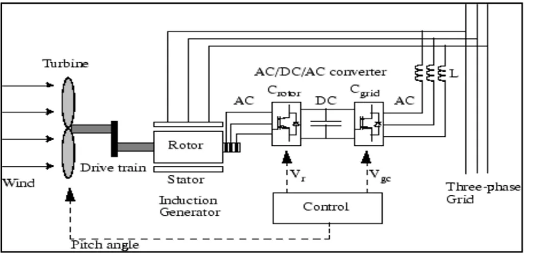
2.3.1.3 Doubly-fed induction generator (DFIG)
The doubly fed induction generator (DFIG) (Figure 2.6) is generally a type of wound rotor induction generator (WRIG) presented in Figure 2.6. The AC/DC/AC converter is divided into two parts: the rotor side converter (Crotor) and another is grid side converter (Cgrid). In
IGBT, Crotor and Cgrid are voltage source that is used to generate an AC voltage from a DC
voltage source. A capacitor bank is connected to the DC side to act as a DC voltage source. The inductance L is used to connect Cgrid to the power grid. The windings of the three-phase
rotor are connected to the Crotor by using rings and brushes. Three-phase stator windings are
connected directly to the grid. The power from the turbine is converted into electrical energy by using induction generator and it dispatched to the network by the rotor and stator windings. The control system produces pitch angle control and the control signals of the voltage Vr and Vgc for the Crotor and Cgrid respectively in order to control the power of wind
turbine, the DC voltage, and the reactive power. Matlab (2017).
Figure 2.6 Operating Principle of the Doubly-Fed Induction Generator Adapted from Matlab (2017)
Figure 2.7 shows the operating mode and the power flow between the power grid and the wind turbine through the generator and the converter. In super-synchronous speed operation, rotor power, when Pr is positive; the power is transmitted from the rotor to the network
through the converter. The Mechanical rotational speed is higher than the synchronous speed (ωr> ωs and s <0). With s: slip of the ASM: s r
s
s ω ω
ω
− =
In super-synchronous speed operation, when Pr is negative; power is transmitted from the
network to the rotor through the converter. The mechanical speed is comparably less than the synchronous speed (ωr <ωs and s> 0). The converters can provide up to 25% of the rated
power of the DFIG.
In both cases the stator power, Ps supplied to the network and the absolute value of s is less
than 1.
Figure 2.7 Power Flow of DFIG Adapted from Matlab (2017)
Mechanical power to the stator and the output electric power are expressed as follows:
m m r s em s P T P T ω ω = = (2.1)
The dynamics equation of the machine is: r m em d J T T dt ω = − (2.2) At the equilibrium: Tm = Tem and Pm = Ps + Pr (2.3)
The power is controlled to follow a preset adjustment curve. An example is shown in Figure 2.8
Figure 2.8 Adjusting power characteristic for a DFIG Adapted from Matlab (2017)
The actual speed ωr of the turbine is measured and the corresponding mechanical power is
Where:
Pm Mechanical power generated by the wind turbine and transmitted to the rotor
Ps Stator electrical power output
Pr Rotor electrical power output
Pgc Cgrid electrical power output
Qs Stator reactive power output
Qr Rotor reactive power output
Qgc Cgrid reactive power output
Tm Mechanical torque applied to rotor
Tem Electromagnetic torque applied to the rotor by the generator
ωr Rotational speed of the rotor
ωs Rotational speed of the magnetic flux in the air-gap of the generator, this speed is
named synchronous speed. It is proportional to the frequency of the grid voltage and to the number of generator poles.
J Combined rotor and wind turbine inertia coefficient
There are five stages of operation of a DFIG wind turbine are defined by the control curve (Figure 2.8):
• Between 0 m/s velocity and A. The starting phase of the machine: electrical generation begins when the mechanical speed reaches about 70% of the synchronous speed of the generator but the electric power remains low;
• Between A and B the line is straight, the velocity of point B should be higher than the velocity of point A;
• Between B and C: The extraction phase of the maximum power, mechanical speed varies and can reach a value close to the rated speed and the electric power increases rapidly. The setting of blades angle β remains at its minimum value in order to obtain a maximum power coefficient. The maximum power is then obtained for each value of the mechanical speed and for the average wind speeds;