ADAPTIVE SWITCHED BEAM RECONFIGURABLE ANTENNA FOR WIRELESS SENSOR NETWORK APPLICATIONS.
MÉMOIRE PRÉSENTÉ
COMME EXIGENCE PARTIELLE DE LA MAÎTRISE EN INGÉNIERIE
Par
MUKENDI LEINGTHONE MUAMBA
Jury d'évaluation
Examinateur Externe : Prof. Gilles Y. Delisle, Université Laval Examinateur Externe : Prof. Michel Misson, Université Clermont Auvergne
Examinateur Interne : Prof. Nahi Kandi!, Université du Québec en Abitibi-Témiscamingue
Directeur de Recherche : Prof. Nadir Hakem, Université du Québec en Abitibi-Témiscamingue
Mise en garde
La bibliothèque du Cégep de l’Témiscamingue et de l’Université du Québec en Abitibi-Témiscamingue a obtenu l’autorisation de l’auteur de ce document afin de diffuser, dans un but non lucratif, une copie de son œuvre dans Depositum, site d’archives numériques, gratuit et accessible à tous.
L’auteur conserve néanmoins ses droits de propriété intellectuelle, dont son droit d’auteur, sur cette œuvre. Il est donc interdit de reproduire ou de publier en totalité ou en partie ce document sans l’autorisation de l’auteur.
Warning
The library of the Cégep de l’Témiscamingue and the Université du Québec en Abitibi-Témiscamingue obtained the permission of the author to use a copy of this document for non-profit purposes in order to put it in the open archives Depositum, which is free and accessible to all.
The author retains ownership of the copyright on this document. Neither the whole document, nor substantial extracts from it, may be printed or otherwise reproduced without the author's permission.
BIBLI
THÈQUE
Cégep
de I'Abitibi-Témiscamingue
Université
du Québec en Abitibi-Témiscamingue
Mise en garde
La bibliothèque du Cégep de l' Témiscamingue et de l'Université du Québec en Abitibi-Témiscamingue a obtenu l'autorisation de l'auteur de ce document afin de diffuser, dans un but non lucratif, une copie de son œuvre dans Depositum, site d'archives numériques, gratuit et accessible à tous.
L'auteur conserve néanmoins ses droits de propriété intellectuelle, dont son droit d'auteur, sur cette œuvre. Il est donc interdit de reproduire ou de publier en totalité ou en partie ce document sans l'autorisation de l'auteur.
Warning
The library of the Cégep de I'Témiscamingue and the Université du Québec en Abitibi-Témiscamingue obtained the permission of the author ta use a copy of this document for non-profit purposes in arder ta put it in the open archives Depositum, which is free and accessible ta ali.
The author retains ownership of the copyright on this document. Neither the who le document, nor substantial extracts from it, may be printed or otherwise reproduced without the author's permission.
ABSTRACT
The ability to tune resonances, change polarization and modify their radiation patterns has made reconfigurable antennas development imperative in modern telecommunication systems and they are widely used as additional features in wireless communication system. Their agility and diversity have expanded their horizons for different types of applications especially in cognitive radio, satellites and many other applications. Reconfigurable antennas satisfy the requirements for increased functionality, such as direction finding, bearn steering, radar, control and command, within a confined volume.
The integrations of reconfigurable antennas with radio frequency (RF) switches are needed to perform the switchable ability among many other reconfiguration techniques.
In this project, a new reconfigurable Frequency Selective Surface (FSS) screen 1s proposed to create a switched bearn reconfigurable antennas. Indeed, the transmission/reflection responses of each planar FSS are carefully delineated to elaborately reshape the screens to a cylindrical form. The cylindrical shape is deliberately chosen to achieve the desired sweeping bearn performances over ali azimuth angles. Then, by precisely controlling the active elements integrated into the cylindrical FSS, the radiated field of an RF-source at the center of the cylinder is controlled to achieve the desired functionality.
Validation for Adaptive Switched Bearn Reconfigurable Antenna (ASBRA) is achieved by comparing the simulated and measured radiation patterns parameters. The measured half-power bearn width is 72° while 40° for the simulated. The simulated realized gain is around 15 dB while the measured gain is around 12.5 dBi at the frequency range of2.4GHz.
ABSTRACT
La possibilité de syntoniser les résonances, de modifier la polarisation et de modifier leurs diagrammes de rayonnement a rendu impératif le développement d'antennes reconfigurables dans les systèmes de télécommunication modernes et elles sont largement utilisées en tant que fonctionnalités supplémentaires dans les systèmes de communication sans fil. Leur agilité et leur diversité ont élargi leurs horizons pour différents types d'applications, en particulier dans les domaines de la radio cognitive, des satellites et de nombreuses autres applications. Les antennes reconfigurables répondent aux exigences d'une fonctionnalité accrue, telles que la direction, la direction du faisceau, le radar, le contrôle et la commande, dans un volume confiné.
Dans ce projet, nous proposons de créer de nouveaux écrans reconfigurables à surface sélective en fréquences (FSS) pour créer des antennes reconfigurables à faisceaux commutés. En effet, les réponses de transmission 1 réflexion de chaque FSS planaire sont soigneusement délimitées pour remodeler minutieusement les écrans en une forme cylindrique. La forme cylindrique est délibérément choisie pour obtenir les performances de balayage souhaitées sur tous les angles d'azimut. Ensuite, en contrôlant avec précision les éléments actifs intégrés dans le FSS cylindrique, le champ rayonné d'une source RF au centre du cylindre est commandé pour obtenir la fonctionnalité désirée.
La validation de l'antenne reconfigurable à faisceau commuté est obtenue en comparant les paramètres des diagrammes de rayonnement simulés et mesurés. La largeur de faisceau mesurée est de 72
°
alors qu'elle est de 40°
pour la simulation. Le gain simulé réalisé est d'environ 15 dB et le gain mesuré est d'environ 12,5 dBi dans la gamme de fréquences de 2,4GHz.ACKNOWLEDGEMENT
Specially dedicated to my beloved ones who always inspired and motivated me along my excellent journey of education
To Almighty God who was, is and is to come for his kindly love towards . 'Yahweh Jirreh my provider'
Specially my gratefulness and appreciation goes to my project supervisor Professor Dr. Nadir Hakem, for welcoming me to his research team, for his confidence during the entire
thesis, for his guidance, motivations, support and constructive comments in accomplishing this project;
'I say Thank y ou so very much Professor.'
I gratefully acknowledge my thesis committee members Professor Gilles De/isle, Professor Nahi Kandi/ and Professeur Michel Misson for their insights, remarks and suggestions on my dissertation on this research, which will be a valuable experience for
my future career.
I would like to thank the engineer of the LRTCS laboratory, Mr. Mohamed Ailas, for realization of the experimental prototype.
I thank as weil my thesis advisors Taieb El karkraoui and Alex M oua pi Researchers at the UQAT and Joseph Kabuya and Iris Kapinga researchers at Laval university for their
My precious Parents
Mukendi Tubongo Louis and Justine Kenda
My Wife 'baby douce' JessicaMalila and my beautiful Children Lincah, Beracah and Akilimali
'For your understanding, patience and supports through this period oftime. Without your ki nd cares and patience, the diffzculties of my master objectives and beingfar from of
family would never be endured' My awesome brothers
Cyrille Mukendi & Des anges Mas hat a, André Mukendi & Cathy Meta and Joseph Kabuya & Iris Kapinga
My lovely sisters
Claudine Ngalula & Seraphin Mulumba, Prisca Ntumba & Serge Cimanga
Rosie Ngoya & Hyppolite Salambua My wonderful Parents in law
Christophe Tshimpe Ditumbule and Perpetue Mali la Muenyi My brothers in law
Christian Tshimpe & Christelle, Thierry Tshimpe, Steve Tshimpe and Nicky Tshimpe. My Sisters in law
Patricia Tshimpe & JeffMuzingu, Vanessa Tshimpe & BillyMwepu, Laetitia Tshimpe &
Linné Nkongolo. My nephews and nieces
Eli Énoch, Pi ris, Joris, Johann, Percy, Joyce, Elroy, Brian, Kenny, Gradi, Ariella, Daniella, Paris, Prunelle, Elmer, Nehema and Damaris
MyPastor
Pierre Paradis & Linda Lacoste. My Best Friends
Francis Royer & Katy Lacoste, Sylvain Lacoste & Melanie Guay.
"We don 't remember days, but we remember moments"
TABLE OF CONTENTS
ACKNOWLEDGMENTS ... i
ABSTRACT. ... ii
TABLE OF CONTENTS ... v
LIST OF FIGURES ... ix
LIST OF TABLES ... xiii
LIST OF ABBREVIATIONS ... xiv
LIST OF SYMBOLS ... xv
LIST OF APPENDICES ... xvi
1. CHAPTER ONE: GENERAL INTRODUCTION ... ! 1.1 Proj ect background ... 1
1.2 Motivation ... ! 1.3 State of the Art ofWireless Sensor Network ... 2
1.3.1 Definition of WSN ... 2
1.3.2 Architecture of sensor node ... 3
1.3.3 Protocols ... 5 1.3.4 Deployment ... 6 1.3.5 Scalability ... 6 1.3.6 Power consumption ... 7 1.3. 7 Applications of WSN ... 8 1.4 Problem identification ... 9 1.4.1 Introduction ... 9
1.4.2 Technical and organizational challenges ... 10
1.4.2.1 Shape ofbeam ... 10
1.4.2.2 Choice of structure ... Il 1.4.2.3 Switching mode ... 11
1.4.2.4 Power source ... li 1. 5 Problem remedies and project objectives ... 12
1. 5.1 Main objectives ... 12
1.5.2 Specifies objectives ... l2 1.6 Organization of the thesis and original contribution ... l2 1.6.1 Scope and limitation of the project.. ... l2 1.6.2 Thesis organization ... 13
2. CHAPTER 2: FUNDAMENTAL KNOWLEDGE OF RECONFIGURABLE
ANTENNAS ... 15
2.1 State of the art on antenna ... 15
2.1.1 Type of antenna ... 16
2.1.1.1 Wire antennas ... l6 2.1.1.2 Aperture antennas ... 16
2.1.1.3 Array antennas ... 16
2.1.1.4 Printed antennas ... 16
2.1.2 Fundamental antenna parameters ... l7 2.1.2.1 Bandwidth ... 17
2.1.2.2 S-parameters ... 18
2.1.2.3 Radiation pattern ... l9 2.1.2.3.1 Antenna field region ... 20
2.1.2.3.2 Reactive near-field region ... 21
2.1.2.3.3 Radiating near-field or Fresnel region ... 21
2.1.2.3.4 Radiating far-field or Fraunhofer region ... 21
2.1.2.3.5 Characteristic impedance ofEM waves ... 22
2.1.2.4 V elocity of propagation ... 22
2.1.2.5 Directivity ... 23
2.1.2.6 Antenna efficiency ... 23
2.1.2.7 Gain ... 24
2.1.2.8 Polarization ... 24
2.1.2.9 Half power bearn width ... 25
2.2 Reconfigurable antenna ... 26
2.2.1 Introduction ... 26
2.2.1.1 Frequency reconfigurable antenna ... 27
2.2.1.2 Polarization reconfigurable antenna ... 28
2.2.1.3 Radiation pattern reconfigurable Antenna ... 29
2.2.2 Principles of reconfigurability and RF switch technologies ... 29
2.2.2.1 Reconfiguration by switching ... .30
2.2.2.1.1 Electrically reconfigurable antenna ... .30
2.2.2.1.2 RF- MEMS ... .30
2.2.2.1.3 V aractors ... .31
2.2.2.2 Reconfigurability by changing material... ... .33
2.2.2.2.1 Tunable conductivity ... .33
2.2.2.2.2 Tunable permittivity ... .33
2.2.2.2.3 Tunable permeability ... .34
2.2.2.3 Optically reconfigurable antennas ... .34
2.2.2.4 Reconfiguration by structural alteration ... .34
2. 2.3 Comparison between different techniques and practical issues ... .3 5 2.3 Propagation channel.. ... .36
2.3.1 Propagation in free space ... .37
2.3.2 Multipath propagation ... .38
2.4 Summary ... .38
3. CHAPTER THREE: A REVIEW OF RECONFIGURABLE ANTENNA BASED ON FSS ... 39
3.1 Introduction ... .39
3.2 Periodic structures ... .39
3.2.1 Analysis ofperiodic structures ... .40
3.2.1.1 Structure EBG ... .40
3.2.1.1.1 Historie on periodic structure ... .40
3.2.1.2 Theoretical notion ... .42
3.2.1.2.1 Floquet's-Bloch's mode ... .42
3.2.1.2.2 Dispersion diagram or Brillouin diagram ... .43
3.2.1.2.3 Fabry perrot resonator ... .48
3.2.2 Structure EBG ... .49
3.2.3 Structure FSS ... 50
3.2.3.1 Passive periodic structure ... 52
3.2.3.1.1 Continuons band FSS structure ... 52
3.2.3.1.2 Discontinuons band FSS structure ... 54
3.2.4 Active FSS structure ... 55
4. CHAPTER FOUR: DESIGN AND FABRICATION PROCESS OF THE ASBRA ... 58
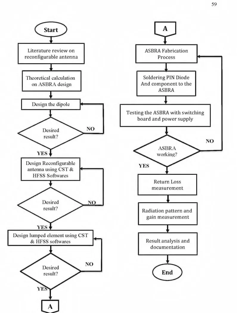
4.1 Project methodology ... 58
4.2 Cylindrical FSS screen ... 60
4.2.2 Source of radiation design ... 62
4.2.3 FSS Unit ce li design ... 64
4.2.4 PIN diode integration ... 65
4.2.4.1 PIN diode representation using lumped element ... 65
4.2.4.2 PIN diode representation using PEC pad ... 66
4.3 Parametric study of ASBRA ... 67
4.3.1 Effect of the radius of the cylindrical reflector. ... 68
4.3.2 Effect of the number ofFSS unit cell elements ... 71
4.3.3 Effect of the width ofFSS Elements ... 72
4.3.4 Effect ofthe band gap aperture ... 73
4.3.5 Effect oflumped elements ... 74
4.3.6 Effect of the opening angle ... 76
4. 4 Antenna matching ... 81
4.5 Fabrication process ... 83
4.6 Measurement process ... 86
4. 6.1 Return loss measurement ... 86
4.6.2 Radiation pattern measurement ... 88
4.7 Summary ... 91
5. CHAPTER FIVE: RESULTS ANALYSIS AND DISCUSSION ... 93
5.1 Introduction ... 93
5.2 Analysis and discussion of the ASBRA. ... 93
5.2.1 Input return loss ... 93
5.2.2 Realized gain ... 95
6. CHAPTER SIX: CONCLUSION ... 98
6.1 Conclusion ... 98 6.1.1 Key contribution ... 99 6.1.2 Future Research ... 99 7. REFERENCES ... 100 8. PUBLICATIONS ... 110 9. APPENDICES ... 112
LIST OF FIGURES
Figure 1.1 Wireless Sensor Network ... 3
Figure 1.2 Physical architecture of sens or node ... 3
Figure 1.3 Commercial WSN nodes ... 5
a. MICA2 Dot ... 5
b. Waspmote plug & sensor. ... S Figure 1.4 Power consumption of a MICAz node ... 7
Figure 1.5 Antenna bearn patterns in switched bearn systems ... ll Figure 2.1 Two port network definition ... 19
Figure 2.2 Coordinate system for antenna analysis ... 20
Figure 2.3 Field regions of an antenna ... 21
Figure 2.4 Rotation of a plane electromagnetic wave at z ~ 0 as a function oftime ... 25
Figure 2.5 Two-dimensional of power pattern ... 26
Figure 2.6 The block diagram of the reconfigurable antenna ... 27
Figure 2. 7 Telecommunication infrastructure ... 28
Figure 2.8 Types ofRF-MEMS switches ... 30
Figure 2.9 (a) Electrical Equivalent Circuit, (b) Symbol ofVaractor diode ... 31
Figure 2.10 Intrinsic region ofthe Pin diode ... 32
Figure 2.11 The principle of a crystalline solar cell ... 33
Figure 3.1 Structure Yablonovite ... 41
Figure 3.2 Structure woodpile ... 41
Figure 3.3 One-dimensional periodic structure ... 42
Figure 3.4 Surface wave dispersion pattern of metal strips ... 44
Figure 3.5 Two-dimensional crystalline structure ... 46
Figure 3.6 (a) Centered cubic cell. (b) Wigner-Zeitez cell ... 47
Figure 3.7 Fabry-Perot cavity ... 48
Figure 3.8 Resonant cavity ... 48
Figure 3.9 EBG antenna of Temelkuran ... 49
Figure 3.11 EBG Lens antenna ... 50
Figure 3.12 High impedance surface: (a) Mushroom cell, (b) Comb teeth ... 51
Figure 3.13 Artificial magnetic wall... ... 52
Figure 3.14 Periodic continuous strip structure ... 53
Figure 3.15 Electrical model of a continuous band structure ... 54
Figure 3.16 Periodic structure with discontinuous bands ... 54
Figure 3.17 Electrical model of a discontinuous strip structure ... 55
Figure 3.18 Active FSS Structure ... 56
Figure 4.1 Flow chart of overall process of the ASBRA. ... 59
Figure 4.2 Geometry of the proposed cylindrical FSS antenna ... 60
Figure 4.3 Geometry of a corner reflector into a semi-cylindrical reflector. ... 61
Figure 4.4(a) Frequency response of the dipole ... 62
Figure 4.4(b) realized gain response of the dipole ... 63
Figure 4.4(c) Radiation pattern response of the dipole ... 63
Figure 4.4(d) Radiation pattern of the di pole in azimuth plane ... 63
Figure 4.5 Fss Unit cell of the Reconfigurable Bearn Switching antenna ... 64
Figure 4.6(a) ASBRA representation using lumped element in CST. ... 65
Figure 4.6(b) Pin diode electrical model (a)RLC-Serial (b) RLC-Parallel... ... 65
Figure 4.6( c) Lumped element circuits that are developed in CST software ... 66
Figure 4. 7 ASBRA representation in CST using PEC pad ... 66
Figure 4.8(a) Effect of the radius R on the resonance frequency of the cavity ... 69
Figure 4.8(b) Effect of the radius R on the H-plane radiation pattern of the cavity ... 69
Figure 4.8(b) Effect of the radius R on the H-plane radiation pattern of the cavity ... 70
Figure 4.8(c) Effect of the radius R on the E-plane radiation pattern of the cavity ... 70
Figure 4.9 Effect of the number ofFSS elements (NFSS~6,9,12,15) ... 71
Figure 4.11 Effect of the width of the gap ... 73
Figure 4.12 Effect of the diode capacitance on the structure ... 74
Figure 4.13 Effect of the diode capacitance on the radiation pattern ... 75
Figure 4.14 Effect of the capacitance on directivity ... 75
Figure 4.15 Opening angle ofthe radiating structure ... 75
Figure 4.16 Radiation diagrams in the azimuth plane at 2.45 GHz ... 76
Figure 4.17 Normalized radiation diagrams in the E- plane at 2.45 GHz ... 76
Figure 4.18 Directivity according to the opening angle ... 77
Figure 4.19 S 11 according to the opening angle ... 77
Figure 4.20 Radiation pattern according to the opening angle ... 78
Figure 4.21 Switching bearn in the all azimuth angles ... 78
Figure 4.22 Reconfiguration in the H-plane ... 79
Figure 4.23 Realized gain of the ASBRA ... 80
Figure 4.24 ASBRA radiation pattern in CST.. ... 81
Figure 4.25 Matching circuit ... 81
Figure 4.26 Return loss without and with matching circuit ... 82
Figure 4.27 Realized gain without and with matching circuit. ... 82
Figure 4.28 VectorStar MS4647 A VNA Front Panel- Rear panel... ... 85
Figure 4.29 Measuring the S 11 of the di pole alone ... 86
Figure 4.30 Measuring the S 11 of overall structure ... 87
Figure 4.31 Power received and radiation pattern measurement set-up ... 87
Figure 4.32 LNA RLNAOlMlOG ... 88
Figure 4.33 Anritsu MG3692B ... 88
Figure 4.34 The Lab-volt 9506-00 ... 89
Figure 4.35 The Lab-volt 9506-00 setup in the Laboratory ... 89
Figure 5.2 Realized gain results for measured and simulated ASBRA. ... 94
Figure 5.3 Measuring the di pole alone ... 94
Figure 5.4 Measuring the ali structure ... 95
Figure 5.5 Radiation pattern of the dipole ... 96
Figure 5.6 Radiation pattern of the simulated and the fabricated ASBRA ... 97
Table 1.1 Commercial WSN node specifications ... 5
Table 2.1 Comparison between different switches ... 36
Table 4.1 The value oflumped elements as a PIN diode ... 66
Table 4.2 LNA Parameters RLNAOlMlOG ... 89
Table 4.6 Steps of fabrication process ... 84
Table 5.1 Comparison ofbandwidth between simulation and measurement ... 94
Table 5.2 Previous researches on reconfigurable antenna ... 98
ASBRA - Adaptive Switched Bearn Reconfigurable Antenna WLAN- Wireless Local Area Network
UWB - Ultra Wide Band CR- Cognitive Radio
VSWR- Voltage Standing Wave Ratio RL - Return Loss
BW- Bandwidth
HPBW- HalfPower Bandwidth FR-4- Fire Retardant Type 4 FSS - Frequency Selective Surface GHz - Gigahertz
UV -Ultra-Violet
CST - Computer Simulation Technology EM - Electromagnetic
SNR- Signal Noise Ratio
GSM - Global System for Mobile Communications WIFI - Wlreless Fldelity
RF - Radio Frequency
MEMS - Micro Electro Mechanical Systems PBG- Photonic Band Gap
EBG- Electromagnetic Band Gap LHM - Left Hand Material
TEM - Transverse ElectroMagnetic TE - Transverse Electrique
TM - Transverse Magnétique QoS - Quality of Service MAC - Media Access Control
HART- Highway Addressable Remote Transducer Protocol UA V- Unmanned Aerial Vehicles
FP- Fabry-Pérot
fi -
Low frequency fh - High frequency r-Scaling factor E- Electric field. H- Magnetic field. h - Substrate thickness. t -Copper thicknesssr - Relative permittivity of material. tan i5 - Tangentialloss of material. dB- Decibel
mm -millimeter
R- Resistor
L- Inductor
C - Capacitor
r
-the reflection coefficient. VO - reflected voltage wavevo+ -
incident voltage waveCHAPTERONE
GENERAL INTRODUCTION
1.1. Proj ect background
The field of telecommunications 1s m perpetuai evolution and the dynamics of development are constantly needed to improve flexibility, ergonomies and speed of information transfer. Therefore, wireless communication is essential for severa! reasons such as security, location and productivity.
The unsupervised or random deployment of a wireless sensor network requires the installation of an antenna system capable of adapting itselfto the context of the conditions of propagation of the wireless signal. By adapting the ir operating characteristics such as the radiation pattern and by altering the current flow using switching elements such as Pin-diodes, the reconfigurable antennas have the ability to desirably improve energy efficiency and to avoid the effects of interference and multi-channel discoloration effects. Thus, the introduction of a reconfigurable antenna instead of an omnidirectional antenna makes it possible to transmit or receive the radio signal with longer ranges and faster throughput while reducing the amount of energy required establishing communication at its minimum. This project proposes the design and development of an adaptive narrow band antenna using FSS technic with the integration of the PIN-diode to form the switched bearn reconfigurable antenna. Depending on the switching state, the ASBRA enables the selection between severa! beams and achieves the desired performance that allows reconfigurable directive beams over the entire azimuth plane with equidistant angles. This thesis describes the ASBRA's development including the literature review, the simulation design until the fabrication and measurement process.
1.2. Motivation
N owadays, the importance of communication in an emergency response scenario is weil known due to the frequency of recent incidents such as disasters and their wide range of sever impact throughout the world. Human civilization has always been devastated by natural disasters, such as earthquakes, volcanoes, tsunamis, landslides, floods, forest fires, weather and climatic conditions (irma, harvey, hurricanes , tornadoes, extreme heat or co id, etc.) or artificial disasters such as large-scale terrorism, chemical spills, nuclear radiation
eruptions, public service failures, epidemies, accidents, explosions and urban fires, etc .... which is a serions disruption to the functioning of a community or society. Such emergencies require a rapid and effective response from varions stakeholders (team of pumps, firemen, paramedics, doctors ... ) responsible for intervening in the sectors concerned; So it allows us to anticipate our actions.
One of the most important components to help respond to these emergencies is the antenna. It must be selective in the sense that it must correspond to the frequency band given in a particular direction to send the most possible information, to reduce collisions, increase communication distance and optimize power consumption; It must also be economical in the sense that its output must be as ideal as possible in terms of efficiency and gain which leads to smart antenna in the literai sense of the term. As a result, intensive research has been conducted in many directions to find other alternatives and approaches in this field. One of these alternatives is to use a FSS in reconfigurable antennas. This approach offers more features for an antenna, more versatility, Jess cost and significant savings in size and space [1, 2]. So research in this area is very important and is one of the most popular areas nowadays. Our motivation is to investigate a new FSS structure with the use of RF switch technology to actively and intelligently change the operating bearn of an antenna including minimization of active switching components and an overall reduction in antenna design complexity.
1.3. State of the Art ofWireless Sensor Network 1.3.1. Definitions of Wireless Sensor Network
A sensor is a small autonomous deviee capable of performing simple measures on its immediate environment. WSN are a new class of distributed systems [3] that consists of dispersed group of deviees which use sensors to monitor environmental conditions. WSN were originally designed to facilitate military operations, but their applications have since grown to cover severa! domains such as medical, industrial and, more recently, home networks. Although this development was initially fueled by military research areas, today, as recent technological advances, the possibility of producing low-cost sensors has increased considerably, which brings us to the challenge of scaling networks to a larger number of nodes. As shown in Figure 1.1, WSN is a group of very small deviees, named node, varying from dozens elements to severa! thousands.
Weother
Oatabaae
Figure 1.1 Wireless Sensor Network. [3]
Acrnotc CompUtlft9
Aca.sourccs
In these networks, every node is capable of watching its environment and reacting if necessary by sending the infonnation collected with the aid of wireless connection in one or several points of collection (Sink Puits). According to the system, nodes can communicate directly with the Puits Sink, or then act as relay for the transmission of information.
1.3 .2. Architecture of a sens or node
According to [4], a genera.lized diagram of a WSN architecture is presented. The authors divide the architecture into four major core units as shown in figure 1.2.
Figure 1.2 Physica!Architecture of a sensor node [4] It is possible to distinguish:
• A Sensing unit or Capture unit: it is the interface to the physical world responsible for carrying out data acquisition which provide the means to gather and send physica.l quantities and are converted by analog to digital converters to be analyzed and processed by the processing unit;
• A processing unit: this is the processorthat is responsible for processing ali relevant data and executing the code that describes the behavior of the sens or node; frequent! y known as micro-processor, this unit is responsible for controlling the other units' functionalities. However, it may also contain memory and severa! inputs/outputs, bence, it alternative title of micro-controller
• A Transceiver unit or Communication unit: it is composed of a (radio module) transmitter/receiver antenna(s) allowing communication between the different nodes of the network.
• A Power unit or unit of energy: this is responsible for maintaining the electric activity of the sensor node. This may be achieved by a network ce li or by recharging a battery via energy harvesting, such as solar energy with solar ce lis.
• Location fmding system: Used to determine the location of the sensor with high accuracy.
• Mobilizer: This is responsible to move the sensor node when it is required to carry out the task
The first important requirements ofWSN is the node's lifetime, the network should be power efficient and fulfill its task as long as possible. The energy savings cau be obtained from the optimization of software or hardware used on the system. U sing energy harvesting from the environment is also a good solution to increase the WSN lifetime. Besides, the WSN should be based on low cost deviees because the number of node can be up to thousands or more. Sensor network should be very flexible to adapt to the different conditions and scalable to support large number of nodes.
The system should be self-reconfigured to guarantee the network connection when the failure of individual nodes occurs. The reprogramming of sensor nodes is also important to update the new configuration and improve the performance of system. Finally, a sensor network should be able protect itself and its data. For the secure data transmission, the encryption keys have to be established among sensor nodes.
There are many different types of sens ors that are used on WSN such as:
Temperature, Humidity, V ehicular movement, Lightning condition, Pressure, Soi! makeup, Noise leve!, The existence of certain kinds of objects, Mechanical stress levels, The current characteristics such as speed, direction, and size of an object.
In [4], I.F. Akyildiz et al. categorized the WSN application into military, environment, health, home and other commercial areas. In addition, space exploration, chemical processing and disaster relief are also considered as the expanding categories.
Several wireless sensor network commercial solutions are listed below: Platform
MICA Educational 8-16 MHz 4kB 2.4 - 2.48 GHz 38.4/250 kB/s LOTUS Industrial 10-100 MHz 64kB 2.4 GHz ISM 250 kB/s
TelosB Educational 8MHz 10 kB 2.4 - 2.48 GHz 250 kB/s
IRIS OEM Edition 8MHz 8kB 2.4 GHz ISM 250 kB/s
LOTUS Industrial 8MHz 4kB 433 MHz ISM 250 kB/s
Waspmote Versatile 14.7 MHz 8kB 2.4 GHz ISM 250 kB/s
Table 1.1: Commercial WSN node specifications. Adapted from [3].
(a) AIJICA2 Dot. (b) Waspmote Plug & Sensor Figure 1.3 Commercial WSN nades [3].
1.3.3. Protocols
As WSN evolved, several key factors such as robustness, efficiency and reliability arose to challenge the QoS. As these factors require mass expertise in all fronts of networking stack, from physical radio design to channel access schemes, routing protocols, and distributed data-processing algorithms [5], the IEEE introduced in 2003 a standard which specifies physicallayer and MAC. The major features of IEEE 802.15.4 standard rely upon specifications in the physical and MAC layers for low-rate nearby conmmnications. The standard de fines, among others, which the se networks should be capable of pro vi ding up to
250 kbps of data transfer rate with simple QoS requirements. The reason why this standard uses low transmission rates is because sensor network applications do not usually need high data transfer rates and consequently would clearly benefit from low-power solutions to prolong the lifetime. The list below briefly reviews the solutions that are based on the 802.15.4 standard:
1. ZigBee
2. Wireless HART (Highway Addressable Remote Transducer Protocol) 3. 6Lo WP AN (IPv6 over Low power wireless persona! area network)
Most commercial WSN solutions use one ofthese three standards. However, each may be better suited for a particular application. For instance, ZigBee networks are targeted for home automation, smart energy, building automation, telecommunication services and health care while Wireless HART is suited for automation and industrial applications. 1.3.4. Deployment
With the increasing number of nodes deployed in WSN infrastructures, the ability to collect sensor information has been part of a strate gy to succeed in real-world applications. This not only reduces the overall costs, but can also pro long network lifetime. According to [6], node deployment can be classified as:
• Static dep1oyment: nodes remain static during the network lifetime. This method may be sub classified as either controlled or random deployment [7]. The mentioned reference also exposes demonstrate optimization goals for this node deployment method such as: area coverage, network connectivity, network lifetime, and data fidelity. • Dynamic dep1oyment: nodes may re-arrange their position due to application-leve!
requires location changes.
For instance, authors in [8] present design strategies of using Unmanned Aerial Vehicles UA Vs to deploy wireless sensor networks for post-disaster monitoring, which perfectly exemplifies the random-static deployment mentioned above. As referred to earlier, the interest consists in network for agriculture, and for this reason a controlled-static" deployment is used in order to optimize the performance of the network.
1.3.5. Scalability
Wireless sens or networks may grow to contain hundreds of nodes; this creates scalability necessitate in-place routing protocols for managing and controlling scalable and adaptive networks. Severa! routing protocols, studied in [9] and [10] addresses these problems and
assesses those which are the best routing protocols using quantitative metrics such as throughput, latency, energy consumption, and delay.
1.3.6. Power consumption
As referred to earlier, the power unit is a key element in the WSN node structure. However, it is also the princip le time limiting factor in the lifetime of a network. Currently, batteries are the major source of energy in WSNs and/or power buffer, in the case of energy harvesting WSN nodes. In [11], the authors show the different energy sources suitable for scavenging, energy conversion deviees and a wide comparison of practical energy harvesting deviees such as vibration based or solar based deviees. In fact, in the WSN of interest, solar energy scavenging is used with a solar ce li module.
The greatest part of the power is spent by peripherals, specifically radio modules, as figure. 1.4 illustrates. 75 §;'
60-s
1-<45-~
p., 30-15 Sensor MCU Radio ---,', ,--- - ,---''
, TX RX Idle Sleep , ~, __________________________________ ;~Figure 1.4 Power consumption of a MICAz node [11].
Currently, solutions to overcome this problem are based on batteries which may, in the case of nodes failure in a low density network, be quickly drained.
Dynamic Voltage Scaling in another processing power-saving technique. It adapts the power supply voltage and clock frequency of the microprocessor which depends upon the workload, leading to lower energy consumption without affecting the overall performance. 1.3. 7. Application of Wireless sens or network
The sensor arrays can be made up of different types of sensors depending on the application. In general, the main applications of wireless sens or networks can be military, environmental, sanitary or domestic [12].
• The military field is the first to be interested in the WSNs, in order to study the
movements of the enemy troops, orto analyze a battlefield before embarking on it. However, due to application-leve! requirements, robustness, scalable self-organization, network connectivity, energy consumption, fault tolerance, and end-to-end message security are the major concerns. These type ofWSNs can be applied in three military operation scenarios:
o battlefield: large-scale and non-manually deployed;
o urban-warfare and force-protection: medium-scale and manually deployed; o other-than-war: any scale, both manually or non-manually deployed.
In [13], a battlefield scenario requesting distribution ofthousands oftactical sensors in a specifie area using UA V dropping and/or artillery deployment methods is presented. It has a self-organizing initialization period and after that the information is reported to a UAV sink node. Also [14] report, among others, severa! examples of military WSN applications such as perimeter protection, sniper detection and localization," chemical, biological and explosive vapor detection with micro cantilever array sensors". [15]
• In the environmental field, the WSN s are used to detect and pre vent natural
disasters such as fires, to understand the evolution of natural habitats and movements of animal populations with a view to knowledge and protection of species or in agricultural environments to optimize soi! management. The most commonly used sens ors are:
0 Atmospheric pressure sensor 0 Leaf wetness sens or
0 Humidity sensor 0 Temperature sensor 0 Luminosity sensor 0 Soi! moisture sensor 0 Soi! temperature sensor
o Ultraviolet radiation sensor o Anemometer
o Pluviometer
o Dielectric permittivity sensor
• In the biomedical field, the implantation of autonomous sensors in the human
body or in the habitat would enable the physiological data to be collected and stored continuously and sent to a competent medical center, distance of a convalescent patient,
or facilitating earl y diagnosis and disease prevention. In the case of human applications, WSNs are applied in hospitals and homes.
Severa! applications are listed below. o emergency response
o provision of interfaces for the disabled o integrated patient monitoring
o drug administration
o tracking and monitoring doctors and patients in hospitals o Sudden Infant Death Syndrome (SIDS) detection
o premature infant thermal regulation
• Finally, WSNs are also useful in monitoring difficult or structural environments such as bridges, vehicles or industrial environments for the purpose of detecting alterations and preventing disasters which is part of our work.
The industrial applications can be divided based on specifie production requirements. o Industrial environmental sensing: pollution, hazard, security
o Condition monitoring: structural health, equipment condition, human error monitoring
o Process automation: evaluation, improvement
1.4. Problem identification 1.4.1. Introduction
Antenna development play a key role in wireless technology since the rapidly increasing number of users in broadcasting, telecommunications, navigation, radar, sensors, military and for wireless communication. The increasing number ofusers may lead to congestion of existing spectrum such as Wireless Local Area network (WLAN). Most WLANs use the same frequency band in the narrow range of 2.4 to 2.5 GHz. They link many systems together, thus resulting in better communication and compatibility. In addition, most of these systems use the miniature sleeve dipole antenna. Although the use ofthese antennas is relative! y simple (buy-plug-play), their performances are limited (about 0 dBi of gain). This type of antenna provides an omnidirectional radiation pattern.
The ability to receive signais from almost every direction ( azimuth plane) is the main advantage of omnidirectional antenna.
On the other hand, they lead to senous problems of interference, lower capacity, prominent decrease in connection speeds and sometimes Jack of connectivity due to the unavailability offree access channels [16]. In addition, this type of antenna is very sensitive in multipath environments when the fading effect is important. In this case, the drop in the quality of transmission channels willlead to more packet errors. Thus, the packets have to be resend and the overall power consumption will increase. The introduction of directional antenna instead of an omnidirectional antenna is as an interesting solution that makes it possible to transmit or receive the radio signal with longer ranges and faster throughput while reducing the amount of energy necessary to establish communication.
The main advantage of this solution is a higher gain because radiated power is focused and it propagates the signal in one or more specify directions. Besides, the effect of noise from unwanted signais is reduced, thus channel quality is improved. However, the larger dimension is a classical drawback of this antenna type. Additionally, in the networks that contain hundreds or thousands of sensor nodes, the restriction on the number of signal propagation direction is its fatal weaknesses. This is a reason that lead our research towards directional antenna in the field of WSN.
1.4.2. Technical and organizational challenges 1.4.2.1. Shape of bearn
Switched bearn antenna systems form multiple fixed beams with increased sensitivity in sorne directions. It is very beneficiai for many applications such as base stations of mobile networks where the quality of coverage is a requirement.
The adaptive beamforming technique represents a spatial form of adaptive signal processing (seefzgure.l.5). This technique can be used in wireless communication systems that work in a challenging environment with multiple sources of interference leading to amplify the target signal and attenuate the interference signais. The optimization of the transmission to the desired user ( directivity) makes it possible to obtain Jess energy consumption and lower amplification costs.
Conventlonal Beamformlns Array Swltched A~tenna Array Adaptlve Antenna Array Figure 1.5 Antenna bearn patterns in Switched bearn systems
( h ttps:/Avww. netw orkcomputin g. comhv ireless-infrastructu.re!how -does-mu-m imo-w ork/7 489642 3)
1.4.2.2. Choice of Structure
The fundamental idea behind reconfigurable antennas is to improve the performance of the wireless communication system by increasing the gain in a chosen direction. FSS are structures whose behavior changes with frequency, they have particular electromagnetic characteristics making them act as electric or magnetic wall, radiating structure or decoupling deviee. Often, these are periodic structures illuminated by a wave parallel to their normal. As a result, their use in the antenna field has as many advantages as applications. FSS-based antennas are a solution to achieve a certain dimension reduction and thus arrive at compact antennas [17, 18].
1.4.2.3. Switching mode
Taking into account the frequency range, the ability to handle high power with low distortion, loss, low cast, high speed, fast switching, high isolation, ease of polarization, less current. [19,20]
1.4.2.4. Power source
An
intelligent antenna system can 1mprove considerably by reducing multi-path discoloration, extending battery life, increasing system capacity, extending the coverage area and increasing transmission rate. With a non-uniform radiation pattern, there is a new gain challenge in the desired direction which is also an important factor in deciding the required power. We address the issue of controlling the energy efficient topology in a wireless network with directional switched bearn antennas. [21,22].1.5. Problem remedies and project objectives
In this work, a new class of reconfigurable FSS screens is proposed to create a reconfigurable antenna. Indeed, the transmission/reflection responses of each planar FSS are carefully delineated to elaborately reshape the screens to a cylindrical form. The cylindrical shape is deliberately chosen to achieve the desired sweeping bearn performances over ali azimuth angles. Then, by precise! y controlling the active elements integrated into the cylindrical FSS, the radiated field of an RF-source at the center of the cylinder is controlled to achieve the desired functionality.
1.5.1. Main objectives
The main objective is to design and develop a cylindrical ASBRA with an EBG technic and FSS structure that can provide an agile and reconfigurable radiation pattern using a single radiation source capable of covering instantaneously ali azimuth angles. These features will be used in the intelligent systems demanding a high gain to enhance the performance of the system by increasing the SNR.
1.5.2. Specifies objectives
As specifie objectives, the designed and fabricated ASBRA with integration of real PIN diodes and biasing circuits must operate at 2.4GHz and 5.8GHz. It must be able to sweep whole azimuth angles over minimum bandwidth using a directive pattern with high realized gain. The back-lobe leve! of the radiation-pattern in the directive case would be expected to be Jess than 20dB. In the design process, the number of active elements needs to be kept as minimum as possible to decrease the antenna cost and also enhance its radiation performances. The parameters of the ASBRA are characterized in term of input return Joss, radiation pattern, half power bearn width and gain for both simulation and measurement.
1.6. Organisation of the thesis
1.6.1. Scope and Limitation of the Project
The thesis deals with using switchable FSS properties to forma ASBRA. This research is important because it overcomes the problems associated with communication system performances by combining severa! functions in a single element
• The significance of this thesis results arises from the following points:
o To improve the reconfigurable antenna performance and its functionality, new switchable FSS are proposed in the2.4GHz frequency bands.
o To increase the functionality of the reconfigurable antenna by achieving narrow bandwidth along with suitable back lobe leve! and low side lobe leve! in the directive radiation pattern case.
o Due to the switchable FSS size, the antenna size is reduced and more directive positions are achieved in the whole azimuth plane with enhanced performance. • The main sc opes of this research are:
o Literature review and previous research study reconfigurable antenna
o Design, simulate and analyze ASBRA antenna using CST Microwave Studio Software and for comparison and validation of the optimized results, Ansoft HFSS. o Fabricate and measure the ASBRA. The fabrication part includes soldering the PIN
diode.
o Analyze and compare the results between simulation and measurement o Scientific publications and mémoire publications.
• The limitations of this research are:
o There are multiple parameters that cau be tuned for reconfigurable antenna. However, this research only focuses on switched bearn reconfigurable from wideband to narrowband.
o The measurements of the antenna are based on available facilities at UQA T. Sin ce there is a Jack of anechoic charnber at UQAT, the labvolt systems were used for radiation pattern measurement. Renee, only front lobes of radiation patterns are compared with the simulation.
o The switching mechanism of this antenna is using the Arduino board 1.6.2. Thesis organization
Chapter One: General introduction
The first chapter consists of the general introduction, project background, problem statement, objectives, scope of study, project contribution and the WSN applications. Sorne possible solutions are presented in detail in the following chapters.
Chapter Two: Fundamental knowledge of reconfigurable antennas
This chapter gives an overview of literature review on the reconfigurable antenna. The basics of the antenna properties such as radiation pattern, bandwidth, gain and half power bandwidth are presented. The reconfigurability concept is introduced and explained to get a narrow band operation before the integration of PIN diodes.
Besides, the circuit representation of PIN diode and its biasing circuit have also been explained for reconfigurable purposes and sorne overview of previous studies is also presented.
Chapter Three: A review of reconfigurable antenna based on FSS
This chapter discusses the passive antenna, the active antenna integrated with lumped element and the geometry ofthese antennas is introduced together with the use ofFSS.
Chapter Four: Design and fabrication process of the ASBRA
The ASBRA's methodology is introduced. The design, simulation and experimental results for the ASBRA performance are presented. The antenna performance is examined and the impact of each influential parameter on the antenna performance is justified in details. The antenna is characterized by its parameters and is compared to other similar antennas in literature to prove this enhancement.
Chapter Five: Result analysis and discussion
The ASBRA is fabricated and the measurement results are reported and compared with the theoretical results in terms of return Joss and radiation pattern. A discussion of these results is presented clearly.
Chapter Six: Conclusions
The thesis is concluded with a short summary and general assessment of the project's findings, sorne key contribution and provides recommendations for future work.
CHAPTERTWO
FUNDAMENTAL KNOWLEDGE OF RECONFIGURABLE ANTENNAS 2.1. State of the Art
What is an Antenna?
The IEEE defines an antenna as:
'a means for radiating or receiving radio waves' [23]
Radio waves are electromagnetic waves that travel in a vacuum or air at the speed of light and can be represented by sine waves. The distance a wave travels to complete one cycle is known as the wavelength, À. This parameter is of great importance when designing antennas and is analyzed throughout this project.
c
À=
f
(m). (2.1)Where c is the speed oflight (3x!08 rn/s.) and fis the frequency (Hz).
Back to 1873 when James Clerk Maxwell presented 'A Treatise on Electricity and Magnetism' [24]. This work drew from empirical and theoretical work that had already been carried out by scientists such as Gauss, Ampere, Faraday, and others. Maxwell took the theories of electricity and magnetism and unified them. The equations he derived are presented below in differentiai form.
-+ -aB -'ïJ · E =
iit-
M (2.2) 'ïJ.il=
-aïJ +] (2.3)at
'ïJ .75
~ p (2.4)v . 8
=o
(2. 5JWhere: E is the electric field intensity (V/rn). His the magnetic field intensity (A/rn).
D is the electric flux density (C/m2). B is the magnetic flux density (Wb/m2).
Mis the (fictitious) magnetic current density (V/m2 ). J is the electric current density (A/m2)
pis the electric charge density (C/m3 )
Maxwell's four equations are the guarantors of the conversion and ensure the propagation of the electromagnetic field from the source to the point of reception. The passive nature of the antenna thus makes it a reciprocal deviee that also couverts electromagnetic quantities to electrical signais. Maxwell's equations allow the calculation of the radiated fields from a known charge or current distribution. They also give a description of the behavior of the fields around a known current distribution or a known geometry. Maxwell's equations can then be used to understand the fundamental princip! es of antennas.
2.1.1. Type of Antennas
There are many types of antennas developed for many different applications; they can be classified into four distinct groups
2.1.1.1. Wire antennas
The wire antennas are typified by the TV antennas, car antennas, etc. The wire antennas may include dipoles, loops, helical dipoles, bushings, Yagi-Uda networks. Wire antennas usually have a low gain and operate at lower frequencies (HF to UHF). They have the advantages oflow cost, ease of manufacture and simple design.
2.1.1.2. Aperture antennas
Aperture antennas have a physical opemng through which electromagnetic waves propagate. The pattern has a narrow primary bearn which leads to a higher gain. The se types of antennas are very useful in space applications, as they can easily be embedded on the skin of an aircraft or spacecraft. Examples of such antennas include a parabolic reflector, horn antennas, lens antennas and circular apertures.
2.1.1.3. Array Antennas
Array antennas consist of a matrix of discrete sources which radiate individually. The pattern of the array is determined by the relative amplitude and phase of the excitation fields of each source and the geometrie spacing of the sources. Typical elements in an array are dipoles, monopoles, slots in waveguides, open-ended and microstrip radiators. 2.1.1.4. Printed Antennas
Printed antennas are made via photolithographie methods, with both the feeding structure and the antenna fabricated on a dielectric substrate. Printed antennas form the bulk of the ASBRA structures discussed in this thesis.
2.1.2. Fundamental Antenna Parameters
Antenna parameters play an important role in antenna performance. These parameters can be altered in the process of designing the antenna to increase the performance and the criteria that is needed for a dedicated application. There are many parameters that can be measured from an antenna. In this project, on! y certain parameters will be discussed in detail due to the Jack of equipment, but the parameters discussed in this work are sufficient enough to analyze the performance of the prototype antenna.
The most fundamental antenna parameters are; 1. Bandwidth 2. S-parameters 3. Radiation pattern 4. Directivity 5. Efficiency 6. Gain 7. Polarization
8. Halfpower bearn width
Ali of the parameters mentioned ab ove are necessary to full y characterize an antenna, and to establish whether the antenna is optimised for its purpose.
2.1.2.1. Bandwidth
The term 'impedance bandwidth' is used to describe the bandwidth over which the antenna has acceptable !osses due to mismatch. The impedance bandwidth can be measured by the characterization ofboth the VS WR and RL at the frequency band of interest. Both VS WR and RL are dependent on measuring (f). ris defined as the ratio of the amplitude of the reflected voltage wave (VO-) normalized to the amplitude of the (VO +)at a Joad [25] and is defined by the following equation.
(2.6)
The VSWR is defined as the ratio between the voltage maximum and voltage minimum of the standing wave created by the mismatch at Joad on a transmission line.
VSWR = IZLI = Hlrl (2. 7)
IZol 1-1r1
incident wave, and is defined in dB as:
RL ~ -20Log 1 f 1- (2.8)
The scattering parameter is equivalent tor. It is common forS Il to be defined in dB as:
Sn~ 20Log 1 f 1- (2.9)
The maximum acceptable mismatch for an antenna is normally 10% of the incident signal. For the reflection coefficient, this equates to r ~ 0.3162. For VSWR the impedance bandwidth lies between 1 < VSWR< 2, and RL value must be greaterthan !OdB or Si!<-10 dB. A description of S-parameters is given in the following section.
The range of operating frequency within the selected return Joss or VSWR is called the bandwidth of the antenna. There are two ways to represent a bandwidth which is for broadband antenna and narrowband antenna. For broadband antenna, the bandwidth is defined as a ratio of the upper-to-lower frequencies of acceptable operation. It's also can be calculated by using the se formulas:
f1 f1
tz
<
2 (Narrow band) and12
>
2 (Broadband)In this project, the designed antenna is a broadband type of antenna. The bandwidth percentage is calculated as shown in equation 2.10
BW o7 = fu-fl .100°7 (2.101
70 ../(fu. fl) 70 ~
where:
fu~ upper frequency bandwidth
fi~ lower frequency bandwidth 2.1.2.2.S-Parameters
Wh en designing antennas as part of a network, or on the ir own, it is advantageous to create a mode! which allows the designer insight into the performance of the system/antenna. It is common to extract useful data via a Vector Network Analyzer (VNA). The data is normally presented in the form of S-parameters. The S-Parameters are defined by measuring the voltage travelling waves between the N-ports. To exp lain this concept, it is best to look at a two port network shown by Figure 2.1
II
12zo
v
1z1
Two-port networkz2
V2
zo
VI =Voltage at port 1, V2 =Voltage at port 2, Il = Current at port 1, 12 = Current
at port 2; ZO = Characteristic impedance, Zl =port 1 impedance, Z2 =port 2
impedance, a] =signal incident atportl, b 1 =signal rejlected at port 1, a]= signal incident at port2, b2 =signal rejlected at port2
Figure 2.1
Two port network definitionThe input reflection coefficient, when port 2 is matche ci, S11_bl 1 b2=o
al
The reverse transmission gain, when port 1 is rnatched, Sn_bl 1 al=O
az
The output reflection coefficient, when port 1 is rnatched, S22_bZI al=O az
The forward transmission gain, when port 2 is rnatched, 821- bz 1 a2=o
al
Typically, when using S-parameters to characterize antennas the reflection coefficients and forward transmission gain are most frequently used. Ideally reflection coefficients should tend towards zero (S 11 =S22=0) as this me ans that there is no power being reflected back due to a good match to the characteristic impedance of the fee ding structures, usually
50 O. The fmward transmission gain should ideal!
ytend towards one.
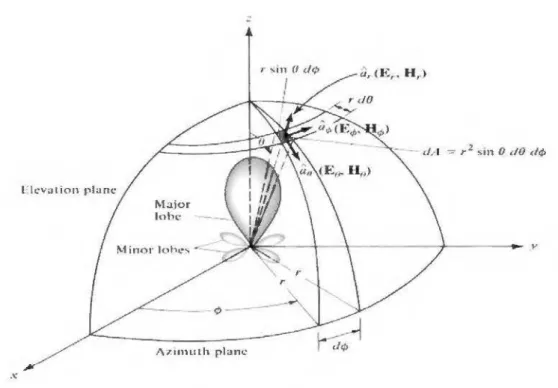
2.1.2.3. RadiationPattem
An antelllla radiation pattern is defined in the IEEE Standard Definitions [23] as:
''A mathematical fonction or a graphical representation of the radiation properties of the antenna as a fonction ofspace coordinates. In most cases, the radiation pattern is detennined in the far-field region and is represented as a fonction of the directional coordinates. Radiation properties include power flux density, radiation intensity, field
strength, directivity, phase or polarisation. "
Primarily, when measuring the radiation pattern, the property of most interest is the energy radiated relative to the antennas position [25].
.\: :: r ~ in (1 d<;>
1
:i,. < J<:, .• H ,.) l J\ Z IIlHilh planeFigure 2.2 Coordinate system for antenna anal y sis.
(http: 1 /slideplayer. com/slide/856265 31)
The antenna nnder test is placed at the origin and is rotated through ~ = 0° - 360° and
e
= 0°- 180° while the power is rneasured in the far-field. As shown in Figure 2.2, the x-z plane is considered the elevation plane and is norrnally aligned with the electric field vector and is called the E-plane. The x-y plane is norrnally aligned with the rnagnetic field vector and is terrned the H-plane.2.1.2.3.1. Antenna Field Region
As an antenna radiates, there are changes to the electrornagnetic field structure as the radiation rnoves away from the antenna at a distanceR. These changes can
Far-field (Fraunhofer)
n::gion
Radiating near-field (Fresnel) region
Reactiw near-ficlcl rcgioD
f _j
1 1~
R 1=
0.62 ..J D-'lÀ R2=2&/ÀFigure 2.3. Field regions of an antenna
(http: 1 /totalecer. blogspot. com/2 0 16/02/radiating-field-regions-ofantenna.html) 2.1.2.3.2. Reactive near-field region
The reactive near-field region, sometimes called the antenna region, is considered to be the vohune of the field in the immediate vicinity of the antenna. For the majority of antennas this region exists at R
<
0.62J
D3/À from the antenna, where Ris radius and D
is the maximmn antenna dimension. Confined within this region is a lùgh amount of non-propagating energy, or reactive power.2.1.2.3.3. Radiating near-field or Fresnel region
The radiating near-field, or Fresnel region does not display spherical power flow and varies as a fnnction of distance,
R,
from the antenna. Also, the longitudinal component of the electric field may be significant, for exarnple, ifusing the dipole fromfigure 2.3. The bonndaries for this region are between where R ~ 0.62J D3 (À and R<
2D2 /A,, and whereDis the largest dimension. If the antenna is very small compared to wavelength this region may not exist.
2.1.2.3.4. Radiating far-field or Fraunhofer region
In the radiating far-field or Fraunhofer region the field components are transverse to the radial direction from the antenna and all the power flow is directed outwards in a radial faslùon. In this region the shape of the field pattern is independent of the distance, R, from the antenna. The inner bonndary is taken to be the distance R
=
202 /')..., where D is the2.1.2.3.5. Characteristic impedance of EM waves
To help differentiate between near-field and far-field regions it is useful to analyse the characteristic impedance of plane waves. The characteristic impedance of a plane wave for a lossless medium is given by:
where:
z
=
r:u(Q)0
{i
fJ
=
f.lof.l, (2.11)êiJ
=
Permittivity offree space=
8.854 x 10⁻¹² (F/m)er = Relative permittivity of the dielectric mate rial
J..lD = Permeability of free space = 4n x 10-7 (H/m)
J.Lr=
Relative permeability ofthe magnetic materialFor plane waves, this impedance is also known as the intrinsic impedance of the medium. In free space, where
ZO
= 377n,
the E-field and H-field are orthogonal to each other and orthogonal to the direction of propagation. If the wave is in the near-field, in a free space environment,ZO
=F 377n
sin ce the fields are not orthogonal to each other, or in the direction of propagation.2.1.2.4. Velocity of Propagation
Another useful differentiation between the far-field and near-field regions, which gives an insight into the property of electromagnetic waves, is the velocity of propagation (mis). The velocity of propagation of a plane wave, sometimes known as phase velocity, is the speed at which a wave moves through a medinm and is given, for a lossless medinm, by:
1 (ù 1 (2.12)
vP =--;===- (ms ·)
...;'êJJ
k
where:
co= frequency (radis)
P
=.Jj.u:=
wavennmber (m-1)For a plane wave travelling in free space, the velocity is eqnal to the speed oflight, c = 2.998 x 10⁸ rn/s. As with the wave impedance, for the wave to be planar (i.e. in the
2.1.2.5. Directivity
Antenna directivity in the IEEE Standard Definitions of Terms for Antennas [26] as: "The ratio of the radiation intensity in a given direction from the antenna to the radiation intensity averaged over ali directions. The average radiation intensity is equal to the total power radiated by the antenna divided by 4n. If the direction is not specified.
the direction of the maximum radiation intensity is implied. ··
Essentially, this means that the directivity of an antenna is the ratio of the radiation intensity in a given direction over that of an isotropie source. This can be written as:
D =
..!!...
= 4n:U (2.13)Ua Prad
where,
U ~radiation intensity (W /unit solid angle)
U0 ~radiation intensity of an isotropie source (W /unit solid angle)
Prad ~ total radiated power (W)
If the antenna was to radiate in ali directions (isotropie radiator) then its directivity would be unity. As an isotropie radiator cannot be realized practically, the most comparable antenna has directivity different from any other antenna that have a higher directivity which means their patterns are more focused in a particular direction.
2.1.2.6. Antenna Efficiency (rl)
Like other microwave components, antennas can suffer from !osses. The total antenna efficiency takes into account the !osses at the input terminais, and within the structure of the antenna itself. The mismatch or reflection efficiency (TJr) is direct! y related to the return Joss (f) and can be defined as:
T]r = (1-l f 21. (2.14)
The radiation efficiency (TJ) is a measure of how much power is !ost in the antenna due to conductor and dielectric !osses. These !osses reduce the radiation in any given direction and can be expressed as:
Prad
2.1.2. 7. Gain
Antenna gain, G, is the product of efficiency and directivity, and is defined in the IEEE Standard Definitions ofTerms for Antennas [27] as:
"The ratio of the intensity, in a given direction, to the radiation intensity that would be
obtained
if
the power accepted by the antenna were radiated isotropically. The radiationintensity corresponding to the isotropically radiated power is equal to the power accepted by the antenna divided by 4n".
This can be expressed as:
G = 4TIU(</>,B)
Pin (2.16)
Unless specified, it is assumed that the antenna is receiving a signal in the direction of maximum gain. It is also common for the gain to be expressed in decibels and referenced to an isotropie source (G ~ 1 ), as shown in Equation 2.15.
G (dEi)~ JO Log (G/1). (2.17)
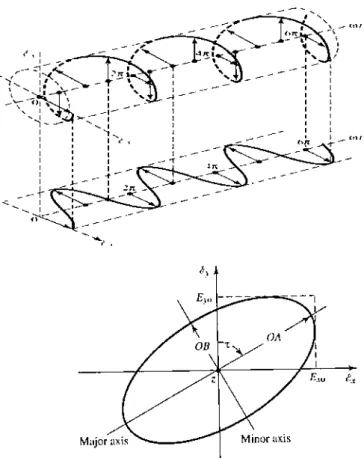
2.1.2.8. Polarization
The polarization of an antenna is the orientation of the electric field vector of the radiated wave and is defined in the IEEE Standard Definitions of Terms [28] as:
"The property of an electromagnetic wave describing the time-varying direction and relative magnitude of the electric-field vector; specifically, the figure traced as a function oftime by the extremity of the vector at afixed location in space, and the sense
in which it is traced, as observed along the direction of propagation"
Polarization is the curve traced by the tip of the electric field vector viewed in the direction of propagation. Figure 2.4 shows a typical trace as a function oftime [29].
The polarization of the wave may be linear, circular, or elliptical. The instantaneous electric field of a plane wave, travelling in the negative z direction, may be written as:
Ew - - - - - - - - 1
OA
E_w {:_,
Major axis----~
Figure 2.4. Rotation of a plane electromagnetic wave and its polarization ellipse at z = 0
as afimction oftime
(http: // sli deplayer. corn/ sli de/8 56 265 3/)
The instantaneous cornponents are related to their cornplex cmmterparts by: Ex (z, t) ~ Ey cos (rot+ Pz+ 8x)
Ey (z, t) ~Ex cos (rot+ Pz+ 8y).
(2.19) (2.20)
Where Ex andE y are the maximum magnitudes and 8x and 8y are the phase angles of the x and y cornponents, co is the anglliar frequency
2.1.2.9. Half- Power Beam-width
The HPBW can be defined as half the maximum value that is calculated between two angles from the main lobe [30]. In other words, the HPBW is rneasured at the main beam, by calclliating the angle of the gain which bas the value of the maximum value minus 3 dB as shown in Figure 2.4. The beam width is an important parameter for the antelllla and is usually referred to when users use it.
The beam width is always used as a trade-offbetween the side lobe levels to analyze the antelllla performance and pis the propagation constant.
![Figure 1.1 Wireless Sensor Network. [3]](https://thumb-eu.123doks.com/thumbv2/123doknet/7650319.237387/21.897.225.686.100.361/figure-wireless-sensor-network.webp)

![Figure 3.4 Surface wave dispersion pattem of metal strips. [78]](https://thumb-eu.123doks.com/thumbv2/123doknet/7650319.237387/62.892.228.735.95.427/figure-surface-wave-dispersion-pattem-metal-strips.webp)
![Figure 3.5: Two-dimensional crystalline structure. [78]](https://thumb-eu.123doks.com/thumbv2/123doknet/7650319.237387/64.892.214.662.116.530/figure-dimensional-crystalline-structure.webp)
![Figure 3.9: EBG antenna ofTemelkuran. [78]](https://thumb-eu.123doks.com/thumbv2/123doknet/7650319.237387/67.892.139.730.560.778/figure-ebg-antenna-oftemelkuran.webp)
![Figure 3.11: EBG LensAntenna [78]](https://thumb-eu.123doks.com/thumbv2/123doknet/7650319.237387/68.892.232.680.504.793/figure-ebg-lensantenna.webp)
![Figure 4. 2. Geometry of the proposed active reconfigurable cylindrical FSS antenna [45]](https://thumb-eu.123doks.com/thumbv2/123doknet/7650319.237387/78.892.242.770.283.564/figure-geometry-proposed-active-reconfigurable-cylindrical-fss-antenna.webp)
