HAL Id: hal-01326930
https://hal.inria.fr/hal-01326930
Submitted on 6 Jun 2016
HAL is a multi-disciplinary open access
archive for the deposit and dissemination of sci-entific research documents, whether they are pub-lished or not. The documents may come from teaching and research institutions in France or
L’archive ouverte pluridisciplinaire HAL, est destinée au dépôt et à la diffusion de documents scientifiques de niveau recherche, publiés ou non, émanant des établissements d’enseignement et de recherche français ou étrangers, des laboratoires
Rule-driven service coordination middleware for
scientific applications
Héctor Fernández, Cédric Tedeschi, Thierry Priol
To cite this version:
Héctor Fernández, Cédric Tedeschi, Thierry Priol. Rule-driven service coordination middle-ware for scientific applications. Future Generation Computer Systems, Elsevier, 2014, 35, �10.1016/j.future.2013.12.023�. �hal-01326930�
Rule-Driven Service Coordination Middleware
for Scientific Applications
H´ector Fern´andez1, C´edric Tedeschic, Thierry Priolb
aIRISA. University of Rennes 1 / INRIA bINRIA
cVrije University Amsterdam
Abstract
With the proliferation of Web services, scientific applications are more and more designed as temporal compositions of services, commonly referred to as workflows. To address this paradigm shift, different workflow management systems have been proposed. While their efficiency has been established over centralized static systems, it is questionable over decentralized failure-prone platforms.
Scientific applications recently started to be deployed over large dis-tributed computing platforms, leading to new issues, like elasticity, i.e., the possibility to dynamically refine, at runtime, the amount of resources dedi-cated to an application. This raised again the demand for new programming models, able to express autonomic self-coordination of services in a dynamic platform.
Nature-inspired, rule-based computing models recently gained a lot of at-tention in this context. They are able to naturally expressing parallelism, distribution, and autonomic adaptation. While their high expressiveness and adequacy for this context has been established, such models severely suffer from a lack of proof of concepts. In this paper, we concretely show how to leverage such models in this context. We focus on the design, the imple-mentation and the experimental validation of a chemistry-inspired scientific workflow management system.
Keywords: Service coordination; Workflow execution; Nature-inspired computing; Rule-based programming; Decentralization
1. Introduction
Until recently, scientific applications were commonly hard-to-maintain unreadable scripts, leading to a poor reusability level and high maintenance costs. With the proliferation of Web services and the increasing adoption of service-oriented computing, whose primary goal is to make a collection of software services accessible through the network, scientists started to develop their applications as compositions of Web services, today commonly referred to as workflows. This shift of paradigm recently led to more reutilization, and experiment sharing in the community. The specification and execution of such workflows are managed by workflow management systems, responsi-ble for the coordination of involved services. Addressing the limitations of initial workflow languages such as the BPEL business standard [1], differ-ent systems, for example Taverna [2], Kepler [3], Triana [4], Pegasus [5], or Askalon [6] provide nice features such as implicit parallelism and data-driven coordination, increasing the level of abstraction regarding execution manage-ment as well as improving the manageability of science workflows, as it was formulated by Zhao, Raicu and Foster in 2008 [7].
Science workflows need to be deployed over more and more distributed environments, to face the computing power they require. Let us for instance cite the Magellan project, which aims at providing a large and elastic dis-tributed infrastructure for science [8]. Such platforms are the new target for scientists needing to run their applications. They appear as one major solution to face their computing requirements. Thus it appears that future scientific workflow systems and languages should provide a natural way to express both workflows and platform characteristics. We identify several crit-ical features the future WMS must address: (i) the high degree of parallelism and distribution of services deployed, (ii) the potential issues brought by a centralized coordinator such as single points of failure and scalability, and (iii) the dynamicity and distribution of the next generation of distributed infrastructures. These features call for new specification tools, able to easily express them.
Lately, nature metaphors, and in particular chemistry-inspired analogies have been identified as a promising source of inspiration for developing new approaches for autonomous service coordination [9]. Among them, the chem-ical programming paradigm is a rule-based programming model built atop a high level execution model within which a computation is basically seen as a set of reactions consuming some molecules of data interacting freely
within a chemical solution producing new ones (resulting data). Reactions take place in an implicitly parallel, autonomous, and decentralized manner. More recently, the Higher-Order Chemical Language (HOCL) [10] raised the chemical model to the higher-order, providing a highly-expressive paradigm : every entity in the system (in our case data, services and their dependencies, and the platform itself) is seen as a molecule. Moreover, rules can apply on other reaction rules, programs dynamically modifying programs, opening doors to dynamic adaptation. This model is now envisioned as an alterna-tive to naturally express autonomous coordination [11]. However, while its expressiveness and adequacy to service coordination have been established, the actual experimentation of the chemical model has remained quite limited until now. There is a strong need of a proof of concept to show its viability, in particular compared to current WMSs.
Contribution. In this paper, we present a workflow managment system able to solve a wide variety of workflow patterns both in a centralized and a decentralized way following the chemical model. Its implementation and performance evaluation on different classic scientific workflows presenting different characteristics are discussed. For the sake of comparison and dis-cussion, workflows tested were also executed on top of Taverna and Kepler WMS, validating our software prototype, and establishing the viability of the concept.
Outline. Section 2 introduces the preliminaries of our work, namely workflow management systems and the Higher-Order Chemical Language (HOCL). Section 3 describes the architecture and workflow engine we have built. We show how a workflow is described in our model, and how chemical rules are defined and combined so that they can solve a wide variety of workflow patterns. Section 4 focus on the implementations of both centralized and de-centralized versions of the system defined. Section 5 details the experimental campaign and its results. Section 6 discusses related works. Section 7 draws a conclusion.
2. Background
In this section, we introduce the two background areas of this work : workflow management systems and the chemical computing model.
2.1. Workflow Management for e-Science
The increase in the reliance on service-oriented architectures (SOA) in e-sciences resulted in applications to be more and more defined as work-flows of services. As a natural consequence, workflow management systems have gained recently considerable attention. The BPEL standard [1] and its followers [12] were at first briefly adopted by the scientific community. Then, science-oriented workflow languages and systems were designed, to cope with the different characteristics of scientific applications, such as a high parallelism degree and the need for scheduling. In this way, a number of systems were designed for the expression and execution of scientific work-flows. Taverna [2], Kepler [3], Triana [4], Pegasus [5] or Askalon [6] provide nice features such as implicit parallelism and data-driven coordination, in-creasing the abstraction regarding execution management while improving the efficiency and manageability. All typically provide a visual notation for service composition.
The remainder of this section reviews the two open-source workflow sys-tems used for the sake of validation of our work : Taverna and Kepler. We chose Kepler and Taverna because they are among the most used and mature open-source scientific WMS. As mature as it can be, we chose not to use Pe-gasus as the resource management is integrated into the workflow manager, which is not our primary concern here.
Taverna [2] builds upon service-oriented architectures, and the web service standards. Interactions between services (referred to as processors) are de-fined using the XML-based Scufl language or a GUI. Taverna is data-driven. Data-dependencies specify links among different services, so parallelism is implicit, and optimized at run time. Note that control-dependencies can also be specified by links that define precedence conditions among proces-sors. Taverna’s workflow engine is centralized ; a unique coordinator manages the coordination of all computation blocks.
Kepler is a centralized workflow engine built upon Ptolemy II [13], ini-tiated in part by the members of the Science Environment for Ecological Knowledge (SEEK)1. It also relies on a data-driven model for simulating and designing real-time and concurrent workflows using a proprietary modeling markup language called MoML. This language is based on the actor-oriented modeling paradigm which consists in a composition of computation blocks
called actors representing operations or data sources. Thanks to its data-driven behavior, Kepler provides an intuitive and implicit parallel execution. However, it may hinder the execution of more complex workflow patterns. In recent versions, some control structures can be supported through more sophisticated programming.
The limitation of both Taverna and Kepler is the lack of (i) facilities to describe more complex control-flow patterns, and (ii) support for a decen-tralized coordination of the workflow execution.
2.2. Rule-Based Chemical Programming
Nature analogies, and more specifically bio-chemical metaphors, have re-cently gained momentum in the construction of programming models coping with the requirements of the Internet of Services [9]. Initially proposed to nat-urally express highly parallel programs, the chemical programming paradigm exhibits properties required in emerging service platforms and naturally ex-presses autonomic coordination.
According to the chemical metaphor, molecules (data) float in a chemi-cal solution, and react according to reaction rules (program) producing new molecules (resulting data). These reactions take place in an implicitly par-allel, autonomous, and non-deterministic way until no more reactions are possible, a state referred to as inertia. The computation is carried out ac-cording to local conditions without any central coordination, ordering or serialization. This programming style allows writing programs cleared of any artificial sequentiality, so the programmer can concentrate on the functional aspects of the problem solved. The execution model is reactive, in the sense that the presence of a molecule suffices to trigger a reaction requiring such a molecule. Nevertheless, as it will be shown, it can express sequentiality if needed.
Such a model takes its roots in concurrent multiset rewriting and was formalized in [14], and then put in practice through the Higher-Order Chem-ical Language (HOCL) [10]. In HOCL, every entity is a molecule, including reaction rules. A program is a solution of molecules, formally a multiset of atoms, denoted A1, A2, . . . ,An, “,” being the associative and commutative operator of construction of compound molecules. Atoms can be constants (integers, booleans, etc.), reaction rules, tuples of n atoms, denoted A1:A2: . . . :An, or sub-solutions, denoted hMii, where Mi is the molecule content of the sub-solution. A reaction involves a reaction rule replace P by M if V and a molecule N satisfying the pattern P and the reaction condition V .
The reaction consumes the molecule N to produce a new molecule M. This rule can react as long as a molecule satisfying the pattern P exists in the solution. Its one-shot variant, denoted one P by M if V , reacts only once, and is consumed in the reaction. Rules can either appear explicitly or be directly named using the let operator, allowing to use only this name in the solution. Let us consider the simple HOCL program below that extracts the maximum even number from a set of integers.
1.01 let selectEvens = replace x, ω by ω if x%2 ! = 0 in 1.02 let getM ax = replace x, y by x if x ≥ y
1.03 in 1.04 h
1.05 hselectEvens, 2, 3, 5, 6, 8, 9i,
1.06 replace-one hselectEvens = s, ωi by getM ax, ω 1.07 i
The selectEvens rule removes odd numbers from the solution, by re-peated reactions with an integer x, ω denoting the whole solution in which selectEvens floats, deprived of x. The getM ax rule reacts with two integers x and y such that x ≥ y and replaces them by x. In a solution of integers, this rule, by its repeated application, extracts the maximum value. The solution is composed by (i) a sub-solution containing the input integers along with the selectEvens rule, and (ii) a higher-order rule (on Line 1.06) that will open the sub-solution, extract the remaining (even) numbers and introduce the getM ax rule.
Solving the problem requires the sequentiality of the reactions of the two rules. This can be achieved by the higher order : in an HOCL program, a sub-solution can react with other elements as soon as it has reached the state of inertia. In other terms, the higher-order rule will react with the sub-solutions only when no more reactions are possible within it, i.e., when it contains only even numbers. (Note that the order in which odd numbers are deleted is non-deterministic.) The result is then as follows :
h
hselectEvens, 2, 6, 8i,
replace-one hselectEvens = s, ωi by getM ax, ω i
Then, the higher-order rule reacts with it, extracting remaining numbers, introducing dynamically the getM ax rule, and in this way triggering the second phase of the program where the maximum value is kept. The solution is then :
h2, 6, 8, getM axi
getM ax then reacts with pairs of integers until only 8 remains. Note that, due to the higher order, putting both rules directly in the solution of integers could entail a wrong behavior as the pipeline between the two rules would be broken, possibly leading to a wrong result. For instance, if getM ax reacts first with molecules 8 and 9, 8 would be deleted.
While this example is quite simple, it already provides the intuition be-hind autonomic coordination and adaptation, and its simple programming style. These features are explored in more detail in [15, 16, 17]. Furthermore, as a rule-based language, HOCL provides a high level of abstraction for the modelling of the service interactions, as rules allow to define the collabora-tions without having to interact with the individual services.
3. Chemistry-Inspired Workflow Management
In this section, we describe an HOCL-based workflow management sys-tem. First, the coordination mechanisms developed, which build upon higher-order chemistry, are presented. Then, the architecture underlying it, for both centralized or decentralized coordination are described. The con-cepts presented in this section take their origin in the founding work presented in [18].
3.1. Workflow Representation
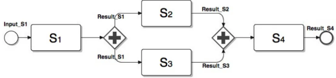
Let us consider a simple workflow expressed using BPMN (Business Pro-cess Modeling Notation) [19], and composed of the four services S1, S2, S3 and S4, as illustrated in Figure 1. In this example, after S1completes, S2 and S3 can be invoked in parallel. Once S2 and S3 have both completed, S4 can be invoked. Using any of the existing BPMN editors [20], we assume data and control dependencies are translated to a traditional workflow definition language, such as the well-known BPEL [1] or SCUFL [21]. For instance, a BPEL specification could be translated into a chemical program, as is de-tailed in [22]. Even though HOCL is used to describe and execute workflow
specifications, our purpose is to show its potential as executable workflow language. Thus, the general shape of the chemical representation of a work-flow is as follows : the main solution is composed of as many sub-solutions as there are WSes in the workflow. Each sub-solution represents a WS with its own data and control dependencies with other WSes. More formally, a WS is a molecule of the form W Si : h. . .i where WSi refers to the symbolic name given to the service whose connection details and physical location are hidden.
Figure 1: Simple workflow example.
Based on the workflow shown in Figure 1, an example of its chemical representation is illustrated by Figure 2. In this example, W S1 : h. . .i to W S4 : h. . .i represent WSes in the solution. The relations between WSes are expressed through molecules of the form Dest:WSi with W Si being the destination WS where some information needs to be transferred. For instance, we can see in the W S1 sub-solution that WS1 will transfer some information (its outcome) to WS2 and WS3 (Line 2.02).
2.01 h // Workflow’s solution
2.02 WS1:hCall:S1, Param:hin1i, Dest:WS2, Dest:WS3i, // WS1 sub-solution
2.03 WS2:hDest:WS4, replace Result:WS1:value1 by Call:S2, Param:hvalue1ii,
2.04 WS3:hDest:WS4, replace Result:WS1:value1 by Call:S3, Param:hvalue1ii,
2.05 WS4:hreplace Result:WS2:value2, Result:WS3:value3 by Call:S4, Param:hvalue2ii
2.06 i
Figure 2: Chemical workflow representation.
Let us have a more precise look on these dependencies. WS2 contains a data dependency: it requires a molecule Result:WS1:value1 containing
the result of S1 to be invoked (second part of Line 2.03). The two molecules produced by the reaction represent the call to S2 and their input parameters. They are expressed using a molecule of the form Call:Si, and a molecule Param:hin1, ..., inni, where in1, ..., inn represent the input parameters to call service Si. In Figure 2, this input parameter corresponds to the result of some previous service Sj. WS3 works similarly. WS4 performs a control pattern known as synchronization. It needs to wait until both WS2 and WS3 have completed, in other words, until the molecules Result:WS2:value2 and Result:WS3:value3 appear in its own sub-solution, to start its execution. In addition, a data dependency is also expressed in WS4 : the result of S2 is required to call S4.
To ensure the execution of a chemical workflow, additional generic chem-ical rules (i.e., independent of any specific workflow) must be defined. These rules consume and generate additional molecules to manage transfer of in-formation between services, condition checking, fault detection, and more complex control flows. To express the whole logic of a workflow, these rules are composed relying on the analogy of molecular composition. This consists in the composition of several molecules, which are combined based on data molecule dependencies, and whose reactions produce new molecules reacting in their turn, and so on, until the workflow is completed.
3.2. Generic Rules for Invocation and Transfer
Common tasks in a workflow of services are service invocation and in-formation transfer between services. We now review three generic rules il-lustrated in Algorithm 1, responsible for these basic tasks, and that will be commonly encountered in the compositions presented later. The invokeServ rule encapsulates the actual invocation of services. Upon reaction, it invokes the Web Service Si, by consuming the tuple Call:Si representing the invoca-tion itself, and Param:hin1, ..., inni representing the input parameters, and generates the molecules containing the results of the invocation in the WSi sub-solution. The molecule Flag Invoke is a flag whose presence in the solution indicates that the invocation can take place. The preparePass rule is used for preparing the messages aimed at transferring the results to their destination services, that will in turn trigger the execution of the passInfo rule.
Rule passInfo transfers molecules of information between WSes. This rule reacts with a molecule WSi:hPass:d:hω1 ii that indicates that some molecules (here denoted ω1) from WSi needs to be transferred to d. These
Algorithm 1 Basic generic rules.
3.01 let invokeServ = replace WSi:hCall:Si, Param:hin1, . . . , inni, Flag Invoke, ω i, 3.02 by WSi:hResult:WSi:hvaluei, ω i
3.03 let preparePass = replace WSi:hResult:WSi:hvaluei, Dest:WSj, ωi
3.04 by WSi:hPass:WSj:hCompleted:WSi:hvaluei i i
3.05 let passInfo = replace WSi:hPass:WSj:h ω1 i, ω2 i, WSj:h ω3i 3.06 by WSi:h ω2 i, WSj:h ω1, ω3i
molecules, once inside the sub-solution of d will trigger the next step of the execution. Therefore, the molecule ω1 will be transferred from sub-solution WSi to sub-solution d, when reacting with the passInfo rule.
3.3. Complex Workflow Patterns
With the generic rules described until now, the engine can only support data flows which induce a deterministic behavior to the execution of our pro-grams. However, more complex control flows should be taken into account, in order to solve a broader range of workflow definitions. We now illustrate how HOCL can be leveraged to deal with complex control flows, by detailing a particular pattern known as Simple Merge.
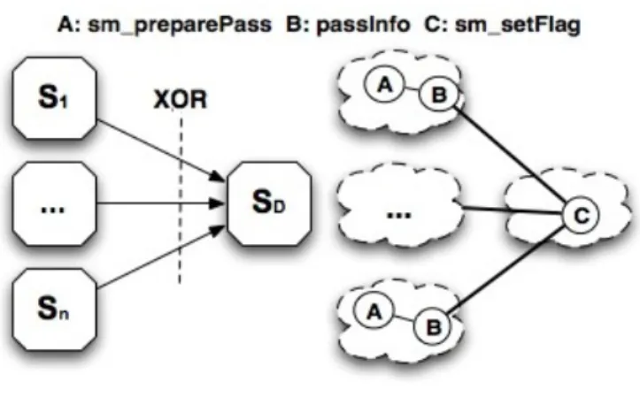
As illustrated in Figure 3, a simple merge pattern resembles a XOR oper-ation. It involves a structure where two or more source service flows (denoted S1 to Sn on Figure 3 converge into a single destination (denoted SD) asyn-chronously. The destination service must however be launched only once, regardless of the number of incoming branches. In other words, only the first source service to complete will influence the remainder of the workflow execution.
Figure 3: Simple merge pattern.
To enhance our workflow engine with the support of the simple merge pattern, we need to define the appropriate generic rules and dispatch them in the sub-solutions of WSs involved. These rules are given in Algorithm 2. The sm preparePass reaction rule is used to add, in the sub-solution of ev-ery incoming service, a particular Merge molecule to the information to be transferred to the destination service (see Lines 4.01 and 4.03). The destina-tion WS waits for this molecule and only the first Merge molecule received in its sub-solution will be consumed. Next, sm setFlag reaction rule takes place, producing one molecule of the form Flag Invoke, that allows to trigger the service invocation. The following Merge molecules received will be ignored. In terms of molecular composition, each source WS will have in its sub-solution one sm preparePass rule (A on Figure 3) and one passInfo rule (denoted B on Figure 3), they are composed with sm setFlag rule (C ) in the destination WS.
Algorithm 2 Generic rules - Simple merge pattern
4.01 let sm preparePass = replace Dest:WSj, Result:WSi:hvaluei
4.02 by Pass:WSj:hResult:WSi:hvaluei, Mergei
4.03 let sm setFlag = replace-one Merge by Flag Invoke
Note that we omit more complex control flows, such as synchronization merge, exclusive choice or discriminator, as it is not the scope here. The
description of the support for a wide range of control flow patterns, as well as its design process, can be found in the research report [23].
On the other hand, even though the design of large workflows could lead to the creation of a large number of rules, which is a problem inherent to rule-based languages, one point is that, the HOCL engines themselves include the generic rules needed to execute the specific workflows described. More precisely, it means that the workflow itself, as defined by the programmer, is quite reduced, as, as discussed before, only the name of the rules to be used, and not the rule itself needs to be included by the programmer. In our work, we consider that handling errors is delegated to the HOCL compiler and runtime, which is in charge to validate the definition and to execute the rules.
To sum up, the coordination is achieved through a set of autonomic and local reactions taking place within each WS’s sub-solution (or between two WSs’ sub-solutions), providing adequate abstractions for a natural expres-sion of a decentralized coordination for virtually all identified workflow pat-terns [24].
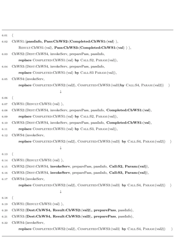
3.4. Execution Example
To better understand how the coordination between chemical engines works, we here present the execution of the workflow example illustrated in Figure 2, for which we focus on each step of the coordination logic. These steps are listed in Figures 4 (steps 1-3), 5 (steps 4-7) and 6 (steps 8-10). Recall that, thanks to the higher-order property, reaction rules react themselves with other molecules. As we have discussed already, the example is composed by four ChWSes applying parallel split and synchronization patterns. More precisely, the execution is as follows: After ChWS1 completes, it forwards the result to ChWS2 and ChWS3 in parallel. Once ChWS2 and ChWS3 have completed, ChWS4 can start. Consider that each chemical local engine is responsible for the reactions taking place within its sub-solution in the multiset, thus respecting at runtime the decentralization designed. Indeed, for the sake of clarity, we only mention the molecules that take part in the logic of the coordination.
The first step (Lines 5.02-5.05) corresponds to the initial state of the multiset, illustrated in Figure 4. Initially, the only possible reaction is inside ChWS1, the invokeServ rule is triggered by the HOCL interpreter of ChWS1, producing the outcome molecule Result:ChWS1:hvali. This molecule rep-resents the result of the invocation of S1. Then, the preparePass rule
con-sumes the molecules Dest:destination and Result:ChWS1:hvali, preparing the parallel split. Therefore, it produces two new molecules for the dis-tribution of this result to ChWS2 and ChWS3 (Line 6.02). Finally, still through ChWS1, passInfo triggers it by transferring in parallel the outcome of ChWS1.
Once the information is received by ChWS2 and ChWS3, the re-actions (Lines 6.09 and 6.11) are triggered, in parallel, producing the needed molecules to invoke S2 and S3. Thus, molecules of the form Call:Si and Param:(val) contained into ChWS2 and ChWS3 respectively, launch the invokeServ rule (Lines 6.08-6.10) that generates the result of S2 and S3. Similarly to ChWS1, the molecules Result:ChWS2:hval2i and Result:ChWS3:hval3i react with the preparePass rule. Finally, in ChWS2 and ChWS3, the passInfo rule propagates the molecule Pass:ChWS4:h in-formation i to ChWS4 (Lines 7.03-7.04).
The execution ends with the last steps of Figure 6, processed by ChWS4’s local engine. Once the information from ChWS2 and ChWS3 is received by ChWS4, the reaction rule (Line 7.12) can react with results molecules to pro-duce two new molecules for invoking service S4 (Line 7.18). Finally, invoke-Serv rule will take place producing the final result Result:ChWS4:hval4i.
To sum up, local engines of each ChWSes are co-responsible for applying workflow patterns, invoking services, and propagating the information to other ChWSes. The coordination is achieved as reactions become possible, in an asynchronous and decentralized manner.
4. Architectures and Implementations
To put into practice and validate the concepts presented before, we have developed an architectural framework (whose main ideas are taken from our initial work in [18]) and three software prototypes exhibiting different levels of decentralization regarding processing and communications. Firstly, we devel-oped a shared space-based architecture referred to us as HOCL-TS, inspired by [18]. Secondly, and also for the sake of comparison and discussion, two other architectures were developed, namely HOCL-C and HOCL-P2P, fully centralized, and fully distributed, respectively. These three architectures rely in common on an HOCL-based workflow engine, enhanced with the molecu-lar composition-based rules for the modelling of service interactions. Let us briefly introduce these architectures. Figure 7 illustrates their relationships.
5.01 h
5.02 ChWS1:hDest:ChWS2,Dest:ChWS3, invokeServ, preparePass, passInfo, Call:S1, Param:in1i,
5.03 ChWS2:hDest:ChWS4, invokeServ, preparePass, passInfo, replace Completed:ChWS1:hvali by Call:S2, Param:(val)i,
5.04 ChWS3:hDest:ChWS4, invokeServ, preparePass, passInfo, replace Completed:ChWS1:hvali by Call:S3 Param:(val)i,
5.05 ChWS4:hinvokeServ,
replace Completed:ChWS2:hval2i, Completed:ChWS3:hval3i by Call:S4, Param:(val2)i
5.06 i
↓
5.07 h
5.08 ChWS1:hDest:ChWS2,Dest:ChWS3, preparePass, passInfo, invokeServ, Call:S1, Param:in1 i,
5.09 ChWS2:hDest:ChWS4, invokeServ, preparePass, passInfo, replace Completed:ChWS1:hvali by Call:S2, Param:(val)i,
5.10 ChWS3:hDest:ChWS4, invokeServ, preparePass, passInfo, replace Completed:ChWS1:hvali by Call:S3 Param:(val)i,
5.11 ChWS4:hinvokeServ,
replace Completed:ChWS2:hval2i, Completed:ChWS3:hval3i by Call:S4, Param:(val2)i
5.12 i
↓
5.13 h
5.14 ChWS1:hDest:ChWS2,Dest:ChWS3, preparePass, passInfo, Result:ChWS1:hvalii,
5.15 ChWS2:hDest:ChWS4, invokeServ, preparePass, passInfo, replace Completed:ChWS1:hvali by Call:S2, Param:(val)i,
5.16 ChWS3:hDest:ChWS4, invokeServ, preparePass, passInfo, replace Completed:ChWS1:hvali by Call:S3 Param:(val)i,
5.17 ChWS4:hinvokeServ,
replace Completed:ChWS2:hval2i, Completed:ChWS3:hval3i by Call:S4, Param:(val2)i
5.18 i
6.01 h
6.02 ChWS1:hpassInfo, Pass:ChWS2:hCompleted:ChWS1:hvali i, Result:ChWS1:hvali, Pass:ChWS3:hCompleted:ChWS1:hvali i i,
6.03 ChWS2:hDest:ChWS4, invokeServ, preparePass, passInfo, replace Completed:ChWS1:hvali by Call:S2, Param:(val)i,
6.04 ChWS3:hDest:ChWS4, invokeServ, preparePass, passInfo, replace Completed:ChWS1:hvali by Call:S3 Param:(val)i,
6.05 ChWS4:hinvokeServ,
replace Completed:ChWS2:hval2i, Completed:ChWS3:hval3iby Call:S4, Param:(val2)i i ↓
6.06 h
6.07 ChWS1:hResult:ChWS1:hvali i,
6.08 ChWS2:hDest:ChWS4, invokeServ, preparePass, passInfo, Completed:ChWS1:hvali,
6.09 replace Completed:ChWS1:hvali by Call:S2, Param:(val)i,
6.10 ChWS3:hDest:ChWS4, invokeServ, preparePass, passInfo, Completed:ChWS1:hvali,
6.11 replace Completed:ChWS1:hvali by Call:S3, Param:(val)i,
6.12 ChWS4:hinvokeServ,
replace Completed:ChWS2:hval2i, Completed:ChWS3:hval3i by Call:S4, Param:(val2)i i ↓
6.13 h
6.14 ChWS1:hResult:ChWS1:hvali i,
6.15 ChWS2:hDest:ChWS4, invokeServ, preparePass, passInfo, Call:S2, Param:(val)i,
6.16 ChWS3:hDest:ChWS4, invokeServ, preparePass, passInfo, Call:S3, Param:(val)i,
6.17 ChWS4:hinvokeServ,
replace Completed:ChWS2:hval2i, Completed:ChWS3:hval3i by Call:S4, Param:(val2)i i ↓
6.18 h
6.19 ChWS1:hResult:ChWS1:hvali i,
6.20 ChWS2:hDest:ChWS4, Result:ChWS2:hval2i, preparePass, passInfoi,
6.21 ChWS3:hDest:ChWS4, Result:ChWS3:hval3i, preparePass, passInfoi,
6.22 ChWS4:hinvokeServ,
replace Completed:ChWS2:hval2i, Completed:ChWS3:hval3i by Call:S4, Param:(val2)i i
7.01 h
7.02 ChWS1:hResult:ChWS1:hvali i,
7.03 ChWS2:hPass:ChWS4:hCompleted:ChWS2:hval2i i, passInfo, Result:ChWS2:hval2i i,
7.04 ChWS3:hPass:ChWS4:hCompleted:ChWS3:hval3i i, passInfo, Result:ChWS3:hval3i i,
7.05 ChWS4:hinvokeServ,
replace Completed:ChWS2:hval2i, Completed:ChWS3:hval3i by Call:S4, Param:(val2)i
7.06 i ↓ 7.07 h 7.08 ChWS1:hResult:ChWS1:hvali i, 7.09 ChWS2:hResult:ChWS2:hval2i i, 7.10 ChWS3:hResult:ChWS3:hval3i i,
7.11 ChWS4:hinvokeServ, Completed:ChWS2:hval2i, Completed:ChWS3:hval3i,
7.12 replace Completed:ChWS2:hval2i, Completed:ChWS3:hval3i by Call:S4, Param:(val2)i
7.13 i ↓ 7.14 h 7.15 ChWS1:hResult:ChWS1:hvali i, 7.16 ChWS2:hResult:ChWS2:hval2i i, 7.17 ChWS3:hResult:ChWS3:hval3i i,
7.18 ChWS4:hinvokeServ, Call:S4, Param:(val2)i
7.19 i ↓ 7.20 h 7.21 ChWS1:hResult:ChWS1:hvali i, 7.22 ChWS2:hResult:ChWS2:hval2i i, 7.23 ChWS3:hResult:ChWS3:hval3i i, 7.24 ChWS4:hResult:ChWS4:hval4i i 7.25 i
Their design and implementation will be detailed in Sections 4.1 and 4.2, respectively :
Figure 7: Three architectures.
• HOCL-C. Centralized, HOCL-C is an architecture composed of a sin-gle chemical engine playing a role similar to that of traditional workflow engines.
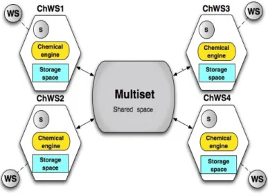
• HOCL-TS. Inspired by the architectural framework proposed in [18], HOCL-TS (for TupleSpace) is composed of a set of distributed chemi-cal engines coordinated through reading and (re)writing the multiset, which now acts as a shared space containing the information about the workflow to be executed. This architecture provide loosely-coupled in-teractions between services. The execution is now decentralized, while the multiset remains a central mean for services to communicate. • HOCL-P2P. Fully decentralized, HOCL-P2P is based on the direct,
point-to-point communication of chemical engines, when executing the workflow. The multiset is now distributed on the nodes involved prior to the execution. Note that HOCL-P2P shares some similarities with the work presented in [25].
4.1. Architectures
We now detail how an HOCL-based workflow engine can be powered over both centralized and decentralized architectures.
4.1.1. HOCL-C
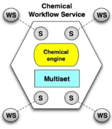
Following traditional workflow management systems, the coordination can be managed by a single node, referred to as the chemical workflow ser-vice, as illustrated by Figure 8. First, notice the S components, which act as interfaces with the actual remote Web services to be called. Then, the multiset contains the chemical workflow definition and its coordination in-formation (as presented before). It is accessed by the chemical engine to perform the required reactions.
Figure 8: HOCL-C architecture.
4.1.2. HOCL-TS
Distributing the workflow execution means that each service involved will participate in the coordination process. In HOCL-TS, each Web service is chemically encapsulated, to form what we refer to as a Chemical Web Ser-vice (ChWS). There is as many ChWSes as Web serSer-vice participating in a service composition. Each ChWS is equipped with a chemical engine and a local copy of a part of the multiset, which its chemical interpreter will act on. The complete multiset, containing the workflow definition and thus all required coordination information, will now act as a space shared by all ChWSes involved in the workflow. In other words, ChWSes will communi-cate by reading and writing it, as illustrated by Figure 9. This architecture follows a loosely coupled interaction model, as ChWSes only keep a physical connection with the shared space, not with the other ChWSes. Note that however, the communication remains based on a centralized data space, that may become a bottleneck.
Figure 9: HOCL-TS architecture.
4.1.3. HOCL-P2P
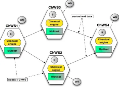
Suppressing this central space led to the design of HOCL-P2P, where both computations and communication are fully decentralized. In HOCL-P2P, a set of engines interact to execute a service composition in a peer-to-peer fash-ion, as proposed before for instance in works such as [25] or [26]. ChWSes now rely only on message passing to coordinate the workflow execution, as illustrated by Figure 10. This communication mechanism involves the partic-ipants in a more tightly coupled interaction, as they have to keep a physical reference to other ChWSes they are supposed to interact with. Each ChWS contains one portion of the workflow definition. These portions will be pro-cessed by the chemical engines of each ChWS. Consequently, this architecture assumes that the workflow portions are distributed prior to the execution.
Figure 10: HOCL-P2P architecture.
4.2. Software Prototypes
In this section, we discuss the actual implementation of three software prototypes, one for each of the previously described architectures. The low layer of our prototypes is an HOCL interpreter based on the on-the-fly com-pilation of HOCL specifications [27]. The prototypes are fully written in Java.
4.2.1. HOCL-C Prototype
The HOCL-C prototype is illustrated by Figure 11. As mentioned in Sec-tion 3.1, the workflow definiSec-tion is executed as a chemical program by the chemical workflow service. The low layer of the architecture is the HOCL interpreter. Given a workflow specification as input (an HOCL program), it executes the workflow by processing the multiset initially fed with the workflow definition, like any other HOCL program. The interface between the chemical engine and the distant services themselves is realized through the service caller component, which has been implemented with the DAIOS framework [28]. DAIOS provides an abstraction layer allowing dynamic con-nection to different flavors of services (SOAP or RESTFul), abstracting out the target service’s internals. Note that for our purpose, DAIOS was specif-ically extended to automatspecif-ically generate dynamic bindings, as well as the correct input and output messages required to realize the interface between
the chemical engines and a Web service. As such, web services can be easily changed by only specifying a web service description file (WSDL).
Figure 11: HOCL-C implementation.
4.2.2. HOCL-TS Prototype
The HOCL-TS prototype is illustrated on Figure 12. On a software point of view, the main difference between HOCL-TS and HOCL-C prototypes, be-yond the obvious architectural difference, stands in the multiset implementa-tion, as it now represents a shared space playing the role of a communication mechanism and a storage system.
The multiset is initially fed with the HOCL specification of the workflow. As we have detailed in Section 3.1, the workflow definition is comprised of one sub-solution per Web service involved. The information in one sub-solution can only be accessed by the corresponding ChWS. On each ChWS, a simple local storage space acts as a temporary container for the sub-solution to be processed by a local HOCL interpreter. The interface between a ChWS and a concrete Web service is still realized by the service caller based on the DAIOS framework, mentioned earlier.
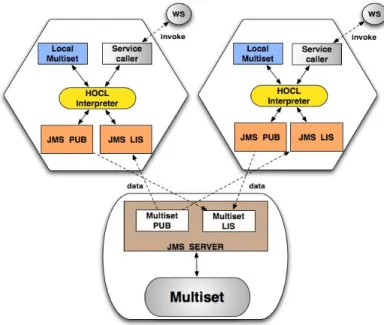
Figure 12: HOCL-TS implementation.
ChWSes communicate with the multiset using the Java Message Service (JMS) publisher/subscriber modules. Concretely, we use ActiveMQ (ver-sion 5.4.1), an implementation of the JMS 1.1 specification, which can be embedded in a Java application server. The multiset itself is encapsulated into a JMS server to allow concurrent reading and writing operations. The publish/subscribe messaging model is used by the ChWSes and the multiset whereby message producers called publishers pushing each message to each interested party called subscribers.
Initially, the multiset, through its JMS publisher (denoted PUB on Fig-ure 12) pushes the content of each WSi sub-solution to the JMS listener (denoted LIS on Figure 12) of the corresponding ChWS. Upon receipt, the content of the ChWSi solution is copied into the local multiset. When a ChWS has its HOCL interpreter that detected the inertia in its sub-solution, its publisher sends its content back to the multiset’s listener.
4.2.3. HOCL-P2P Prototype
The HOCL-P2P prototype, illustrated by Figure 13 can be seen as a static interconnection of HOCL-C prototypes, which are now Chemical Web Services (ChWSes) each one corresponding to a service involved in the work-flow. The workflow definition, which is comprised of one sub-solution per
Web service is now dispatched to each ChWS at build-time, informing each Web service statically about which other Web services to communicate.
Figure 13: HOCL-P2P implementation.
Thus, ChWSes still communicate among them through Java Message Service (JMS) publisher/subscriber, but without the need for the multiset to become a shared space. A JMS server is included into each ChWS. So when one node detects local inertia, its JMS publisher sends the outcome directly to the JMS listener of its successors in the workflow. DAIOS is again used to implement the service caller.
5. Experimentations
This section explores the viability and shows the benefits of using a chemistry-inspired system for service coordination. For the sake of validation, a series of experiments were conducted on our chemistry-inspired workflow system with the following objectives in mind : (i) capture the behavior of our approach when processing different types of workflows ; (ii) evaluate the benefits of a decentralized coordination compared to a centralized one when
modelling and executing different workflow structures ; (iii) establish the via-bility of a chemistry-based workflow management system in comparison with what appears to be the most mature workflow management systems (WM-Ses).
In the following, we present and analyse our experimental results. Five engines have been used : Taverna Workbench 2.2.0 [2], Kepler 2.0 [3], HOCL-C, HOCL-TS and HOCL-P2P. Note that we have considered Taverna and Kepler as representing validated standards we will see as references to achieve our objectives.
5.1. Workflow-based Applications
Three scientific workflows have been used. Illustrated by Figure 14 (left), BlastReport is a home-built bioinformatics workflow which retrieves a blast report of a protein in a database given its protein ID. The second one, Cardia-cAnalysis, illustrated on Figure 14 (right), is a cardiovascular image analysis workflow which extracts the heart’s anatomy from a series of image sequences by applying image processing algorithms, developed by the CREATIS-LRMN biomedical laboratory2. The third one, illustrated by Figure 15 is the well known Montage3, a classic astronomical image mosaic workflow processing large images of the sky.4
In order to transform these applications into chemical workflow defini-tions, we first analyzed their code, exposing their building functions or ex-ecutables as Web services, which will be part of the service composition. Finally, we composed those services based on their control and data depen-dencies to obtain the final outcome. For instance, the CardiacAnalysis appli-cation relies at a given point of his execution on an executable script, called Image Pyramid Decomposition. To construct the CardiacAnalysis workflow, this executable was installed as a Web service named pyramideDecom and composed with the other services, as more comprehensibly shown in Figure 14 (right). Please refer to [22] for more details.
These three workflows present different characteristics related to (i) the number of services involved, (ii) the amount of data exchanged and (iii) the
2http://www.creatis.insa-lyon.fr/site/ 3http://montage.ipac.caltech.edu/
4The workflow definitions used for each WMS are available
at https://www.irisa.fr/myriads/members/hfernand/hocl/workflows and http://www.myexperiment.org/workflows/2058.html.
complexity of the coordination required (data processing included, such as iterations of lists of objects). We attempt to characterize these workflows as follows :
• The BlastReport workflow includes 5 services, and presents a medium level of data exchange (simple objects, lists) and low coordination over-head – it is composed mostly of sequences.
• The CardiacAnalysis workflow includes 6 services, presenting a high amount of data exchange (complex objects, lists) and a high coordina-tion overhead (synchronizacoordina-tions, loop iteracoordina-tion, parallelism). This over-head does not appear on Figure 14 (right). It is due to the re-entrant nature of the services. For each workflow instances, multiple instances of tasks are created from the interpolation service to borderDetection and gradient services (lists of lists of elements to be processed). Some services produce lists of objects that need to be extracted one by one by iterators, and transferred to the next service asynchronously. • The Montage workflow includes 27 services, and exhibits a low amount
of data exchange (simple objects) and medium coordination overhead (parallelism and synchronization patterns).
In these workflows, each service invocation was deployed in a different ChWS to evaluate the decentralized coordination in the HOCL-TS and HOCL-P2P prototypes.
Figure 15: Montage workflow structure.
5.2. Centralized Experiments
The workflows were first run using Taverna, Kepler, and HOCL-C, on a local machine equipped with the Intel core-duo T9600 2.8 Ghz processor and 4GB of memory. Figures 16, 17 and 18 present the results. In Figure 16, a first encouraging result is that the execution time for the Montage workflow, (i.e., a workflow with limited data exchange and coordination overhead), on Kepler, Taverna and HOCL-C are quite similar, and even slightly reduced on the HOCL-C WMS.
Figure 16: Performance results, Montage.
For the BlastReport workflow on Figure 17, while results are again similar for the different WMSes, HOCL-C takes a little more time. This can be explained by the increased size of the multiset for the BlastReport workflow (in terms of number of molecules). However, in terms of ratio, execution times remain very close among the HOCL-* prototypes.
Figure 17: Performance results, BlastReport.
Finally, we can see in Figure 18 the increased coordination overhead of the CardiacAnalysis workflow. As mentioned before, this workflow relies on a lot of data processing related to the coordination itself, which, in the case
of HOCL-C, results in a significant increase of the size and processing time of the multiset. Also, no support for parallel execution has been implemented in the HOCL interpreter. These two optimization aspects will be investigated in the future.
Figure 18: Performance results, CardiacAnalysis.
5.3. Decentralized Experiments
The workflows were also executed with the HOCL-TS and HOCL-P2P prototypes. The experiments were conducted on the Grid’5000 platform [29], specifically, on the adonis and edel clusters, located in Grenoble, each node being equipped with two quad-core Intel Xeon E5520 processors, 24 GB of RAM and 40GB InfiniBand Ethernet cards. We now focus on the two right-most bars of Figures 16, 17 and 18.
A first observation is that the performance degradation using HOCL-TS and HOCL-P2P on the Montage workflow, as illustrated on Figure 16. Even though the coordination is executed locally on each ChWS (here the coordination is shared among 27 services in both designs), the time wasted with the network latency to coordinate the chemical nodes is higher than the workload using HOCL-C to coordinate the involved services. We can also notice that HOCL-TS performs slightly better than HOCL-P2P. This shows that some nodes in HOCL-P2P can lead to some bottlenecks, for instance when performing synchronization operations. In this case, in HOCL-P2P, when the number of incoming branches increases for a node, its workload can become important. In contrary, with HOCL-TS, such a load will be distributed between this node and the multiset.
On the BlastReport, a performance gain over HOCL-C is obtained with HOCL-TS and HOCL-P2P, thanks to the distribution of the coordination over the 5 services involved, as shown by Figure 17. The BlastReport work-flow starts to show the benefits by using decentralized prototypes, as an increment of the amount of data exchanged and coordination workload pro-vokes some degradations using centralized architectures. The decentralized prototypes present an acceptable performance in comparison with Kepler and Taverna, as depicted in Figure 17. For this workflow, TS and HOCL-P2P have similar performance. (There is no synchronization structures.)
For the CardiacAnalysis workflow, a considerable performance gain is again obtained using HOCL-TS and HOCL-P2P, demonstrating the benefits of a decentralized workflow execution when workflows present a high coordi-nation overhead like CardiacAnalysis, which is considered as a computation and data intensive workflow, as depicted in Figure 18. Exploiting the pro-cessing resources of each ChWS, the list handling and adaptation tasks are separately managed by each ChWS. Therefore, the time wasted with the network latency is now gained by reducing the workload of a central engine. Like for BlastReport, HOCL-TS and HOCL-P2P perform identically due to the absence of synchronization patterns in CardiacAnalysis.
5.4. Discussion
This series of experiments leads to several conclusions. They constitute a proof of the viability of a chemistry-based workflow engine, as for some representative workflows, its performance are similar and sometimes better to those of Kepler and Taverna. Kepler and Taverna are broadly considered as the defacto standards.
Nevertheless, the network latency comes up as a limitation for decen-tralized workflow engines when processing workflows such as Montage. Its reduced computational load and low rate of data exchange provoke that the coordination time in a decentralized architecture is higher than in a central-ized engine, due to the communications (network latency). Even thought the workflow execution time is affected by the network latency, the decentralized workflow systems are highly competitive when processing large workflows, as detailed in our previous work [30].
These experiments also show how HOCL-TS can perform slightly better than a fully decentralized architecture such as HOCL-P2P, even if HOCL-TS uses a central shared space as a communication mechanism. This should be further investigated. To deal with the decentralization of the multiset itself,
and build a fully decentralized solution with loosely-coupled interactions, some solutions based on peer-to-peer protocols, able to distribute and retrieve objects (here, workflow molecules) at large-scale [31] are being proposed. One of the next steps of this work is to build the HOCL-TS environment on top of such approaches to suppress the potentiality of a bottleneck, and thus propose a fully decentralized workflow engine.
6. Related Works
This section gives a more accurate comparison of our approach with some close recent works. We have observed two methods of distributed coordina-tion approach. In the first one, nodes interact directly. In the second one, they use a shared space for coordination.
Earlier works proposed decentralized architectures where nodes achieve the coordination of a workflow through the exchange of messages [32, 33]. Recently, some works [34, 25, 26] shown the increasing interest in this type of coordination mechanism. In [34], the authors introduce service invocation triggers, a lightweight infrastructure that routes messages directly from a producing service to a consuming one, where each service invocation trigger corresponds to the invocation of a service. In [25], an engine is proposed based on a peer-to-peer architecture wherein nodes (similar to local engines) are distributed across multiple computer systems. These nodes collaborate, in order to execute a workflow with every node executing a part of it. Lately, a continuation-passing style, where information on the remainder of the ex-ecution is carried in messages, has been proposed [26]. Nodes interpret such messages and thus conduct the execution of services without consulting a centralized engine. However, this coordination mechanism implies a tight coupling of services in terms of spatial and temporal composition. Nodes need to know explicitly which other nodes they will potentially interact with, and when, to be active at the same time. Likewise, a distributed workflow system based on mobile libraries playing the role of engines was presented in [35]. The authors, however, do not give much details about the coordina-tion itself, and about where the data and control dependencies are located.
Our works deal with the information exchange among ChWSes by writ-ing and readwrit-ing the multiset which act as a shared space by all ChWSes. Then, the communication can be completely asynchronous since the multi-set guarantees the persistence of data and control dependencies. This gives an increased loose coupling to our proposal, making it able to deal with
dy-namic changes in the workflow itself. (Still this was not the scope of this paper).
According to this method of distributed coordination, a series of works proposed relying on a shared space a mechanism to exchange information between nodes of a decentralized architecture, more specifically called a tu-plespace [36, 37, 38]. This idea was initially used in the Linda language [39]. A tuplespace works as a piece of memory shared by all interacting parties. Thus, using tuplespace for coordination, the execution of a part of a workflow within each node is triggered when tuples, matching the templates registered by the respective nodes, are present in the tuplespace. In the same vein, works such as [40], propose a distributed architecture based on Linda where distributed tuplespaces store data and programs as tuples, allowing mobile computations by transferring programs from one tuple to another. However, the chemical paradigm allows an increased abstraction level while providing support for dynamics.
Using a tuplespace for the execution of workflows, works such as [36],[37] and [38] replace a centralized BPEL engine by a set of distributed, loosely coupled, cooperating nodes. In [36] and [37], the authors present a coordi-nation mechanism where the data is managed using a tuplespace and the control is driven by asynchronous messages exchanged between nodes. This message exchange pattern for the control is derived from a Petri net expres-sion of the workflow. In [37], the workflow definition is transformed into a set of activities, that are distributed by passing tokens in the Petri net. However, while in these works, the tuplespace is only used to store data information, our coordination mechanism stores both control and data information in the multiset, which is made possible by the use of the chemical execution model for the coordination of all data and control dependencies.
The recent work in [38] uses a shared tuplespace working as a commu-nication infrastructure, the control and data dependencies exchange among processes to make the different nodes interact between them. The authors transform a centralized BPEL definition into a set of coordinated processes using the tuplespace as a communication space. In contrast, the use of BPEL as coordination language hinders from expressing dynamic and self-adaptive behaviors.
7. Conclusion
Scientific applications are more and more built as workflows of services. Workflow management systems gained recently a lot of attention in this con-text. However, the emergence of new distributed platforms, where elasticity and dynamic adaptation are strong requirements, led to a high demand for new models able to represent both workflows and platforms, as well as their inherent characteristics.
The chemical model is a promising paradigm naturally capturing par-allelism, distribution and dynamics. While its advantages are now well-established, this model still suffers from a lack of proof of concepts and actual deployments.
In this paper, we have proposed concepts and software prototypes for a family of chemistry-inspired workflow management system. A workflow de-scription language and its execution model inspired by such abstractions is discussed. The wide expressiveness (data-flows, control-flows, natural decen-tralization) of the paradigm is highlighted. Then, its implementation based on the HOCL language, for both centralized and decentralized environment is given. Finally, experiments conducted show the viability of the concept, lifting a barrier on the path to its actual adoption.
References
[1] OASIS, Web services business process execution language, (WS-BPEL), Version 2.0 (2007).
[2] T. Oinn, M. Greenwood, M. Addis, M. N. Alpdemir, J. Ferris, K. Glover, C. Goble, A. Goderis, D. Hull, D. Marvin, P. Li, P. Lord, M. R. Pocock, M. Senger, R. Stevens, A. Wipat, C. Wroe, Taverna: lessons in creating a workflow environment for the life sciences: Research articles, Concurr. Comput. : Pract. Exper. 18 (2006) 1067–1100. doi:10.1002/cpe.v18:10. [3] B. Ludascher, I. Altintas, C. Berkley, D. Higgins, E. Jaeger, M. Jones, E. A. Lee, J. Tao, Y. Zhao, Scientific workflow management and the kepler system: Research articles, Concurr. Comput. : Pract. Exper. 18 (2006) 1039–1065. doi:10.1002/cpe.v18:10.
[4] I. Taylor, M. Shields, I. Wang, A. Harrison, The Triana Workflow En-vironment: Architecture and Applications, in: I. Taylor, E. Deelman,
D. Gannon, M. Shields (Eds.), Workflows for e-Science, Springer, New York, Secaucus, NJ, USA, 2007, pp. 320–339.
[5] E. Deelman, G. Singh, M. Su, J. Blythe, Y. Gil, C. Kesselman, G. Mehta, K. Vahi, G. B. Berriman, J. Good, A. Laity, J. C. Jacob, D. S. Katz, Pegasus: A framework for mapping complex scientific workflows onto distributed systems, Sci. Program. 13 (3) (2005) 219–237.
[6] T. Fahringer, A. Jugravu, S. Pllana, R. Prodan, C. Seragiotto, Jr., H.-L. Truong, Askalon: a tool set for cluster and grid computing: Re-search articles, Concurr. Comput. : Pract. Exper. 17 (2005) 143–169. doi:10.1002/cpe.v17:2/4.
[7] Y. Zhao, I. Foster, Scientific workflow systems for 21st century, new bottle or new wine, IEEE Workshop on Scienfitic Workflows.
[8] The Magellan Research Project., http://magellan.alcf.anl.gov/ (June 2011).
[9] M. Viroli, F. Zambonelli, A biochemical approach to adaptive service ecosystems, Information Sciences (2009) 1–17.
[10] J. Banˆatre, P. Fradet, Y. Radenac, Generalised multisets for chemi-cal programming, Mathematichemi-cal Structures in Computer Science 16 (4) (2006) 557–580.
[11] J.-P. Banˆatre, T. Priol, Y. Radenac, Chemical Programming of Future Service-oriented Architectures, Journal of Software 4 (7) (2009) 738–746. [12] A. Barker, J. van Hemert, Scientific Workflow: A Survey and Research Directions, in: R. Wyrzykowski, J. Dongarra, K. Karczewski, J. Was-niewski (Eds.), PPAM, Vol. 4967 of Lecture Notes in Computer Science, Springer, 2007, pp. 746–753.
[13] J. T. Buck, S. Ha, E. A. Lee, D. G. Messerschmitt, Ptolemy: A frame-work for simulating and prototyping heterogenous systems, Int. Journal in Computer Simulation 4 (2) (1994) 155–182.
[14] J. Bantre, P. Fradet, Y. Radenac, Higher-Order chemical programming style, in: Unconventional Programming Paradigms, 2005, pp. 84–95.
[15] J.-P. Banˆatre, P. Fradet, Y. Radenac, The chemical reaction model re-cent developments and prospects, in: Software-Intensive Systems and New Computing Paradigms, 2008, pp. 209–234.
[16] J. Bantre, T. Priol, Y. Radenac, Service orchestration using the chemi-cal metaphor, in: Software Technologies for Embedded and Ubiquitous Systems, 2008, pp. 79–89.
[17] C. D. Napoli, M. Giordano, J.-L. Pazat, C. Wang, A Chemical Based Middleware for Workflow Instantiation and Execution, in: ServiceWave, 2010, pp. 100–111.
[18] H. Fern´andez, T. Priol, C. Tedeschi, Decentralized Approach for Execu-tion of Composite Web Services using the Chemical Paradigm, in: 8th International Conference on Web Services (ICWS 2010), IEEE, Miami, USA, 2010, pp. 139–146.
[19] J. Recker, BPMN modeling – who, where, how and why, BP-Trends 5 (5) (2008) 1–8.
[20] Intalio, Intalio business process management suite (2009). URL http://www.intalio.com/products/bpms/overview/
[21] D. Turi, P. Missier, C. Goble, D. De Roure, T. Oinn, Taverna workflows: Syntax and semantics, in: IEEE International Conference on e-Science and Grid Computing, IEEE, 2007, pp. 441–448.
[22] H. Fernandez, Flexible Coordination based on the Chemical Metaphor for Service Infrastructures, These, Universit´e Rennes 1 (Jun. 2012). URL http://tel.archives-ouvertes.fr/tel-00717057
[23] H. Fern´andez, C. Tedeschi, T. Priol, Self-coordination of Workflow Exe-cution Through Molecular Composition, Research Report RR-7610, IN-RIA (05 2011).
URL http://hal.inria.fr/inria-00590357/PDF/RR-7610.pdf [24] The workflow patterns website., http://www.workflowpatterns.com/
[25] R. A. Micillo, S. Venticinque, N. Mazzocca, R. Aversa, An agent-based approach for distributed execution of composite web ser-vices, in: IEEE International Workshops on Enabling Technologies, IEEE Computer Society, Los Alamitos, CA, USA, 2008, pp. 18–23. doi:http://doi.ieeecomputersociety.org/10.1109/WETICE.2008.20. [26] W. Yu, Consistent and decentralized orchestration of BPEL
pro-cesses, in: Proceedings of the 2009 ACM symposium on Ap-plied Computing, ACM, Honolulu, Hawaii, 2009, pp. 1583–1584. doi:10.1145/1529282.1529636.
[27] Y. Radenac, Programmation “chimique” d’ordre sup´erieur, Th`ese de doctorat, Universit´e de Rennes 1 (April 2007).
[28] P. Leitner, F. Rosenberg, S. Dustdar, Daios: Efficient dynamic web service invocation, IEEE Internet Computing 13 (3) (2009) 72–80. [29] Grid’5000, http://www.grid5000.fr (June 2011).
[30] H. Fernandez, C. Tedeschi, T. Priol, A Chemistry-Inspired Workflow Management System for Decentralizing Workflow Execution, Rapport de recherche RR-8268, INRIA (Mar. 2013).
URL http://hal.inria.fr/hal-00803406
[31] M. Bertier, M. Obrovac, C. Tedeschi, A Protocol for the Atomic Capture of Multiple Molecules on Large Scale Platforms, in: 13th International Conference on Distributed Computing and Networking, Vol. 7129, Hong-Kong, China, 2012, pp. 1–15.
[32] M. G. Nanda, S. Chandra, V. Sarkar, Decentralizing execution of com-posite web services, in: Proceedings of the 19th conference on object-oriented programming, systems, languages, and applications, ACM, 2004, pp. 170–187. doi:10.1145/1028976.1028991.
[33] J. Yan, Y. Yang, G. Raikundalia, Enacting business processes in a de-centralised environment with p2p-based workflow support, in: Advances in Web-Age Information Management, 2003, pp. 290–297.
[34] W. Binder, I. Constantinescu, B. Faltings, Decentralized orchestration of compositeweb services, in: Proceedings of the IEEE International
Conference on Web Services, IEEE Computer Society, 2006, pp. 869– 876.
[35] P. Downes, O. Curran, J. Cunniffe, A. Shearer, Distributed radiotherapy simulation with the webcom workflow system, International Journal of High Performance Computing Applications 24 (2010) 213–227.
[36] P. A. Buhler, J. M. Vidal, Enacting BPEL4WS specified workflows with multiagent systems, In Proceedings of the Workshop on Web Services and Agent-Based Engineering.
[37] D. Martin, D. Wutke, F. Leymann, A novel approach to de-centralized workflow enactment, in: Enterprise Distributed Ob-ject Computing Conference, IEEE International, IEEE Com-puter Society, Los Alamitos, CA, USA, 2008, pp. 127–136. doi:http://doi.ieeecomputersociety.org/10.1109/EDOC.2008.22.
[38] M. Sonntag, K. Gorlach, D. Karastoyanova, F. Leymann, M. Reiter, Process space-based scientific workflow enactment, International Journal of Business Process Integration and Management 5 (1) (2010) 32 – 44. doi:10.1504/IJBPIM.2010.033173.
[39] D. Gelernter, N. Carriero, S. Chandran, S. Chang, Parallel programming in linda, in: International Conference on Parallel Processing, 1985, pp. 255–263.
[40] R. D. Nicola, G. Ferrari, R. Pugliese, KLAIM: a kernel language for agents interaction and mobility, IEEE Transactions On Software Engi-neering 24.