HAL Id: hal-00077370
https://hal.archives-ouvertes.fr/hal-00077370
Submitted on 31 May 2006
HAL is a multi-disciplinary open access
archive for the deposit and dissemination of
sci-entific research documents, whether they are
pub-lished or not. The documents may come from
teaching and research institutions in France or
abroad, or from public or private research centers.
L’archive ouverte pluridisciplinaire HAL, est
destinée au dépôt et à la diffusion de documents
scientifiques de niveau recherche, publiés ou non,
émanant des établissements d’enseignement et de
recherche français ou étrangers, des laboratoires
publics ou privés.
A Memory Aware behavioral Synthesis Tool for
Real-Time VLSI Circuits
Gwenolé Corre, Nathalie Julien, Eric Martin, Eric Senn
To cite this version:
Gwenolé Corre, Nathalie Julien, Eric Martin, Eric Senn. A Memory Aware behavioral Synthesis Tool
for Real-Time VLSI Circuits. ACM Great Lake Symposium on VLSI, 2004, Boston, France. pp.82-85.
�hal-00077370�
A Memory Aware Behavioral Synthesis Tool for Real-Time
VLSI Circuits
Gwenol ´e Corre, Eric Senn, Pierre Bomel, Nathalie Julien, Eric Martin
LESTER / University of South Brittany BP92116, 56321 LORIENT cedex, France
[email protected]
ABSTRACT
We introduce a new approach to take into account the mem-ory architecture and the memmem-ory mapping in the Behav-ioral Synthesis of Real-Time VLSI circuits. We formalize the memory mapping as a set of constraints for the syn-thesis, and defined a Memory Constraint Graph and an ac-cessibility criterion to be used in the scheduling step. We use a memory mapping file to include those memory con-straints in our HLS tool GAUT. Our scheduling algorithm exhibits a relatively low complexity that permits to tackle complex designs in a reasonable time. Several experiments are performed to demonstrate the efficiency of our method, and to compare GAUT with an industrial behavioral syn-thesis tool. We finally show how to explore, with the help of GAUT, a wide range of solutions, and to reach a good tradeoff between time, power-consumption, and area.
Categories and Subject Descriptors
B.5 [RTL Implementation]: Design Aids
General Terms
Design, Algorithms, Theory, Experimentation
Keywords
Memory aware, Behavioral synthesis, VLSI circuits
1.
INTRODUCTION
In 2011, 90 % of the SoC area will be dedicated to the memory. Applications are becoming more and more com-plex, and memory now appears as a terrific bottleneck in real-time systems. Performances are highly dependent on the memory architecture (hierarchy, number of banks ) to-gether with the way data are placed and transferred. The de-sign of the memory in a system has also a very great impact on the power consumption, which is a so critical feature in embedded applications. To tackle the complexity of memory
.
design, we consider as essential to take into account memory accesses directly during the behavioral synthesis, assuming that a reasonable trade-off between the design time and the quality of the results is reached. In the context of HLS, several scheduling techniques actually include memory is-sues. Among them, most try to reduce the memory cost by estimating the needs in terms of number of registers for a given scheduling, but work only with scalars [2, 7]. Some of them really schedule the memory accesses [6, 5]. They include precise temporal models of those accesses, and try to improve performances without considering the possibility of simultaneous accesses which would ease the subsequent task of register and memory allocation. Works in [1] include the memory during HLS, but is dedicated to control inten-sive applications. In [8], a first scheduling (force directed) is performed on a Data Flow Graph (DFG); the memory ac-cesses are then rescheduled after the selection and memory allocation to reduce the overall memory cost. The complex-ity of this scheduling algorithm, however, does not allow to target realistic applications in a reasonable time. In [1], memory accesses are represented as multi-cycle operations in a Control and Data Flow Graph (CDFG). Memory vertices are scheduled as operative vertices by considering conflicts among data accesses. This technique is used in some indus-trial HLS tools that include memory mapping in their design flow (Monet, Behavioral Compiler) [4]. Memory accesses are regarded as Input/Output. The I/O behavior and number of control step are managed in function of the scheduling mode [3]. In practice, the number of nodes in their input specifications must be limited, to obtain a realistic and satis-fying architectural solution. This limitation is again mainly due to the complexity of the algorithms which are used for the scheduling.
In this paper, we propose a new and simple technique to take into account the memory mapping in the architectural synthesis. Indeed, our aim is to produce a simple algorithm to achieve the synthesis of even complex designs in a rea-sonable time. Section 2 we introduce an original scheduling technique in the synthesis flow with the formalism to resolve scheduling under memory constraint. Experimental results are discussed in section 3.
2.
MEMORY AWARE SYNTHESIS
We introduce memory synthesis in the standard HLS de-sign flow. A Signal Flow Graph (SFG) is first generated from the algorithmic specification. This SFG is parsed and a memory table is created. This memory table is then com-pleted by the designer who can select the variable
imple-mentation (memory or register) and place the variable in the memory hierarchy (which bank). The resulting table is the memory mapping that will be used in the synthesis. In the standard flow, the processing unit is synthesized with-out any knowledge on the memory mapping. The memory architecture is designed afterward and a lot of optimization opportunities are definitely lost.
The memory mapping file contains information about ev-ery data structure in the algorithm (mainly arrays in DSP applications) and its allocation in memory (bank number and physical address). Scalars can also be defined. This memory table represents all data vertices extracted from the SFG. This data distribution can be static or dynamic. In the case of a static placement, the data stay at the same place during the whole execution. If the placement is dy-namic, data can be transferred between different levels in the memory hierarchy. Thus, several data can share the same location in the circuit memory. The memory mapping file explicitly describes the data transfers to occur during the algorithm execution. Direct Memory Address (DMA) di-rectives will be added to the code to achieve these transfers. The definition of the memory architecture will be performed in the first step of the overall design flow. To achieve this task, advanced compilers such as Rice HPF compiler, Illinois Polaris or Stanford SUIF could be used. Indeed, these com-pilers automatically perform data distribution across banks, determine which access goes to which bank, and then sched-ule to avoid bank conflicts. The Data Transfer and Storage Exploration (DTSE) method from IMEC and the associated tools (ATOMIUM, ADOPT) are also a good mean to deter-mine a convenient data mapping.
The input of our HLS tool is an algorithmic description specifies the circuit’s functionality at the behavioral level, disregarding any potential implementation solutions. This initial description is compiled in order to obtain an interme-diate representation: the Signal Flow Graph (SFG). A Sig-nal Flow Graph is a directed polar graph SF G(V, E) where the set of vertices V = {v0, ..., vn} represents the opera-tions, v0 and vn are respectively the source vertex and the sink vertex. The set of edges E = {(vi, vj)} represents the dependencies between the operations vertices. The Signal Flow Graph contains |V | = n + 1 vertices. A vertex rep-resents one of the following operations: arithmetic, logical, data or delay. The difference between a Signal Flow Graph and Data Flow Graph resides in the introduction of delay operators (z−1). These operators are necessary to express
the use of data whose value was computed in a preceding iteration of the algorithm. An edge Ei, j = (vi, vj) repre-sents a data dependence between operations vi and vj such as for any iteration of the SFG, operation vi must start its execution before that of vj. For the data dependencies, the execution of vj can start only after the completion of oper-ation vi.
Once the memory table extracted from the SFG, the de-signer can choose the place of every data and defines a memory mapping. For every memory in the memory ta-ble, we construct a weighted Memory Constraint Graph (MCG). It represents conflicts and scheduling possibilities between all nodes placed in this memory. The MCG is con-structed from the SFG and the memory mapping file. It will be used during the scheduling step of the synthesis. Defi-nition : a Memory Constraint Graph is a cyclic directed polar graph M CG(V′, E′, W′) where V′ = {v′0, ..., v′n} is
the set of data vertices placed in memory. A memory Con-straint Graph contains |V′| = n + 1 vertices which represent
the memory size, in term of memory elements. The set of edges E′ = {(v′i, v′j)} represents the precedence between
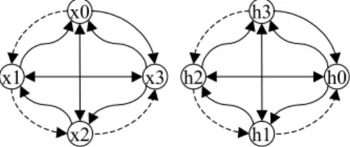
the memory vertices, and W’ is a function that represents the access delay between two data nodes. W’ has only two possible values: Wseq (sequential) for an adjacent memory access in memory, or Wrand (randomize) for a non adja-cent memory access. Weight depends on the data place-ment defined in the memory file. Fig. 1 shows a memory constraint graph for the LMS filter with two simple port memory banks. The input samples x(i) are placed consec-utively in one bank. The filter coefficients h(i) are placed consecutively in one another bank (dotted edges represent edges where W = Wseq).
x0 x1 x2 x3 h3 h2 h1 h0
Figure 1: Memory constraint graph for a 4 points LMS
The classical list scheduling algorithm relies on heuristics in which ready operations (operations to be scheduled) are listed by priority order. In our tool, an early scheduling is performed. In this scheduling, the priority function depends on the mobility criterion. This mobility is computed, for each cycle, as the difference, in number of cycles, between the current cycle and the operation deadline. Whenever two ready operations need to access the same resource (this is a so called resource conflict), the operation with the lower mo-bility has the highest priority and is scheduled. The other is postponed. To perform a scheduling under memory con-straint, we introduce fictive memory access operators and add an accessibility criterion based on the MCG. A memory has as much access operators as access ports. The mem-ory is declared accessible if one of its fictive memmem-ory ac-cess operators is idle. Several operations can try to acac-cess the same memory in the same cycle; accessibility is used to determine which operations are really executable. Fic-tive memory access operators are represented by tokens on the MCG. There are as many tokens in the MCG as ports (R/W) in the memory. These tokens are used to compute the accessibility of the memory. The list of ready operations is still organized according to the mobility criterion, but all the operations that do not match the accessibility condition are removed from this list. To schedule an operation that involves an access to the memory, we check if the data is not in a busy memory bank. If a memory bank is not available, every operation that needs to access this memory will not be scheduled, no matter its priority level.
3.
RESULTS
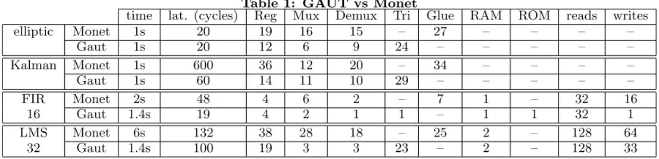
Several syntheses were performed, both with GAUT and the industrial behavioral synthesis tool Monet. We chose the elliptic and the Kalman filters which are the biggest applications in the HLSynth’92 benchmarks, and two classi-cal digital algorithms: a FIR filter and an echo cancellation
algorithm, the LMS. Table 1, indicates the synthesis time in seconds and the architecture’s latency in number of cy-cles (the same real-time constraint was given to the tools, the clock cycle is 10ns). Required hardware resources are also indicated: the number of registers (Reg), of multiplex-ers (Mux), demultiplexmultiplex-ers (Demux), of glue logic elements (which are tri-states in GAUT), and the number of RAM and ROM memories. The two last columns give the number of read and write in those memories. Single port SRAM were used to store data. Syntheses were executed on SUN Blade 2000 workstations.
Hardware resources are always lower in architectures syn-thesized with GAUT, although the same number of arith-metic operators is needed. The latency, which is the delay between the input of the first data and the first result on the output, is also lower with GAUT. It is necessary to distin-guish three sorts of data in a signal processing application. First, there are the signals, which are the input and out-put flows of the applications. A mono-dimensional signal xis a vector of size n, if n values of x are needed to com-pute the result. Every cycle, a new value for x (x[n + 1]) is sampled on the input, and the oldest value of x (x[0]) is discarded. We called x an ageing, or maturing, vector or data. Second, there are the static coefficients, whose value is never changed. We chose to store these coefficients in ROM with GAUT, whereas they are wired with Monet. That ex-plains why a ROM is needed with GAUT for the FIR filter, and not with Monet. Third, we consider the dynamic co-efficients, whose value is changed during the execution of the algorithm, which is the case for an adaptative filtering like the LMS. Dynamic coefficients and ageing vectors are stored in RAM. In Monet, the new value of a signal is always written at the same address in memory, at the end of the vector in the case of a 1D signal for instance. That involves to shift every other values of the signal in the memory to free the place for the new value. This shifting necessitates nreads and n writes in the memory (and this is really time and power consuming). In GAUT, the new value is stored at the address of the oldest one in the vector. Only one write is needed. Obviously, the address generation is more difficult in this case, because the addresses of the samples called in the algorithm change from on cycle to the other. We have developed a new methodology to resolve the syn-thesis of these address generators. The advantage is a lower latency, since we avoid n reads and writes of the ageing vec-tor, and a resulting lower power consumption. Indeed, the power consumption of a memory increases with the number of accesses.
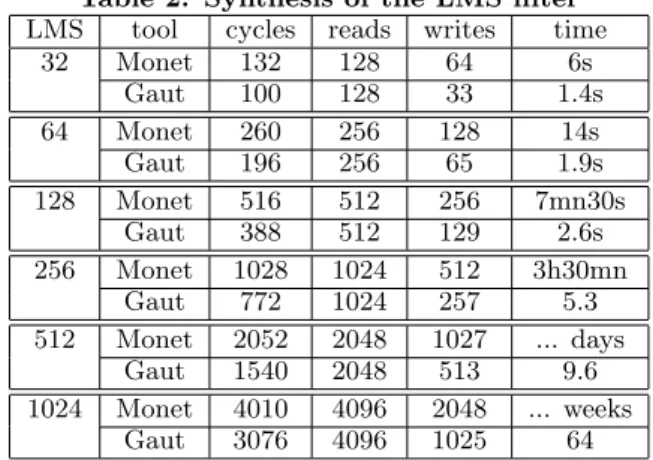
The synthesis time, together with the reduction of hard-ware resources and memory accesses, exhibit the efficiency of our scheduling technique. In fact, the difference between the synthesis time with GAUT and with a behavioral synthesizer like Monet increases with the complexity of the application. We have measured the synthesis times for the FIR and the LMS filters, with an increasing complexity. Table 2 presents the results for the LMS for 16, 32, 64, 128, 256, 512, and 1024 points. It can be observed that, even if the difference between the synthesis time with GAUT and Monet is rel-atively small for small designs, it becomes enormous when the design’s complexity increases. Indeed, it becomes hours, then days or weeks for the FIR 1024 and the LMS 512 and 1024. In fact, every memory access is a node to be schedule in Monet, and the scheduling algorithm has a strong
com-plexity. The difference in latency is comparatively stable: the latency with Monet varies from about 2 to 3 times the latency with GAUT.
Table 2: Synthesis of the LMS filter LMS tool cycles reads writes time
32 Monet 132 128 64 6s Gaut 100 128 33 1.4s 64 Monet 260 256 128 14s Gaut 196 256 65 1.9s 128 Monet 516 512 256 7mn30s Gaut 388 512 129 2.6s 256 Monet 1028 1024 512 3h30mn Gaut 772 1024 257 5.3 512 Monet 2052 2048 1027 ... days Gaut 1540 2048 513 9.6 1024 Monet 4010 4096 2048 ... weeks Gaut 3076 4096 1025 64
With the help of GAUT, it is easy to find the minimum number of operators and memory banks to satisfy the ap-plication’s timing constraint. The results for a 32 points FFT are presented on Fig. 2. The application’s data rate is given to the tool as the input data stream delay. When the data rate decreases, the number of simultaneous memory accesses, and so the number of memory banks, increases, as well as the number of operators. Given a number of banks, it is thus possible to find the minimum data rate, which is reached when the scheduling generates more simultaneous memory accesses than available memory access operators. In this case, the number of operating resources is also the biggest. 0 1 2 3 4 5 6 7 0.89 1.02 1.21 1.38 1.5 1.98 2.74 2.93 5.81 7.66 ALU MULT Number of resources Data Rate (µs)
8 banks 4 banks 2 banks 1 bank
Figure 2: Resource number vs. Data rate
Once found the required number of operators, one can try different numbers of memory banks as well as several data mappings, and evaluate their impact on the final applica-tion’s performance and power consumption. In our exam-ple, for a data rate equals to 7.66s, we decide to allocate one multiplier and two ALU, and to share the memory in two banks.
We then apply several memory mappings to the synthesis process, and observe the impact on the resulting circuit’s power consumption. The circuit is a FPGA Xilinx Virtex XC400. Its consumption is computed with the Xilinx tool:
Table 1: GAUT vs Monet
time lat. (cycles) Reg Mux Demux Tri Glue RAM ROM reads writes
elliptic Monet 1s 20 19 16 15 – 27 – – – – Gaut 1s 20 12 6 9 24 – – – – – Kalman Monet 1s 600 36 12 20 – 34 – – – – Gaut 1s 60 14 11 10 29 – – – – – FIR Monet 2s 48 4 6 2 – 7 1 – 32 16 16 Gaut 1.4s 19 4 2 1 1 – 1 1 32 1 LMS Monet 6s 132 38 28 18 – 25 2 – 128 64 32 Gaut 1.4s 100 19 3 3 23 – 2 – 128 33
XPower. One memory unit is generated for each mem-ory mapping. The memmem-ory unit power consumption Pmu is provided in Table 3, together with the overall consump-tion Ptot, and the processing unit consumpconsump-tion Ppu. In the map2 16 mapping, the first sixteen real and imaginary FFT samples are mapped in the first bank, the remaining sixteen samples are in the second bank. In the map2 8, map2 4, and map2 2 mappings, samples are mapped respectively 8 by 8, 4 by 4, and 2 by 2, in the first and second memory banks. In the map2 1 mapping, even samples are in the first bank, odd samples in the second.
Table 3: Power consumption
Power (mW) Pmu Ppu Ptot ∆ Ptot % map2 16 (2banks) 12.71 34.35 47.06 ...
map2 8 (2banks) 12.83 21.85 34.68 -26 map2 4 (2banks) 12.9 17.77 30.67 -35 map2 2 (2banks) 12.99 21.63 34.62 -26 map2 1 (2banks) 12.87 19.26 32.13 -31
Every memory unit invariably contains 2 RAM, and 4 FSM to drive the write and read accesses between the busses and the RAM. As a result, and because the number of mem-ory accesses is also constant, there are very few variations on the memory unit power consumption (less than 2.5%, only due to small changes in I/O signals commutations and some logic blocs). Variations of the processing unit consumption are much more important, for they represent from 58% to 64.1% of the overall power consumption. The lowest over-all consumption is obtained with the map2 4 mapping (35% lower than the map2 16), even if the memory unit consump-tion is slightly higher in this case (1.5%) than the lowest one.
4.
CONCLUSION
In this paper, we present a new strategy to take into ac-count the memory architecture and the memory mapping in High-Level Synthesis. We define the memory mapping con-straint and include it in the synthesis design flow. We intro-duce Memory Constraint Graphs, and an accessibility crite-rion to enhance the scheduling algorithm. Our method was included in GAUT, the HLS tool developed in the LESTER Laboratory. Several experiments were made, to explore the efficiency of our approach. The comparison with an indus-trial behavioral synthesis tool exhibits several advantages for GAUT. It appears firstly that GAUT uses less hardware resources, and reduces the count of memory accesses, which lead to a lower latency and a lower power consumption.
Sec-ondly, GAUT is able to tackle complex designs, and to per-form the synthesis in a reasonable time. Memory aware synthesis and GAUT appear very efficient for exploring the design space and for balancing optimizations between the processing unit and the memory unit. It permits to deter-mine the best memory architecture, i.e. the best number of memory banks, as well as the best memory mapping, to meet the application constraints.
5.
REFERENCES
[1] P. Ellervee. High-Level Synthesis of Control and Memory Intensive Applications. PhD thesis, Royal Institut of Technology, Jan. 2000.
[2] C. Gebotys. Low energy memory and register allocation using network flow. In Proc. Design Automation Conference DAC’97, pages 435–440, June 1997. [3] D. Knapp, T. Lyand, et al. Behavioral synthesis
methodology for HDL-based specification and validation. In Proc. Design Automation Conference DAC’95, June 1995.
[4] H. Ly, D. Knapp, R. Miller, and D. McMillen.
Scheduling using behavioral templates. In Proc. Design Automation Conference DAC’95, pages 101–106, June 1995.
[5] A. Nicolau and S. Novack. Trailblazing a hierarchical approach to percolation scheduling. In Proc. ICPP’93, pages 120–124, 1993.
[6] N. Passos, E. Sha, and L.-F. Chao. Multi-dimensional interleaving for time-and-memory design optimization. In Proc. IEEE Int. Conf. On Computer Design ICCD’95, pages 440–445, Oct. 1995.
[7] R. Saied and C. Chakrabarti. Scheduling for minimizing the number of memory accesses in low power applications. In Proc. VLSI Signal Processing, pages 169–178, Oct. 1996.
[8] J. Seo, T. Kim, and P. Panda. An integrated algorithm for memory allocation and assignment in high-level synthesis. In Proc. Design Automation Conference DAC’01, pages 608–611, June 2001.