1
Simplified analytical method for estimating the resistance of lock
gates to ship impacts
Loïc Buldgen
1, Hervé Le Sourne
2, Philippe Rigo
31 University of Liège, ANAST, 1 Chemin des Chevreuils, 4000 Liège, Belgium – L.Buldgen@ulg.ac.be 2 ICAM Nantes, 35 Avenue du champ de Manœuvres, 44470 Carquefou, France – herve.lesourne@icam.fr 3 University of Liège, ANAST, 1 Chemin des Chevreuils, 4000 Liège, Belgium – ph.rigo@ulg.ac.be
Corresponding author: Loïc Buldgen Phone : +32 (0)4 366 48 59 Mobile : +32 (0)478 50 21 88 Fax : +32 (0)4 366 91 33 Mail : L.Buldgen@ulg.ac.be
Address : University of Liège, Faculty of Applied Sciences, ANAST, 1 Chemin des Chevreuils, 4000 Liège, Belgium
Abstract
The present paper is concerned with the design of lock gates submitted to ship impacts. In this article, a simplified analytical method is presented to evaluate the resistance of such structures under collision. The basic idea is to assume that the resistance is first provided through a local deforming mode, corresponding to a localized crushing of some impacted structural elements. For consecutive larger deformations, the resistance is then mostly provided through a global deforming mode corresponding to an overall movement of the entire gate.
For assessing the resistance in the case of the local deforming mode, the structure is divided into a given number of large structural entities called “super-elements”. For each of them, a relation between the resistance of the gate and the penetration of the striking ship is established. However, as some results are already available in the literature, this subject is not treated extensively in this paper. On the contrary, the calculation of the resistance of the gate provided through the global mode is detailed and the strategy to switch from local to global deformation is highlighted.
Finally, we propose to validate our developments by making a comparison between results obtained numerically and those predicted by the present analytical approach.
2
1.
Introduction
Amongst all the loads which have to be expected for the design of lock gates, the collision of a vessel is one of the most difficult to handle with.
A collision may result in some minor damages to the plating or to the stiffening system of the gate, producing for example a local loss of water tightness. However, if the initial velocity of the striking ship is large enough, the displacements imposed to the structure may cause a complete collapse of the gate. This would result in the emptying of the damaged reach, with probably the complete sinking of the striking ship.
To deal properly with ship impact, it is of course possible to use nonlinear finite element methods. Nevertheless, at the pre-design stage of a gate, such approaches are rather restrictive because of the time required to model and simulate collisions. Therefore, we propose here to establish an analytical simplified method in order to verify the resistance of gates submitted to a ship impact.
For the moment, the development of such simplified methods is not really reported in the literature. Some very interesting results have been established for the purpose of analyzing collisions between two ships. For example, the crushing resistance of web girders has already been theoretically and experimentally studied by Wierzbicki and Culbertson-Driscoll [1], Wang and Ohtsubo [2], Simonsen [3], Zhang [4] and Hong and Amdahl [5]. Each of them developed analytical formulations that may be useful for studying locally the contact between a ship and a gate.
Additional results are also available for impacted panels, which have been investigated in details by Wang [6], Wang and Ohtsubo [7] and Zhang [8]. Some references are also useful for evaluating the resistance of metal plates after rupture, when they are submitted to tearing and cutting. For example, these phenomena have been studied by Wang and Ohtsubo [7], Zhang [8], Wierzbicki [9] and Zheng [10]. In the particular case of stiffened panels subjected to lateral loads, the developments performed by Paik [11], Cho and Lee [12] or Ueda, Rashed and Paik [13] constitute a very accurate basis for performing analytical estimation of the resistance of such structural components.
The previous brief literature review shows that some results are already available to deal with a simplified approach of collisions between ships and gates. All these developments constitute of course an invaluable help for developing simplified collision models of lock gates, but they are not sufficient. The principal reason is that the behavior of an impacted gate may not directly be assimilated to the one of an impacted vessel. Consequently, some researches in this domain are still needed.
The aim is to develop some analysis tools, which would be time and cost-effective in the pre-design stage of gates. To achieve this goal, we will follow a similar method than the one proposed by Le Sourne, Rodet and Clanet [14]. The basic idea is that the total resistance of the struck gate is provided by two deforming modes:
- the local one, which implies a local crushing of all the impacted structural elements; - the global one, which supposes an overall deformation of the gate.
3
2.
General description of the problem
In this paper, we consider the exceptional situation of ship colliding with a lock gate. The collision scenario is depicted on Figure 1, where the general coordinate system is denoted by ( , , ). For avoiding confusion in the present text, we will use the terminology “transversal”, “vertical” and “longitudinal” in accordance with the respective orientation of ,
and axes.
In our scenario, the vessel is coming from upstream and, consequently, the impact is located on the downstream gate of the lock. It is clear that this case is the least desired, because the hydrostatic pressure is acting in same direction as the impact force. On the contrary, if the collision was happening in the downstream reach of the lock, the resulting hydrostatic pressure would act in opposition with the impact force and would compensate it partially.
Figure 1 – Plane and section views of the impact situation
In order to derive an analytic procedure for estimating the collision resistance of the gate, we first need to describe the ship and the gate using various parameters. This is the purpose of the subsequent sections.
2.1. Geometrical description of the striking vessel
The vessel is characterized through the following: mass and velocity . In other words, we assume a certain kinetic energy /2 for the striking ship. These two parameters are chosen according to the waterway class, which determine the maximal speed as well as the allowable shipping of the vessels.
4 The geometric point of view, we first assume that the shape of the bow at the uppermost deck may be fairly modeled by a parabola Γ (see Figure 1) having a transversal radius and a longitudinal radius . Consequently, in the local axes ( , ) positioned in point , the equation of the curve Γ is given by:
Γ ≡ = ∙ 1 − (1)
In order to have a global description of the geometry of the ship, it is also required to introduce the following parameters (see also Figure 1):
- the height ℎ between the uppermost deck and the bottom of the ship;
- the side angle and the stem angle , which are used to fix the inclination of the bow. It is important to note that all the above mentioned properties are required input data, which have to be provided by the user before the beginning of the calculation process.
2.2. Description of the gate
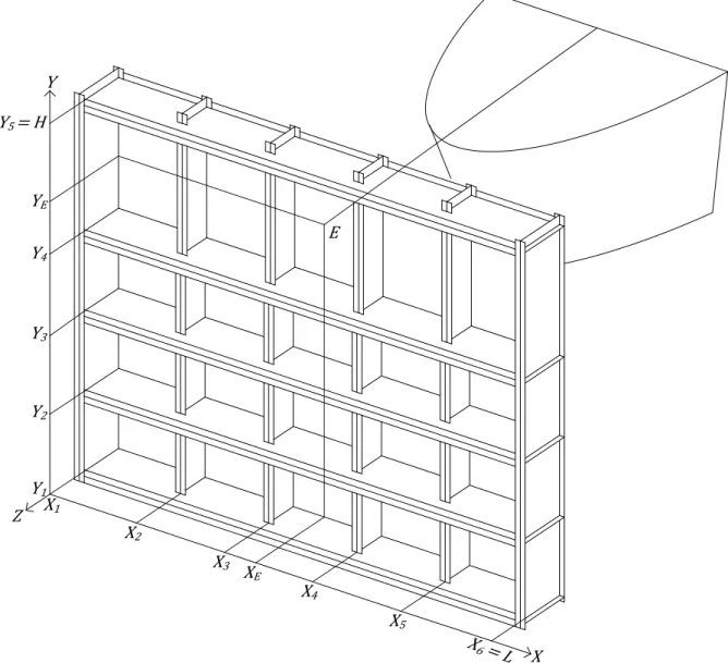
5 In this paper, we will only focus on gates with a single plating. A three dimensional picture of such a structure is depicted on Figure 2, where the notations and are used for representing respectively the total vertical and the total transversal extension of the gate. In fact, these gates are rather similar to large orthotropic plates, constituted by a plating (for retaining water) stiffened by the following elements (see Figure 2 and Figure 3):
- the transversal frames, which may be seen as beams presenting a T-shaped cross-section. They are placed in the transversal direction (i.e. along the axis).
- the vertical frames, which are also beams with a T-shaped cross-section, but are arranged in the vertical direction (i.e. along the axis).
- the stiffeners, which are optional reinforcing beams disposed transversally on the plating in order to avoid instabilities in shells. Their cross section may exhibit various shapes.
6 The geometric data required for characterizing the stiffening system are mainly the dimensions of the different cross-sections. As shown on Figure 3, the needed values are the height ℎ and thickness ! of the web, as well as the height ℎ" and thickness !" of the flange. For the plating, it is only necessary to precise its thickness !#. With all these parameters and knowing the properties of the material constituting the gate, it is possible to derive the mechanical properties of all the stiffening elements.
Another point which has to be clarified concerns the assumed support conditions of the structure. When the gate is closed, the contact is supposed to be established against the support denoted $%, $ and $& on Figure 3 and, consequently, we may admit that:
- the gate is simply applied against the two lock walls (supports $% and $ on Figure 3). The translational degree of freedom in the direction has therefore to be blocked along the all vertical extension of the gate in $% and $ .
- the gate is simply applied against the sill located at the bottom of the chamber (support $& on Figure 3). Therefore, it seems to be reasonable to restrain the translational displacement in the direction along the all transversal extension of the gate in $&.
2.3. Description of the material
The present article is concerned with the resistance of a lock gate impacted by a ship. The primary goal is not to assess the damages caused to the vessel: we are much more interested by the ability aspect of the structural resistance to collisions. As a consequence, we assume that the material constituting of the striking vessel is infinitely rigid. In other words, we won’t allow any deformation in the ship’s structure, which is a conservative approach in the evaluation of the resistance.
On the contrary, the previous hypothesis is not valid for the gate, as it is supposed to be deformable. Nowadays, the most common material used for such structures is construction steel, so we will only deal with this material in the present paper. This kind of steel exhibits a constructive law represented by curve (1) on Figure 4 and may be defined by the following parameters:
- the maximal elastic stress ' , to which is associated the maximal elastic deformation ( - the rupture stress '), for which tearing is observed in the material. The corresponding
deformation is called ().
- the Young’s modulus * characterizing the stiffness of the material during the elastic phase.
7 In order to simplify the analytical derivation of the collision resistance, we will suppose here that the steel has a so called “elastic-perfectly plastic” behavior. This means that the relation between stresses and strains is idealized by curve (2) on Figure 4. Consequently, we neglect the additional resistance coming from hardening of steel, which is in fact a conservative assumption.
2.4. General positioning in the space
To define the collision scenario, it is still necessary to position the resistance element as well as the striking ship within the area of space. To do so, different kinds of input data are still required:
- the impact point *, i.e. the point of the gate where the first contact between the bow and the plating will be established. This point is located by its coordinate ( +, +), as shown on Figure 5 and Figure 6.
Figure 5 – Position of the resistance elements and of the impact point
- the transversal positions , of the vertical frames, i.e. the position of each vertical frame along axis (see Figure 5).
- the vertical positions , of the horizontal frames, i.e. the position of each horizontal frame along axis (see Figure 5).
8 - the total number of stiffeners distributed along the vertical height of the gate.
When all the previous inputs are placed, the three dimensional configuration of the gate is completely defined.
3.
Methodology for evaluating the collision resistance
3.1. General principles
When a ship collides with a gate, its action on the impacted structure may be represented by a force -. acting in the same direction as the indentation / of the striking vessel (see Figure 6). By equilibrium, this force may be seen as the resistance opposed by the gate to the progression of the ship. Therefore, the goal of our work is to assess the value of -. for a given indentation / of the vessel. In other words, our aim is to derive the evolution of -. with / by means of simplified analytical procedures.
Figure 6 – Representation of the impact force
When a ship is entering into a lock, it seems reasonable to admit that its initial velocity is quite small. Consequently, the dynamic effects in the gate remain moderate, and we may assume that the initial kinetic energy /2 of the ship is entirely dissipated by deformation of the impacted gate *,0., i.e.:
1
2 = *,0. (2)
Knowing the relation between -. and /, it is possible to calculate *,0. simply by integration (see Figure 7):
*,0. = 1 -.(/) ∙ 2/ 3456
9 For a given ship of mass and velocity , equations (2) and (3) give the maximal penetration /789 which has to be supported by the gate to withstand to an impact with such a vessel. According to the maximal degradation level accepted for the gate, it can be decided if this value of /789 may be applicable or not.
3.2. Theoretical basis
The theoretical basis for deriving -.(/) is the so-called “upper-bound theorem”, which states that “if the work rate of a system of applied loads during any kinematically admissible collapse of a structure is equated to the corresponding internal energy dissipation rate, then that system of loads will cause collapse, or incipient collapse, of the structure”.
Figure 7 – Evolution of the resistance of the gate with the penetration of the ship
In the present case, it is obvious that the external dissimilation rate *:;9. is entirely produced by the force -. applied by the ship on the gate. Therefore, we have:
*:;9.= -. = -./: (4)
where < : = = >/>! is the derivative with respect to time. On the other hand, if we neglect dynamic effects in the structure, the internal dissipation rate *:,0. is entirely coming from the deformation of the gate. If ? is the total volume of the structure, using the Einstein’s notation we have:
*:,0. = @ ',A(:,A2 2 2 ?
(5)
where ',A and (:,A are respectively the stress and the strain rate tensors defined over the entire volume ? of the gate. By application of the upper-bound theorem, we have:
*:;9.= *:,0.⇒ -. =1/:@ ',A(:,A2 2 2 ?
(6)
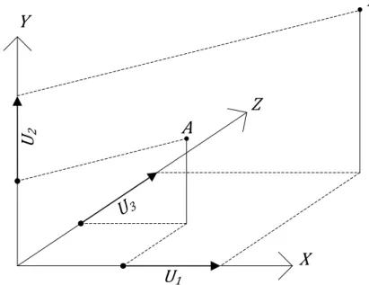
Consequently, equation (6) may be useful for deriving -.(/), provided that we are able to establish a relation between the deformation rate (:,A and the velocity /:. To do so, we need to define the displacements over the entire volume ?. For example, on Figure 8, if we suppose that point is moving to point C for a given value of /, we may define the three components D%( , , , /), D ( , , , /) and D&( , , , /) of the displacement field along axis , or
10 respectively. Note that in the remaining part of this paper, we will also use the equivalent notations (D, , E) and ( %, , &) for designating (D%, D , D&) and ( , , ).
Figure 8 – Definition of the displacement field
Using the Green-Lagrange tensor, it is finally possible to find a link between the deformation and the penetration of the ship /:
(,A=12 >D> , A+ >DA > ,+ >DG > , >DG > A (7)
Equation (7) may be rewritten in the following shorter form:
(,A = H,A( , , , /) ⟺ (:,A=>H>/ /,A : (8) If we want to apply formula (6) to obtain a relation between -. and /, it is also required to evaluate the stresses ',A as a function of /. This may be achieved using the constitutive laws giving a relation between ',A and (,A. As the evolution of (,A with / is known by equation (7), we also have:
',A = J,A( , , , /) (9)
Note that D%, D and D& are unknown; for a given value of /, we have to postulate a certain displacement field. Provided that this displacement field is kinematically admissible, we may apply the upper-bound theorem and calculate the resistance -. with formula (6). In fact, if we combine (8) and (9) in (6), we obtain:
-. = @ J,A( , , , /)>H>/ 2 2 2,A ?
(10)
Equation (10) is the needed relation between -. and /. However, the crucial point in the above-described approach is to define properly a kinematically admissible displacement field, otherwise the upper-bound theorem may lead to an overestimation of the crushing resistance.
11
3.3. The super-elements method
The integration of equation (10) has to be performed over the whole volume ? of the struck structure and is rather impossible to derive analytically. As a consequence, we need to simplify the procedure described here over, and this may be achieved by splitting the gate into super-elements.
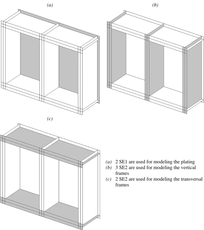
The basic idea is to divide the gate into different substructures (so called “super-elements”) that we assume working independently. For the lock gate depicted on Figure 2, the structure may be decomposed into two types of super-elements:
The first super-element (SE1) is a rectangular plate simply supported on its four edges and impacted perpendicularly to its plane, undergoing therefore important out-of-plane displacements. Such elements are typically used for modeling the plating of the gate. The second super-element (SE2) is a beam with a T-shaped cross-section, impacted in its plane. This kind of element is therefore quite relevant for modeling transversal and horizontal frames.
The division of the gate into super-elements is only based on geometric considerations. In order to illustrate this process, we can consider for example only a small part of the lock gate represented on Figure 2, for which the division principle is shown on Figure 9. As it can be seen, the two previous types of elements are sufficient for analyzing the structure.
As long as there is no contact between the ship and a given super-element, this latter will remain inactive. This means that it will not deform until it has been collided by the bow, which is a consequence of the above-mentioned hypothesis that each substructure is working independently. After being activated, the super-element will deform and dissipate a certain amount of energy. If the gate is divided into K super-elements, as each of them is decoupled from the others, the total internal energy *,0. is simply obtained by summation of the individual contributions coming from the K super-elements, i.e.:
*,0. = L *,0.(G) 0 GM% ⇒ *:,0.= L *:,0.(G) 0 GM% O ∈ Q1, … , KS (11)
where *,0.(G) is the internal energy dissipated by super-element n°O for a given penetration / of the ship. Before using equation (11), it is preliminary required to know *:,0.(G). To do so, formula (5) is still valid, but it has to be re-equated for the case of super-element O:
*:,0.(G)= @ ',A(G)∙ (:,A(G)∙ 2 2 2 ?T
O ∈ Q1, … , KS (12)
where we have introduced the following notations:
',A(G) stress tensor defined on the entire volume of super-element O (:,A(G) strain rate tensor defined on the entire volume of super-element O ?G volume of super-element O
12
(a) (b)
(c)
(a) 2 SE1 are used for modeling the plating
(b) 3 SE2 are used for modeling the vertical frames
(c) 2 SE2 are used for modeling the transversal frames
Figure 9 – Illustration of the subdivision of a structure into super-elements
By following a similar reasoning as for relations (8) and (9), we get finally the particularization of equation (10): -.(G)= @ J,A(G)∙>H,A (G) >/ ∙ 2 2 2 ?T ⇒ -. = L @ J,A(G)∙ >H,A(G) >/ ∙ 2 2 2 ?T 0 GM% (13)
where -.(G) may be seen as the contribution of super-element O to the total resistance of the gate (note that Einstein’s notation has been used for the subscripts U and V). In fact, relation (13) is of primary importance because it constitutes the fundamental basis of the present
13 method. Of course, we still need to develop adequately the functions involved in this expression. This will be done later for SE1 and SE2.
3.4. Global and local deforming modes
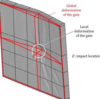
We previously assumed that each super-element was working independently from the others. This hypothesis remains valid as long as the penetration / is reasonably minor. However, when the penetration / of the ship is increasing, deformations will occur in super-elements which still have not been undertaken by the bow. Consequently, the internal energy rate for super-element O may not be equal to zero, although it has not been activated. This may be seen on Figure 10, where out-of-plane displacements occur in the entire gate, even if some regions have not been impacted by the striking ship bow.
Figure 10 – Illustration of global and local deformations
In order to take this coupling into account, let us introduce the concept of local and global deforming modes.
We say that the structure exhibits a local deforming mode (see Figure 10) when the developments performed in section 3.3 may be applied. In other words, we suppose here that the penetration of the vessel into the gate is only allowed by the local deformations of the activated super-elements. Only the area impacted by the ship contributes to the energy dissipation; the other parts of the gate remain undeformed. Of course, it may be easily understood that the local mode is only valid for quite small values of /.
On the contrary, we say that the structure exhibits a global deforming mode (see Figure 10) when the displacements are not confined in a small area located around the impact point. In this case, the entire gate is involved in the energy dissipation process and we may no longer assume that it behaves like a set of independent substructures activated progressively. Consequently, the super-elements method is not valid anymore and the
14 resisting force -. has to be evaluated by another way than the one discussed in section 3.3. This is precisely the topic of section 5.
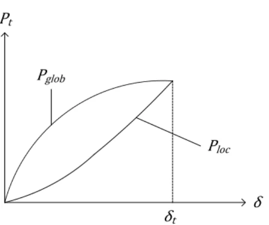
In order to model the phenomena depicted on Figure 10, we suppose that there is a sudden switch between the two modes. At the beginning, when the striking ship starts moving into the gate, the resistance -. is essentially provided by the local deforming mode. This statement remains valid as long as the penetration / does not exceed a transition value /., for which the global mode is activated. In fact, the switch between the two modes occurs when the force -. applied by the ship on the gate is sufficient to cause an overall displacement of the whole structure. As soon as / ≤ /. two different values for -., are computed:
- the value of -. obtained by supposing a local deforming mode. It is denoted by -XYZ. - the value of -. obtained by supposing a global deforming mode. It is denoted by -[XY .
Figure 11 – Evaluation of the transition from the local to the global mode
For a given penetration /, -XYZ and -[XY are then compared. As long as -XYZ < -[XY , the force exerted locally by the ship is not sufficient to cause an overall displacement of the gate, so the ship continues penetrating into the structure by local indentation. However, as soon as -XYZ = -[XY , the force becomes sufficient enough and the switch from the local mode to the global one is obtained. The corresponding value of / is the required /. (see Figure 11). After that, for the values of / greater than /., the resistance -. is evaluated using equations specially developed for the global mode (see section 5).
4.
Evaluation of the resistance in the local deforming mode
In the local deforming mode, the resistance of the gate is given by equation (13), where we assume that the total resisting force is simply obtained by adding the individual contributions of all the activated substructures. In this section, the laws governing the behavior of the two types of super-elements introduced in section 3.3 are detailed. However, as this topic is already well-treated in the literature (see for instance [18]), in order to avoid any redundancy, we have made a quite concise presentation of our approach.
Note: in the two following sections, we will use the superscript (O) for characterizing any
property of the super-element number O.
4.1. Super-element type 1 (SE1)
The first super-element is used for modeling the plating of the lock gate. Its boundaries are defined by the surrounding transversal and vertical frames, as shown on Figure 12.
15 Considering the location of the impact point *, it is possible to fix the four parameters ]%(G), ](G), ^%(G) and ^(G).
Figure 12 – Definition of the main dimensions of SE1
The thickness of the plate is equal to the thickness !# of the plating. However, a correction is needed for taking into account the horizontal stiffeners placed in the transversal direction. During the collision, the stiffeners are mainly submitted to an axial extension; they will deform along the direction by exhibiting a membrane behavior. Consequently, the plate thickness has to be modified for taking these effects into account. If _ is the total area of all the stiffeners connected to the super-element O (see Figure 13), then we obtain:
!`(G)= !#+ _ (G)
^%(G)+ ^(G) (14)
This correction has to be applied for the calculation of membrane effects in the direction. However, if we consider membrane effects in the direction, the stiffeners have no influence and they do not need to be considered. Consequently, we have !a(G)= !# and the plate becomes orthotropic.
Figure 13 – Equivalent plate thickness
In the present approach, we suppose that the impacted plate is completely independent from the surrounding other super-elements. Therefore, it is acceptable to consider the plate as
16 simply supported on its four edges. For a given indentation /, the super-element will undergo mostly a membrane deformation; the effects of bending remain negligible.
When super-element SE1 is impacted by the bow of the vessel, for a given value of /, we may deduct the deformation pattern shown on Figure 14. With this displacements field, it is possible to evaluate the internal energy rate, which has already been done by Zhang [4].
Figure 14 – Displacement field assumed for SE1
For the situation illustrated in Figure 14, Zhang (1999) found the following crushing resistance for super-element O:
-.(G)=2√3' d]%(G)+ ](G)e d^%(G)+ ^(G)e f !` (G) ]%(G)](G)+
!a(G)
^%(G)^(G)g (15)
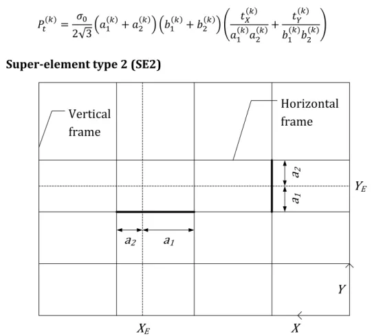
4.2. Super-element type 2 (SE2)
Figure 15 – Definition of the main dimensions of SE2
The second super-element that we will consider is used for modeling the transversal and vertical frames. The boundaries of a horizontal super-element are defined by the two adjacent vertical frames (and inversely for a vertical super-element).
17 The principal dimensions ]%(G) and ](G) (see Figure 15) of super-element O are positioned in accordance with the location of the impact point. The resisting cross-section has a T-shape, whose properties are defined in the general geometry of the gate.
When this super-element is impacted, we suppose that it will deform like a concertina. To do so, three plastic hinges are formed. They are designated by Ch, ih and jh on Figure 16. These lines allow for relative rotation between the triangular surfaces Ci, ij, Cih and hij. Bending effects are therefore preponderant along these lines.
However, the rotational movement of the triangular surfaces is not free because it must respect the compatibility between surfaces Cj and Chj along their common line Cj. Therefore, surfaces Cj and Chj are submitted to an axial extension implying mainly membrane effects. Consequently, for a given indentation /, the web will be folded as represented in Figure 16, where 2 is the total height of one fold. According to the previous hypothesis, during this motion, the energy is absorbed by membrane extension of the triangular regions Cj and Chj, but also by bending effects in the three plastic hinges Ch, ih and jh. The phenomenon of concertina folding has already been studied by a great number of authors. For example, it was theoretically and experimentally studied by Wierzbicki and Culbertson-Driscoll [1], Wang and Ohtsubo [2], Simonsen [3] and Zhang [4]. Hong and Amdahl [5] compared all these various approaches and also developed their own model.
Figure 16 – Displacements field assumed for SE2
According to the developments performed by Zhang [4], for a given penetration /, the resistance of super-element n°O is to be taken as:
-.(G)=' ! (G) √3 d^% (G)+ ^(G)e ∙ f!(G) √ /+ 4 3^%(G)^/(G) g (16) where !(G) is the web thickness of super-element O. In this formula, is a parameter fixed by minimizing the mean crushing resistance over one fold. By so doing, Zhang [4] found that:
18
4.3. Total resistance in local deforming mode
The total resistance of the gate in the local deforming mode is simply obtained by summing the individual contributions of the K super-elements:
-XYZ = L -.(G) 0 GM%
(18)
Of course, for a given value of /, if a super-element hasn’t been activated, it will not provide any resistance to the total resistance, and so we have:
-.(G)= 0 (19)
5.
Evaluation of the resistance in the global deforming mode
5.1. Displacements fields
When the global mode is activated, the gate is assumed to undergo a global motion involving the entire structure. The displacements field obtained in this case is plotted on Figure 17a. As mentioned earlier, the first contact between the bow and the plating is located in point *, with coordinates ( +, +, 0). In the vertical plan passing through this point (i.e. the plan with equation = +), we suppose that the displacements are distributed along the vertical axis as shown on Figure 17b. The mathematical formulation of this profile is as follow:
E+( , /) = / ∙
+ if 0 ≤ < + (20)
E+( , /) = / if +≤ ≤ (21)
where E+ indicates that we consider the displacement in the plan = +.
The two previous formulae are only valid as long as there is no other contact between the ship and the gate. However, as the vessel is moving forward, another contact will appear between the plating and the lowermost deck (see Figure 18). The particular value of / for which this situation will occur is denoted /Z and we have:
/Z = +∙ cot (22)
where is the stem angle. When / ≥ /Z, the contact between the bow and the plating is completely developed along the height ℎ (see Figure 18). Consequently, it is required to adapt the previous displacements fields in order to account for this phenomenon. Then, for / ≥ /Z, we will use the following equations:
E+( , /) = (/ − ℎ cot ) ∙
+− ℎ if 0 ≤ < +− ℎ (23)
E+( , /) = / + ( − +) cot if +− ℎ ≤ < + (24)
19
(a) (b)
Figure 17 – (a) Assumed displacements field; (b) Displacement profile in the plan X = XE
(a) (b)
Figure 18 – Assumed displacements field after second contact between the bow and the plating
5.2. Mechanical model of the gate
In the previous section, we have postulated a kinematically admissible displacements field. In accordance with the upper-bound method, it is now possible to use the principle of virtual velocities in order to estimate the resistance of the structure deformed in the global mode.
20 Unfortunately, it is rather difficult to derive analytically the resistance of a gate submitted to the displacements given by equations (20), (21), (23), (24) and (25). In order to simplify the problem, we make the assumption that the main contribution to the resistance is coming from the bending of the gate between the two lock walls. This hypothesis seems to be reasonable for a global mode, especially when the ratio / is wide, but we have to bear in mind that it may not remain valid in some special cases. As a consequence, the resistance in the global deforming mode is mostly provided by transversal frames the stiffeners. Therefore, the gate may be seen as a set of independent beams subjected to a given displacements field. The contribution of the vertical frames is only to apply the expected displacements to these beams; we suppose that they don’t take part mechanically to the resistance. According to these hypotheses, we obtain the equivalent model of the gate depicted on Figure 19.
Figure 19 – Mechanical model of the gate for assessing the resistance in the global deforming mode
The previous-mentioned beams have a section obtained by taking the gross cross-section of the transversal frames, to which the collaborating part of the plating is added (see the picture at the top of Figure 19). The values of ℎ", !", ℎ , ! , !# are defined as an input of the calculation process, but the collaborating length ^" has to be chosen in order to account for the following phenomena:
21 - the shear lag effect occurring at the junction between the plating and webs of transversal
frames;
- the overall buckling of the stiffened panel located between two transversal frames. This situation corresponds to the configuration (a) plotted on Figure 20.
- the local buckling of the plating located between two stiffeners. This is illustrated by the configuration (b) on Figure 20.
The calculation of the effective width ^;"" (see Figure 20) on both sides of each transversal frame can be achieved by applying the rules provided by Eurocode 3 for longitudinally stiffened plates.
Figure 20 – Calculation of the effective width
Finally, in order to achieve the mechanical modeling of the gate, we still have to give some details about the support conditions of the beams. As they are connected to the vertical frames, they will be mostly restrained at two levels:
- a rotational restriction along the transversal axis, which will hinder the torsional effects in the beams;
- a translational restriction along the longitudinal axis, which will hinder out-of-plane shearing and bending of the beams.
Of course, it is rather difficult to precisely account for these effects in an analytical procedure. As we are not trying to have an accurate resistance of the gate (but a good approximation), it is admissible to consider that each beam is simply supported at both ends. By so doing, we completely omit the additional restrains provided by the vertical frames, which is a conservative hypothesis for evaluating globally the impact resistance.
5.3. Elastic resistance
The mechanical model presented here over is a set of K beams submitted to the displacements fields detailed in section 5.1. In this section, we use the superscript (O) in order to refer to a particular beam, with O ∈ Q1,2 … KS. At the beginning of the impact, a beam located at any given vertical position (G) is deformed according to the classical bending theory (see Figure 21). The deflected shape is then given by a parabola:
E(G)( , /) = + + +− 2 + 2 +( +− ) ∙ E+ (G)(/) = H %( ) ∙ E+(G)(/) if 0 ≤ < + (26) E(G)( , /) = − +− + +− 2 + 2 +( +− ) ∙ E+ (G)(/) = H ( ) ∙ E +(G)(/) if +≤ < (27)
22 where E+(G)(/) = E+( (G), /) and has been defined in section 5.1. The curvature u(G) and the bending moments (G) are obtained using the two following well-known relations:
u(G)=> E
> (G)= *v(G)> E> (28) where * is the elastic modulus and v(G) is the bending inertia of beam O.
Figure 21 – Elastic deformation of a transversal frames
If we only consider the deformation energy arising from the bending of beam O, the internal power defined by (5) can be calculated by:
*:,0.(G)= 1 (G)u:(G)2 w = *v/:E+(G)(/)>E+(G) >/ x1 > H> % `y 2 + 1 > H> wz`y `y 2 { (29)
By introducing (26) and (27) into (29), the individual contribution of beam O to the elastic resistance of the gate in the global deforming mode is defined by:
-.(G)= *v(G)E+(G)(/)>E+ (G)
>/ ∙ +( 3+− )
(30)
5.4. Plastic resistance
Of course, equation (30) remains valid as long as there is no plastic effect in beam O. However, when it is bent beyond its elastic limit, the transversal frame exhibits another kind of behavior, which may be described by using the two following properties:
#(G): the plastic bending moment of beam O, corresponding to a complete plastic cross-section in bending (see Figure 22a);
|#(G): the normal plastic force of beam O, corresponding to a complete plastic cross-section in traction or compression (see Figure 22b).
With these properties, a classical plastic analysis may be performed. As soon as #(G) is reached, the section located in = + behaves like a plastic hinge and the structure becomes a mechanism. At this moment, the yield locus characterizing the cross-section is reached. However, it does not mean that the resistance is not increasing anymore. As the deformations are increasing, tensile stresses appear inside the beam O, and the cross-section is submitted to both a normal force |(G) and a bending moment (G). As they are linked by the equation of the yield locus, these two actions are not independent.
23 In order to evaluate (G) and |(G)for each of the K beams representing the gate, we need more information about plastic interaction. Ueda and Rashed [15] have elaborated a very refined description of the yield locus for the cross-section depicted on Figure 22. However, as suggested by Paik [11], it is easier to adopt a parabolic interaction criterion for beam n°O (see Figure 23): (G) #(G)+ } |(G) |#(G)~ = 1 ⇔ (G)= #(G)− #(G)}| (G) |#(G)~ (31)
Figure 22 – Plastic properties of the cross-section
Figure 23 – Parabolic interaction criterion
If we note Δ(G) and •(G) the axial extension and the rotation in beam O, the required condition of normality is verified for the present yield locus if we have (see Figure 23):
2 (G) 2|(G)= −2Δ (G) 2•(G)= −Δ: (G) •:(G)⇔ − 2 #(G)|(G) d|#(G)e = − Δ:(G) •:(G) (32)
The extensional rate and rotational rates Δ:(G) and •:(G) in beam O may be easily calculated by geometrical considerations based on Figure 24:
•:(G)= ‚1 ++ 1 − +ƒ >E+(G) >/ /: Δ:(G)= E+(/)>E+ (G) >/ ‚1++ 1 − +ƒ /: (33)
By introducing (33) into (32), we finally get a second relation between (G) and |(G). We then obtain the classical formula giving the membrane force in an axially restrained beam:
|(G)= d|
24 At this stage, it is important to note that this result implies that the beam is perfectly restrained in the axial direction. This hypothesis implies that no transversal motions (along direction ) occur at the supports where = 0 and = . This seems quite reasonable for the gate under consideration, because of the action of vertical frames. However, it is important to keep in mind that we have formulated such an assumption, because even small displacements may reduce considerably the present foreseen resistance.
Figure 24 – Plastic deformation of a transversal frame
The previous relation (34) is useful for isolating the associated bending moment (G) in (31). By so doing, we get: (G)= #(G)− #(G)f|# (G)E +(G) 2 #(G) g (35)
The two previous equations are only valid if |(G)≤ |#(G), because it is impossible to exceed the total plastic capacity of the cross-section. Consequently, according to (34), the two mentioned equations may still be used as long as:
E+(G) ≤2 # (G) |#(G)
(36)
If this limit displacement is exceeded in beam O, we simply have |(G)= |#(G) and (G) = 0. Once all internal forces and displacements field are completely defined, the upper bound theorem is applied for getting the plastic collision resistance of beam O. According to Jones [16], the internal power of a transversal frame may be written as:
*:,0.(G)= 1< (G)•:(G)+ |(G)Δ:(G)= ∙ 2 w
(37)
By introducing (33), (34) and (35) in (37), we finally get the individual contribution of beam O to the plastic resistance of the gate in the global deforming mode:
-.(G)= +( − +) # (G)>E+(G) >/ ∙ …1 + f |#(G)E+(G) 4 #(G) g † if E+ (G)≤ 2 #(G)„|#(G) (38) -.(G)= |#(G) +( − +) E+ (G)>E+(G) >/ if E+ (G)> 2 #(G)„|#(G)
25
5.5. Total resistance in global deforming mode
In sections 5.3 and 5.4, we have established the individual contribution of each transversal frame to the total resistance of the gate. In accordance with (13), the total collision force is simply obtained by summation:
-[XY = L -.(G) 0 GM%
(39)
where -.(G) is given by (30) if beam O is still in the elastic regime, or by (39) if plasticity has already occurred. To simplify, the transition between the elastic and the plastic resistance is supposed to happen when the elastic bending moment in section = + reaches its maximal value #(G).
6.
Combination of local and global deforming modes
6.1. Resistance of the beams already impacted during the local phase
The transition between local and global deforming mode has already been discussed in section 3.4, where a sudden switch is assumed to occur when / = /. (the so-called transition value). In the present section, we give more precision on the way to combine two different modes. For a given value of /, -XYZ is evaluated by equation (18) and -[XY by equation (39). Two cases are then possible:
- if -XYZ > -[XY , then the force applied by the ship on the gate is not sufficient enough for activating the global deforming mode. Consequently, we have / < /. and -. = -XYZ, with -XYZ given by (18).
- if -[XY = -XYZ, then the global bending mode is activated and the gate starts to resist by an overall movement. So we have / = /. ; the transition value is reached.
For / ≥ /., we know that the global mode is valid, but the resistance -. may no longer be evaluated by relation (39). If we examine Figure 26 for example, we see that when the transition occurs at /., the third transversal frame has already been crushed over a certain length /.− / , where / is the initial distance between the bow and the frame. As a consequence, for beam 3, we may not assume that equations (30) and (38) are still valid.
26 It is too conservative to suppose that a beam which has already been crushed during the local phase does not provide any resistance during the global one. On the contrary, the uncrushed part of the cross-section is still able to develop a certain resistance by acting like a membrane. This is illustrated on Figure 25, where, for beam O, we see that the total area of the uncrushed section is:
ˆ
(G)= dℎ(G)+ /(G)− /
.e !(G)+ ^"(G)!"(G) (40)
where ℎ(G), !(G), ^"(G) and !"(G) are the cross-sectional dimensions for beam O /(G) is the initial distance between the bow and beam O
Figure 26 – Combination of local and global deforming modes
When / > /.− / , the internal power developed while producing an additional displacement / + / − /. of beam O is:
*:,0. = ' ˆ(G)Δ:(G) (41)
where Δ(O) is the axial extension of the transversal frame caused by the displacement / + / − /.: Δ(G) = 2 ∙d/ + / (G)− / .e +( − +) ⇔ Δ: (G)= ∙/ + /(G)− /. +( − +) /: (42)
Finally, by introducing (42) into (41), we obtain the resistance of a transversal frame already crushed during the local phase:
-.(G)= ' ˆ(G) ∙/ + / (G)− /
.
+( − +)
27 Of course, this formula has only to be applied if /. ≥ /(G), otherwise beam O is not impacted during the local mode and the classic formulae of section 5 remains valid. However, a correction is still needed to take into account the beginning of a new phase of motion. In fact, in equations (30) and (38), we have to evaluate E+(G) and >E+(G)/>/ for the actual global displacement, i.e. / − /. and not for the total displacement /, which also includes the displacements during the local phase. This concept is illustrated on Figure 27.
Figure 27 – Total displacement δ and global displacement δ - δt
6.2. Total resistance
In the previous sections, we have established all the required formulas for assessing the resistance in the local and global deforming modes. For clarity, we will now to make a short summary of the results.
1. At the beginning, the progression of the striking vessel into the gate is allowed by local deformations of the structure. During this local phase, two different forces are evaluated: -XYZ(/) → see formula (18) where -.(G) is given by:
- formula (15) if super-element O is of type 1 - formula (16) if super-element O is of type 2 -[XY (/) → see formula (39), where -.(G) is given by:
- formula (30) if beam O is still in the elastic regime - formula (38) if beam O is in the plastic regime
28 During the local phase, the total resistance of the gate -. is equal to the local one, which means that -.(/) = -XYZ(/).
We assume that deformations remain local as long as -[XY (/) > -XYZ(/). The transition between the local and the global mode occurs at the particular value /., for which we have -[XY (/.) = -XYZ(/.).
2. For the values of / greater than /., the global mode is activated. The total resistance of the gate is still given by :
-.(/) = -XYZ(/.) + L -.(G) 0 GM%
(44)
where:
- -.G is obtained by formula (30) or formula (38) if beam O has not been impacted during the local phase. It should be noted that these equations are evaluated in / − /. and not in / (see Figure 27).
- -.G is obtained by formula (43) if beam O has been impacted during the local deforming mode.
- -XYZ(/.) is the total resistance of the gate at the end of the local phase.
7.
Numerical validation
In order to validate all the developments described in the previous sections, we compare them to the results obtained by numerical simulations on two different gates. For each studied lock gate, two situations of collision have been considered: in the first case, the impact point * is located in the upper part of the gate; in the second case, it is positioned in the lower part.
7.1. Numerical model of the striking vessel
As mentioned above, we are only interested by the worst damages that may be caused to the gate during the collision. So far, we are not concerned by the destruction of the striking vessel. Therefore, we conservatively assume that the ship is perfectly rigid and will not deform over the total impact duration.
For the numerical simulations, it is useless to deal with the entire ship. We only need to have a quite refined model of the bow. As explained in section 2, the geometry of the ship is fixed with help of the five parameters , , Š, and ℎ (see Figure 28). Its mass is noted and its initial velocity . For the present example, we have chosen the numerical values listed in Table 1. These parameters have been chosen in order to represent a classical ship for the inland waterways.
Table 1 – Numerical data describing the striking vessel
Š ℎ
6 ‹ 8 ‹ 84° 84° 5 ‹ 4000 ! 2 ‹/•
The numerical model of the vessel is shown on Figure 28. It is composed of 6955 Belytschko-Tsai shell elements, which are described in the LS-DYNA theoretical manual by Hallquist [17]. As it can be seen on Figure 28, the mesh is more refined in the central zone of the ship, where the contact with the gate is likely to occur. In this region, the mesh size is
29 about 1 ‘‹ × 1 ‘‹. In the remaining parts of the model, as they are not supposed to develop any contact with the impacted structure, the mesh is coarser.
Figure 28 – Numerical model of the striking vessel
The material used for modeling the bow is assumed to be rigid. It is defined with help of the classical properties of steel recalled in Table 2. These parameters are only required for defining the contact conditions between the ship and the gate. They are not used for calculating any deformation in the vessel, as the material is infinitely rigid.
Table 2 – Useful properties for defining a rigid material law (only required for contact simulation)
Property Notation Value
Density “ 7850 OJ/‹& Young’s modulus *a 210 000 -]
Poisson’s ratio • 0.33
7.2. Numerical model of gate 1
The main dimensions of the structure are plotted on Figure 29. The total height and length of the gate are = 13.1 ‹ and = 13.1 ‹. The stiffening system of the structure is made of: - five transversal frames, which are irregularly distributed over the height of the gate.
Their vertical positions along the vertical axis are shown on Figure 29b;
- six vertical frames, which are regularly placed over the length of the gate. Their locations along the transversal axis are plotted on Figure 29c;
- twenty stiffeners distributed over the height of the gate with an average space of 66 ‘‹. Other geometrical data are listed in Table 3. The corresponding notations are defined in accordance with the symbols introduced on Figure 3. Note that the transversal and vertical frames have a T-shaped cross-section, while the stiffeners simply have a rectangular one. The gate is modeled with help of 204226 Belytschko-Tsai shell elements. The mesh is quite refined, with a mesh size of 5 ‘‹ × 5 ‘‹. Of course, it may appear excessive to use such a regular mesh over the entire structure, but it was required because we didn’t know in advance which part of the gate would be impacted by the ship. In order to avoid contact problems, this solution has been chosen.
30
Table 3 – Geometrical data defining gate 1
Element Property Notation Value (mm)
Plating Thickness !# 10 Transversal frames Web thickness ! 22 Web height ℎ 1000 Flange thickness !" 22 Flange width ^" 300 Vertical frames Web thickness ! 22 Web height ℎ 1000 Flange thickness !" 22 Flange width ^" 500 Stiffeners Web thickness ! 10 Web height ℎ 200 Flange thickness !" 0 Flange width ^" 0
Figure 29 – Numerical model of gate 1
The material used for gate 1 is defined to represent more or less the behaviour of steel. The elastic-plastic stress-strain curve may be divided in two distinct portions. The first part of the
(a)
(b)
31 curve corresponds to the elastic phase. The stress-strain curve is linear, with an inclination corresponding to Young’s Modulus *a. When the yield stress ' is reached, the plastic phase begins. The stress-strain curve is still linear, but the slope has changed and is given by the tangent modulus *—. In the present low velocity impact model, the strain-rate effect is not taken into account. The values of the different parameters are listed in Table 4.
Table 4 – Useful properties for defining the material law of
steel
Property Notation Value
Density “ 7850 OJ/‹&
Poisson’s ratio • 0.33
Yield stress ' 240 -]
Young’s modulus *a 210 000 -] Tangent modulus *— 1018 -]
Figure 30 – Stress-strain relation of steel
The support conditions are the one described in section 2, i.e. displacements in direction are blocked in = 0, = and = 0.
7.3. Numerical model of gate 2
The second gate is wider than the first one. Its total height and length are = 15 ‹ and = 17.1 ‹. The main dimensions are plotted on Figure 311
. This time, the stiffening system is more compact and made of:
- five transversal frames, whose vertical positions along the axis are shown on Figure 31; - six vertical frames, regularly separated by a distance of 1.9 ‹;
- twenty-six stiffeners, regularly separated by a distance of 50 ‘‹.
Other geometrical data are listed in Table 6. The gate is modeled by 92671 Belytschko-Tsai shell elements. The regular mesh size of 10 ‘‹ × 10 ‘‹. The material model and the support conditions are the same as for gate 1.
7.4. Numerical simulations
Four numerical simulations have been performed by using the finite-elements software LS-DYNA. Two simulations are required for each gate, according to the position of the impact point *. The transversal and vertical positions + and + of point * are listed in Table 5 for the different collision cases considered here.
Table 5 – Impact location for the simulations
Simulation 1 Simulation 2 Gate 1 += 6.55 ‹ + = 8 ‹ += 6.55 ‹ + = 13.1 ‹ Gate 2 += 8.55 ‹ += 7.5 ‹ += 8.55 ‹ += 13.25 ‹
32 Concerning the resulting crushing force curves compared on Figure 32 and Figure 33, simulation 1 corresponds to a ship impact happening in the lower part of the structure and simulation 2 to an impact in the upper one.
Table 6 – Geometrical date defining gate 2
Element Property Notation Value (mm)
Plating Thickness !# 12 Transversal frames Web thickness ! 12 Web height ℎ 1800 Flange thickness !" 12 Flange width ^" 400 Vertical frames Web thickness ! 12 Web height ℎ 1400 Flange thickness !" 12 Flange width ^" 300 Stiffeners Web thickness ! 12 Web height ℎ 300 Flange thickness !" 0 Flange width ^" 0
33
7.5. Comparison of numerical and analytical results
In order to validate the analytical developments established in the previous section, we will make a comparison between the results provided by LS-DYNA and the one predicted by our simplified method. The curves of interest are those showing the evolution of the crushing force -. with the total penetration /. The comparisons are plotted on Figure 32 and Figure 33. The curves referenced as “numerical results” are those obtained by LS-DYNA, while the “analytical results” are derived by the present simplified approach.
As it can be seen, the agreement between the curves is quite good. In most cases, the analytical curves provide slightly conservative results. However, for gate 2, the first simulation (see Figure 33a) exhibits a more important divergence: our simplified method tends to underestimate the crushing resistance, especially for the great values of /. This observation is due to a quite conservative approach in the global mode. This may be explained by the two following reasons:
- The resisting cross-sections are determined according to the recommendations of Eurocode 3. It seems that these rules are quite severe in the present case, as the numerical simulations show that a greater part of the plating is actually collaborating to the resistance of the transversal frames.
- We don’t capture properly the deformation pattern of the vertical frames: we suppose that their role is limited to the application of the global displacements field, but we neglect the energy also dissipated through their own global deflection.
This last point is confirmed by the curves plotted on Figure 34, where we compare the energy dissipated by the different structural components of the gate. The numerical results are those given by LS-DYNA, while the analytical results are those predicted by the theoretical model of this paper. As it can be seen on this picture, the discrepancy is satisfactory for the plating, the stiffeners and the transverse frames, but it is not really the case for the vertical frames. Our method underestimates the energy that these elements really dissipate, but this approximation remains conservative.
8.
Conclusion
In this paper, we exposed a simplified procedure for assessing the resistance of a gate submitted to a ship impact.
It is important to bear in mind the hypotheses that we have formulated for modeling the struck gate and the striking vessel. Concerning the struck gate, our approach is devoted to:
- gates with single plating; structures with double plating or caissons are not covered by the present developments;
- gates with a classical orthogonal stiffening system, i.e. stiffeners and frames in the transversal direction and frames in the vertical direction;
- gates supported on both sides by the lock walls and by a sill at the bottom of the lock. The three former conditions have to be fulfilled for applying the methodology exposed previously. Concerning the striking vessel, it is modeled by using a certain number of parameters. The global bow shape is assumed to be a parabola, with given radii and , decreasing according to given stem and side angles Š and .
34
(a) Gate 1 Simulation 1 + = 6.55 ‹ ; + = 8 ‹
(b) Gate 1 Simulation 2 + = 6.55 ‹ ; + = 13.1 ‹
Figure 32 – Comparison of the analytical and numerical crushing forces for gate 1 0 2000 4000 6000 8000 10000 12000 0 0,2 0,4 0,6 0,8 1 1,2 1,4 1,6 C ru sh in g R e si st a n ce Pt (k N ) Total Penetration δ (m)
Analytical Results Numerical Results
0 2000 4000 6000 8000 10000 12000 0 0,2 0,4 0,6 0,8 1 1,2 1,4 1,6 C ru sh in g R e si st a n ce Pt (k N ) Total Penetration δ (m)
35
(a) Gate 2 Simulation 1 + = 8.55 ‹ ; + = 7.5 ‹
(b) Gate 2 Simulation 2 + = 8.55 ‹ ; + = 13.25 ‹
Figure 33 – Comparison of the analytical and numerical crushing forces for gate 2 0 2000 4000 6000 8000 10000 12000 14000 16000 18000 20000 22000 0 0,1 0,2 0,3 0,4 0,5 0,6 0,7 0,8 0,9 C ru sh in g R e si st a n ce Pt (k N ) Total Penetration δ (m)
Analytical Results Numerical Results
0 2000 4000 6000 8000 10000 12000 14000 0 0,1 0,2 0,3 0,4 0,5 0,6 0,7 0,8 0,9 1 1,1 C ru sh in g R e si st a n ce Pt (k N ) Total Penetration δ (m)
36
Gate 2 Simulation 1 + = 8.55 ‹ ; + = 7.5 ‹
1 – Energy dissipated by the plating and the stiffeners (numerical results) 2 – Energy dissipated by the plating and the stiffeners (analytical results) 3 – Energy dissipated by the transverse frames (numerical results) 4 – Energy dissipated by the transverse frames (analytical results) 5 – Energy dissipated by the vertical frames (numerical results) 6 – Energy dissipated by the vertical frames (analytical results)
Figure 34 – Comparison of the analytical and numerical internal energy of the various components of the gate
The impacted structure is assumed to behave in two phases. At the beginning, when the indentation / of the ship is not too wide, we suppose a localized crushing of some impacted structural elements. The plating and the stiffening system surrounding the initial contact zone are submitted to heavy deformations, but the remaining of the gate is still unaffected. In this case, we say that the structure withstands through a local deforming mode. For such a situation, the resistance is calculated by summing all the contributions of the activated super-elements. As some references are already available in the literature, we haven’t reproduced all the developments concerning these super-elements.
When the penetration / becomes wider, the gate withstands through an overall movement implying the entire structure. In this case, we say that the resistance is provided through a global deforming mode. For the support conditions assumed presently, the required theoretical displacements fields have been exposed in details. We also derived an equivalent mechanical model for evaluating the resistance in such a situation.
0 0,5 1 1,5 2 2,5 3 3,5 4 0 0,2 0,4 0,6 0,8 1 In te rn a l E n e rg y ( M J) Total Penetration δ (m) 6 5 4 2 1 3
37 The transition between the local and the global deforming modes is assumed to occur at a given penetration /., for which the collision force exerted by the ship during the local phase is sufficient to produce an overall displacement of the gate.
Finally, our presentation ends with a comparison between some finite elements numerical results and those obtained by the present simplified approach. In most cases, the procedure exposed here leads to a quite satisfactory estimation of the collision resistance. The predicted results are conservative, without underestimating to much the numerical values.
The main advantage of the methodology exposed here over is to provide rapidly an evaluation of the collision resistance. The analytical curves plotted on Figure 32 and on Figure 33 are useful for knowing if a lock gate is able to behave satisfactorily to an impact of a ship with given initial velocity and mass . With these curves, it is in fact possible to know the total needed indentation /789 required for dissipating the initial kinetic energy /2. If this value of /789 exceeds a given criteria, then we may suppose that the structure will not be able to withstand satisfactorily to a collision with a vessel of mass and velocity .
Of course, we have to be conscious that our simplified analytical method is only applicable at the pre-design stage of a lock. For more advanced stages of a project, it is still necessary to resort to more advanced tools, like finite elements software.
9.
List of notations
Lower-case Latin notations
]% Horizontal or vertical dimension of a super-element defined by the impact point location and the supports of the struck structure
] Horizontal or vertical dimension of a super-element defined by the impact point location and the supports of the struck structure (complementary to ]%)
^% Vertical dimension of a super-element defined by the impact point location and the supports of the struck structure
^ Vertical dimension of a super-element defined by the impact point location and the supports of the struck structure (complementary to ] )
^;"" Effective width for calculating the section properties of a transversal beam ^" Flange width of a stiffener or a transversal frame
ℎ Vertical distance between the lowermost and uppermost decks of the striking ship ℎ# Collaborating width of the plating in the global deforming mode
ℎ Web height of a stiffener or a transversal frame
O Superscript used for referencing a particular property of super-element n°O K Total number of super-elements used for modeling the entire gate
( , ) Parameters defining the parabolic dimensions of the striking ship’s uppermost deck !" Flange thickness of a stiffener or a transversal beam
!# Thickness of the plating
! Web thickness of stiffener or a transversal frame
!` Equivalent plating thickness after smearing all the transversal stiffeners !a Equivalent plating thickness after smearing all the vertical stiffeners
38 * Young’s modulus of the steel material constituting the gate
*;9. External energy *,0. Internal energy
*— Tangent modulus of steel *a Young’s modulus of steel
Total vertical height of the gate v Bending inertia of a transversal beam
Total transversal length of the gate Bending moment
# Plastic bending resistance of a transversal beam Mass of the striking ship
| Axial force
|# Plastic axial resistance of a transversal beam
-[XY Total resistance of the gate in the global deforming mode -XYZ Total resistance of the gate in the local deforming mode -. Total collision resistance of the impacted gate
E( , /) Transversal evolution of the displacement field in the global deforming mode E+( , /) Vertical evolution of the displacement field in the global deforming mode ( +, +) Impact point location on the gate
( , , ) General coordinate system Lower-case Greek notations
/ Penetration of the striking ship
/Z Penetration of the striking ship for which a second contact between the gate and the bow is established
/. Penetration of the striking ship at the transition between the local and the global deforming modes
/789 Maximal penetration of the striking ship required for completely dissipating its initial kinetic energy
/ Initial distance between the bow and a transversal beam () Deformation for which the ultimate stress ') is reached ( Deformation for which the plastic limit ' is reached (,A Strain tensor
• Cross-section rotation • Poisson’s ratio of steel “ Mass density of steel ') Ultimate stress of steel ' Plastic limit of steel ',A Stress tensor
Stem angle
u Curvature of a transversal beam Side angle
Upper-case Greek notations
Γ Designation of the parabola describing the striking ship’s uppermost deck Δ Total axial extension of transversal frame