© Xavier Garant, 2019
Conception et validation expérimentale de manoeuvres
inspirées du réflexe de redressement du chat pour la
réorientation d'un robot articulé en chute libre
Mémoire
Xavier Garant
Maîtrise en génie mécanique - avec mémoire
Maître ès sciences (M. Sc.)
Conception et validation expérimentale de
manœuvres inspirées du réflexe de redressement du
chat pour la réorientation d’un robot articulé
en chute libre
Mémoire
Xavier Garant
Sous la direction de:
Résumé
Ce mémoire présente deux manoeuvres permettant de modifier l’orientation d’un robot articulé en apesanteur, en n’utilisant que ses mouvements internes, à l’instar du réflexe de redresse-ment du chat. Celles-ci ont comme caractéristique principale d’opérer ce changeredresse-ment malgré le fait qu’elles se traduisent par des boucles fermées dans l’espace articulaire du robot. Les ma-noeuvres peuvent être executées séquentiellement, en variant leurs amplitudes, afin de rendre atteignable n’importe quelle orientation dans l’espace tridimensionnel. La dynamique des ma-noeuvres est explorée en simulation afin d’identifier des paramètres favorables. Des exemples de réorientation sont présentés en simulation avec un modèle de robot à quatre membrures et trois articulations rotoïdes. Enfin, un prototype physique est construit à partir de ce modèle et les résultats numériques sont validés expérimentalement à l’aide d’une tour d’apesanteur et d’un système de capture de mouvements.
Abstract
This Master’s thesis introduces two distinct manoeuvres allowing a free-floating robot to reori-ent itself using its internal movemreori-ents only, like the cat-righting reflex. The principal interest of these manoeuvres lies in the fact that they achieve this reorientation even though they are represented by closed loops in the joint space of the robot. The manoeuvres can be executed in sequence, with varying amplitude, in order to reach any orientation in three-dimensional space. Their dynamics are explored through numerical simulation in order to find favourable parameters. Reorientation examples are presented in simulation with a robot model com-posed of four links and three rotary actuators. Finally, a practical prototype is built from this model and the simulation results are experimentally validated using a drop tower and a motion capture system.
Table des matières
Résumé ii
Abstract iii
Table des matières iv
Liste des figures vi
Remerciements ix
Avant-propos x
Introduction 1
1 Design and Experimental Validation of a Manoeuvre Inspired from the
Cat Righting Reflex for the Reorientation of a Free Falling Robot 4
1.1 Résumé . . . 4 1.2 Abstract . . . 4 1.3 Introduction. . . 5 1.4 Reorientation Manoeuvre . . . 6 1.5 Mathematical Background . . . 7 1.6 Prototype Design . . . 10 1.7 Simulation. . . 11 1.8 Experimental Validation . . . 14 1.9 Conclusion . . . 15 1.10 Bibliographie . . . 18
2 Reorientation of a free-floating robot using closed-loop paths in the joint space 20 2.1 Résumé . . . 20 2.2 Abstract . . . 20 2.3 Introduction. . . 21 2.4 Rorientation Manoeuvres . . . 22 2.5 Mathematical Background . . . 25 2.6 Prototype Design . . . 28 2.7 Simulation. . . 28 2.8 Experimental Validation . . . 33 2.9 Discussion . . . 35
2.10 Conclusion . . . 39 2.11 Bibliographie . . . 40 3 Méthodologie 44 3.1 Simulation numérique . . . 44 3.2 Validation expérimentale. . . 46 3.3 Conclusion . . . 53 3.4 Bibliographie . . . 53 Conclusion 54 Bibliographie 56
Liste des figures
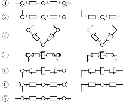
1.1 Manoeuvre steps for a six-body, five-joint architecture (left). Manoeuvre steps
for a four-body, three-joint architecture (right). . . 6
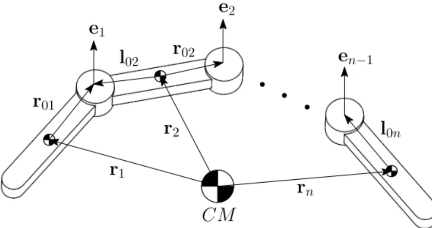
1.2 Geometric modelling of the robot. . . 9
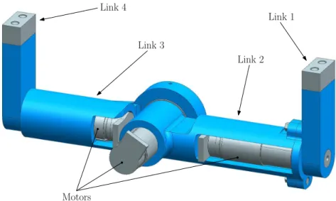
1.3 CAD model of the prototype. Parts in blue are made of 3D-printed ABS plastic.
Parts in grey are made of steel. . . 11
1.4 Dynamic simulation of the robot executing the manoeuvre. . . 11
1.5 Final orientation of the robot for different values of maximum joint displacement. 12
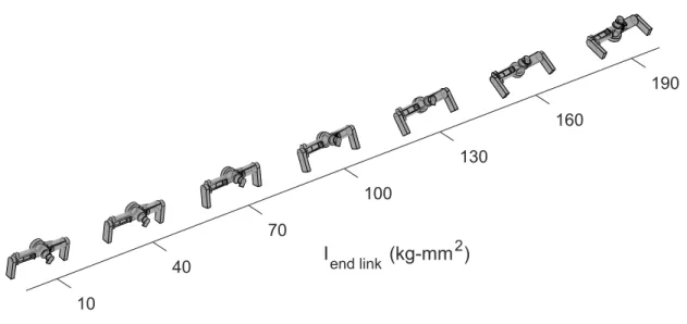
1.6 Final orientation of the robot for different values of moment of inertia of the end links. All simulations are for a maximum displacement of 270 degrees at
the distal joints and 120 degrees at the central joint. . . 13
1.7 Final orientation of the robot for different values of rotor inertia and gearbox ratio. All simulations are for a maximum displacement of 270 degrees at the
distal joints and 120 degrees at the central joint. . . 14
1.8 Still frames from the high speed footage . . . 16
1.9 Orientation of link 1 in space expressed with Euler angles α, β, γ following a
ZXZ convention. Theoretical and measured joint coordinates for the manoeuvre. 17
2.1 Description of manoeuvre A : Manoeuvre steps for a six-body, five-joint archi-tecture (left). Manoeuvre steps for a four-body, three-joint archiarchi-tecture (right).
Thinner line stubs show link orientation. . . 23
2.2 Description of manoeuvre B : Front view, manoeuvre steps for a four-body, joint architecture (left). Side view, manoeuvre steps for a four-body,
three-joint architecture (right). Thinner line stubs show link orientation. . . 24
2.3 Geometric modelling of the robot. . . 26
2.4 CAD model of the prototype. Parts in blue are made of 3D-printed ABS plastic.
Parts in grey are made of steel. . . 28
2.5 Dynamic simulation of the robot executing manoeuvre A. . . 29
2.6 Dynamic simulation of the robot executing manoeuvre B. . . 29
2.7 Final orientation of the robot after manoeuvre A for different values of
maxi-mum joint displacement. . . 29
2.8 Final orientation of the robot after manoeuvre A for different values of moment of inertia of the end links. All simulations are for a maximum displacement of
270 degrees at the distal joints and 120 degrees at the central joint. . . 31
2.9 Final orientation of the robot after manoeuvre A for different values of rotor inertia and gearbox ratio. All simulations are for a maximum displacement of
2.10 Final orientation of the robot after manoeuvre B for different values of maximum
joint displacement. . . 32
2.11 Physical prototype with VICON reflective markers. . . 33
2.12 Still frames from the high speed footage of the robot executing manoeuvre A. . 34
2.13 Orientation of link 1 in space expressed with Euler angles α, β, γ following a ZXZ convention for manoeuvre A. Theoretical and measured joint coordinates
for this manoeuvre.. . . 36
2.14 Orientation of link 1 in space expressed with Euler angles α, β, γ following a ZXZ convention for manoeuvre B. Theoretical and measured joint coordinates
for this manoeuvre.. . . 37
2.15 Orientation of the robot at the end of each manoeuvre of the sequence. . . 38
3.1 Schéma du processus de simulation. . . 45
3.2 Courbes couple-vitesse pour l’articulation centrale, pour la première étape de la manoeuvre. Coin supérieur gauche : Durée de 110 ms, moteur sous-utilisé. Coin supérieur droit : Durée de 100 ms, moteur sous-utilisé. Coin inférieur gauche : Durée de 90 ms, moteur utilisé efficacement. Coin inférieur droit : Durée de 80
ms, moteur sur-utilisé. . . 46
3.3 Détail du montage expérimental. À gauche : Détail du système de
déclenche-ment. À droite : Détail du panier servant à la réception du robot. . . 48
3.4 Diagramme de fonctionnement de la partie électronique du montage expérimental 48
3.5 Schéma de commande par couples pré-calculés. . . 49
Comme des nains sur les épaules de géants
Remerciements
Mes premiers remerciements vont à Clément Gosselin, qui en plus de m’avoir fait entrer dans le monde académique, m’y a aussi guidé par ses conseils éclairés. Merci de m’avoir donné ma chance il y a quelques années, de m’avoir fait confiance pendant mon cheminement et d’avoir toujours offert ton temps sans compter. J’ai adoré mon travail et cela t’est sans doute en grande partie attribuable.
Je tiens aussi à remercier Alexandre Campeau-Lecours et Philippe Cardou, qui m’ont égale-ment initié à la recherche. Votre passion pour votre vocation est contagieuse et ça a été un réel plaisir de vous côtoyer.
Je ne voudrais surtout pas passer sous silence la contribution de Thierry et Simon, deux véritables piliers du laboratoire. Toujours présents, autant dans l’ombre que sous les feux de la rampe, je vous assure que votre aide et votre apport ne passent pas inaperçus et je vous remercie mille fois pour ceux-ci.
À tous les membres du laboratoire que j’ai pu côtoyer, je dis merci pour les discussions enri-chissantes, l’aide théorique ou technique que vous avez pu offrir, mais surtout pour les rires. Finalement, je remercie mes parents, ma famille, mes amis et, bien entendu, ma partenaire de vie pour m’avoir offert un environnement sain et propice à l’épanouissement. Votre apport, bien que moins tangible, est aussi important que la somme de tous les autres.
Avant-propos
Le présent ouvrage est écrit suivant la forme d’un mémoire par articles. Les deux premiers chapitres sont donc des articles scientifiques rédigés en cours d’études, dans le cadre de la recherche entreprise pour l’obtention du grade.
Le premier article a été soumis le 13 septembre 2018 à l’édition 2019 de l’International Confe-rence on Robotics and Automation (ICRA). Cette conféConfe-rence annuelle se déroule sous l’égide de l’Institute of Electrical and Electronics Engineers (IEEE). Vu le caractère international de la conférence, la langue de rédaction est l’anglais. Les travaux de recherche nécessaires à la préparation de cet article ont été réalisés par l’étudiant, sous la supervision du directeur de recherche et seul co-auteur Clément Gosselin. En ce sens, l’article a été rédigé par l’étu-diant, puis revu par le directeur de recherche. L’étudiant est donc le premier auteur pour cette publication.
Le deuxième article est une version finale prête à la soumission à la revue scientifique Tran-sactions on Robotics de l’IEEE. Le caractère international de la revue impose l’anglais comme langue de rédaction. La préparation de cet ouvrage a suivi un processus de publication que l’IEEE appelle évolutif, c’est-à-dire que l’article présente la suite des travaux soumis précé-demment. Il reprend donc une partie du contenu de l’article précédent pour développer de nouvelles contributions, telles qu’énoncées ci-bas :
1. Une deuxième manoeuvre de réorientation est présentée. Cette manoeuvre permet au robot d’accomplir des rotations nettes autour d’un axe différent, tel que démontré en simulation.
2. Des essais expérimentaux supplémentaires établissent la validité de la simulation dyna-mique de cette deuxième manoeuvre.
3. Il est démontré que n’importe quelle orientation dans l’espace 3D peut être atteinte en ajoutant cette deuxième manoeuvre.
4. Une simulation dynamique supplémentaire appuie cette affirmation en montrant que le robot peut modifier son orientation de façon arbitraire en enchaînant les deux ma-noeuvres de façon alternée.
la supervision du directeur. L’étudiant a donc rédigé l’article à titre de premier auteur, avec l’appui du directeur et seul co-auteur Clément Gosselin pour la révision.
Un chapitre additionnel expliquant la démarche expérimentale est inclus à la suite des deux articles. Cet ajout a été fait suivant les recommandations de la direction de programme, puisque le format compact des publications scientifiques tend à évacuer cette information. Ce chapitre est donc écrit dans l’optique de détailler les processus de simulation et de validation expérimentale qui ont mené aux conclusions finales.
Introduction
Que ce soit en repoussant les frontières de l’inconnu par l’exploration spatiale, en reproduisant des gestes auparavant réservés au monde animal, ou en rivalisant avec la motricité de l’être humain, la robotique, telle que nous la connaissons aujourd’hui, a fait des bonds de géant depuis sa démocratisation au milieu du 20esiècle. En effet, bien que l’idée de sortir les robots du cadre manufacturier se soit imposée graduellement, elle est maintenant la source d’initiatives de recherche qui brouillent continuellement les limites du possible. En l’occurrence, un domaine de recherche découlant du décloisonnement des applications robotiques et qui établit un pont entre l’exploitation de l’espace et le biomimétisme est celui de la réorientation inertielle. Kane et Scher (Kane and Scher, 1970) sont souvent cités à titre de précurseurs dans ce do-maine, ayant établi un cadre mathématique permettant d’expliquer la réorientation du chat en chute libre. Le réflexe de redressement du chat, bien que d’apparence anodine, est néan-moins un exemple parfait d’un phénomène qui est resté une énigme pour la science jusqu’au milieu du siècle dernier. À juste titre, il paraît contre-intuitif qu’avec un moment cinétique nul et en l’absence de force externe, un simple corps articulé en chute libre puisse modifier son orientation dans l’espace. Pourtant, en y prêtant attention, on remarque que ce phénomène est présent partout autour de nous. D’autres animaux, tels que les lézards (Jusufi et al.,2010) tirent profit de cette stratégie. Sans elle, les plongeurs acrobatiques, gymnastes et trampo-linistes amateurs comme professionnels seraient totalement démunis (Frohlich, 1980). Enfin, qui ne s’est jamais retrouvé à lever instinctivement les bras dans les airs pour se redresser au moment d’une chute sur la glace ?
Il s’avère que ce phénomène appartient à une classe de problèmes traitant des systèmes non holonomes. Conséquemment, l’état d’un tel système dépend de la trajectoire que suivent les paramètres qui le décrivent (Shapere, 1988). Cet état peut par ailleurs être modifié même si les paramètres du système reviennent à leur valeur initiale suivant une trajectoire fermée. Concrètement, ceci signifie qu’à l’instar d’un chat ou d’un trampoliniste, un robot peut se réorienter en suivant une séquence de mouvements qui ramène toutes ses articulations à leur position initiale.
Ce constat permet de dégager deux grands champs d’application où une telle capacité pourrait être bénéfique ou même essentielle. D’une part, un engin spatial équipé, par exemple, d’un
manipulateur robotique, pourrait modifier son orientation sans avoir recours à des propulseurs ou à des systèmes supplémentaires tels que des roues d’inertie. Dans un contexte où les débris et les satellites défectueux en orbite autour de la Terre posent un risque de plus en plus sérieux pour l’avenir de l’activité humaine dans l’espace, on peut s’attendre à ce que des satellites d’entretien, équipés de bras robotiques, deviennent une réalité dans un futur rapproché ( Flores-Abad et al., 2014). D’autre part, la réorientation en chute libre peut s’avérer pratique pour les robots terrestres ayant la capacité de faire des sauts ou qui sont potentiellement sujets à des chutes. Dans ce contexte, la possibilité de modifier l’orientation du robot, de manière à amoindrir le potentiel de dommage causé par un impact avec le sol devient en effet très intéressante.
Objectifs du mémoire
L’objectif des travaux de recherche présentés dans ce mémoire est donc d’étudier la problé-matique de la réorientation des robots articulés en chute libre, soumis à un moment cinétique nul. Plus précisément, les objectifs sont de :
1. Développer une stratégie de réorientation réalisable dans l’espace tridimensionnel, per-mettant d’atteindre une orientation finale arbitraire.
2. Simuler le comportement dynamique du robot avec l’aide d’outils numériques afin de valider la stratégie proposée.
3. Concevoir un montage physique et une méthode permettant la validation expérimentale des résultats obtenus en simulation.
Structure du mémoire
Le premier chapitre de ce mémoire présente l’étude d’une première manoeuvre de réorientation analogue au réflexe de redressement du chat. L’effet de l’amplitude des mouvements articu-laires sur le comportement de la manoeuvre, ainsi que l’impact de paramètres de conception importants sont explorés à l’aide de simulations dynamiques. Enfin, les résultats des simula-tions sont validés expérimentalement.
Le second chapitre reprend une partie du contenu du premier chapitre pour présenter une deuxième manoeuvre de réorientation. Cette dernière est réalisable par le même robot sans nécessiter de modifications. Le comportement dynamique de cette deuxième manoeuvre est également étudié en simulation. Ensuite, une validation expérimentale appuie les résultats obtenus et permet de comparer les deux manoeuvres. Enfin, dans la dernière section du chapitre est discutée la possibilité d’atteindre une orientation arbitraire en utilisant seulement ces deux manoeuvres.
Bibliographie
A. Flores-Abad, O. Ma, K. Pham, and S. Ulrich. A review of space robotics technologies for on-orbit servicing. Progress in Aerospace Sciences, 68 :1–26, jul 2014.
C. Frohlich. The Physics of Somersaulting and Twisting. Scientific American, 242 :154–165, 1980.
A. Jusufi, D. T. Kawano, T. Libby, and R. J. Full. Righting and turning in mid-air using appendage inertia : Reptile tails, analytical models and bio-inspired robots. Bioinspir. Biomim. 5 045001 Bioinsp. Biomim, 5 :45001–12, 2010.
T. Kane and M. Scher. Human self-rotation by means of limb movements. Journal of Biome-chanics, 3(1) :39–49, jan 1970.
A. D. Shapere. Gauge mechanics of deformable bodies. PhD thesis, University of California, Santa Barbara, 1988.
Chapitre 1
Design and Experimental Validation of
a Manoeuvre Inspired from the Cat
Righting Reflex for the Reorientation
of a Free Falling Robot
1.1
Résumé
Cet article présente une manoeuvre permettant à un robot d’exécuter des rotations selon son axe longitudinal par le biais de trajectoires fermées dans l’espace articulaire. Il est montré par simulation dynamique que l’amplitude de la rotation nette dépend de l’amplitude du déplacement angulaire des articulations. Avec des limites articulaires réalistes, le robot, qui ne possède que des articulations rotoïdes, est en mesure d’exécuter une rotation de 180 degrés similaire au réflexe de redressement du chat. Les résultats obtenus en simulation sont validés expérimentalement avec un prototype et un système de capture de mouvements VICON.
1.2
Abstract
This paper presents a manoeuvre allowing an articulated robot in free fall to rotate along its longitudinal axis using closed-loop paths in the joint space. It is shown through dynamics simulations that the magnitude of the net rotation is dependent upon the amplitude of angular displacement. With realistic joint limitations, the robot, which incorporates rotary actuators only, can perform a 180-degree reorientation similar to the cat righting reflex. The simulation results are experimentally validated with a prototype and a VICON motion tracking system.
1.3
Introduction
The elusive phenomenon of the self-righting cat falls under the category of problems gover-ned by the law of constant angular momentum. Indeed, with nothing to push against, the cat manages to modify its orientation while free falling, by using the movements of its spine and limbs exclusively. Kane and Scher (Kane and Scher,1969) were among the firsts to prove that a simplified mathematical model-cat could accomplish a 180 degree flip by executing a specific sequence of movements of the spine. Naturally, several research initiatives in the field of robotics sprouted from the study of this particular phenomenon, and the more general case of reorienting a mechanical system of articulated bodies (Shapere and Wilczek, 1989). As a matter of fact, it is nowadays possible to consider applications where having this abi-lity is not only relevant but essential for a robot. Notably, posture control while falling to mitigate impact for articulated robots was investigated in (Yang et al.,2011;Bingham et al.,
2014). Lizard-like self-righting through the use of a tail was studied with simplified systems composed of two bodies in (Jusufi et al., 2010; Chang-Siu et al., 2011; Zhao et al., 2015). However, most of the theoretical research in this area is centred on space systems and satellite control. The ability to control the orientation of multi-body space systems using internal mo-vements could notably reduce the amount of propellant needed and save weight by removing the need for auxiliary systems such as reaction wheels or magnetic torquers. Several modelling methods have been proposed for free-floating space manipulators, like the virtual manipu-lator approach (Dubowsky and Papadopoulos, 1993) and the generalized Jacobian (Yoshida and Umetani, 1993). Nonlinear control models based on Lie brackets and controllability for this case of nonholonomic problem have also been investigated in depth (Reyhanoglu and McClamroch,1992;Kolmanovsky et al.,1995;Rui et al.,1997,2000).
This article proposes a manoeuvre for reorienting an articulated robot under zero angular momentum in a weightless environment. Much like the cat motion itself, the method relies on closed paths (loops) in the joint space to produce a net change in orientation. With reasonable joint limits, the manoeuvre allows for a 180 degree net rotation about the longitudinal axis of the robot. The manoeuvre can also be repeated any number of times with different movement amplitudes to achieve a desired rotation.
While much theoretical work has been done on orienting multi-body systems in free fall, to the best of the knowledge of the authors, few research papers provide experimental validation of the results in 3D space. This may be due in part to the challenge that reproducing weightlessness conditions represents. In a previous paper, a planar mechanism was proposed (Bettez-Bouchard and Gosselin, 2016) for validation purposes. However, due to the planar architecture of the robot, the manoeuvres required the robot to collide with itself. In practice, manipulators have joint limits to prevent self-collision. One example of an experimentally validated robot capable of righting itself in free fall while incorporating joint limitations is presented in (Mather and Yim, 2009). However, the method that is used requires that an actuated Hooke joint be
positioned centrally on the robot, which limits its practicality. The present paper aims at addressing the above considerations.
This paper is structured as follows. The proposed reorientation manoeuvre is first described in Section 1.4. Then, the mathematical model, which is based on the conservation of angular momentum, is introduced in Section1.5. Section1.6presents the design of the prototype of an articulated robot on which the proposed manoeuvre is implemented. Simulation results obtai-ned with a dynamic simulation program are then presented in Section 1.7, where the effects of some of the design parameters on the reorientation are studied and discussed. Section 1.8
presents the experimental validation of the manoeuvre using the physical 3-dof articulated prototype. Finally, conclusions are drawn in Section 1.9.
1.4
Reorientation Manoeuvre
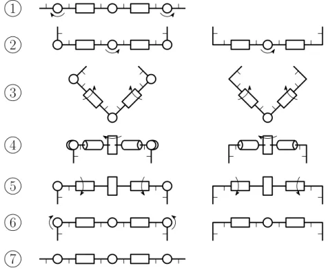
The proposed manoeuvre can be decomposed in six steps, as shown in Figure1.1. Transposing this method to the falling cat would imply that the animal twists its body along the spine axis, as opposed to Kane and Scher’s "no-twist" model. There are diverging opinions on whether the cat effectively does so (Frohlich,1979). However, the manoeuvre is comparable to a "swivel-hips" that trampolinists execute to rotate their body 180 degrees (Frohlich,1979).
1
2
3
4
5
6
7
Figure 1.1 – Manoeuvre steps for a six-body, five-joint architecture (left). Manoeuvre steps for a four-body, three-joint architecture (right).
rotary actuators. However, the system can be reduced to four bodies and three rotary actuators for simplicity, without notable loss of performance. We can discard steps 1 and 6 and use an "L" shape for the first and last links of the chain, without actuators 1 and 5, as shown in Figure1.1. This simplifies the experimental process by reducing the number of control inputs and allowing more time for the most important parts of the sequence before the robot touches the ground.
The manoeuvre works by changing the moment of inertia of certain parts of the system between each actuation of the joints. For instance, at step 3, when actuating joint 2 of the six-body system, the moment of inertia (with respect to the joint axis) of the combined bodies to the right of the joint is much larger than the moment of inertia of the bodies to the left. Thus, qualitatively, the left segment will be subject to a large rotation, while the right segment will experience little rotation. By contrast, at step 5, the relative moments of inertia of the left and right sides are similar, therefore both sides will rotate by a similar amount. This way, the relative angle between each link always returns to its original value at the end of the manoeuvre, effectively meaning that the robot goes back to its starting configuration in the joint space.
This type of manoeuvre, when executed in free-fall, has the interesting characteristic of being time-independent. In other words, the speed at which the manoeuvre is executed has no impact on the final state of the system : only the geometric path matters. A mathematical proof of this property can be found in (Shapere,1988). Thus, we can use a representation of the trajectories in joint space without losing significant information, and use this to our advantage for easier parametrization of the trajectories. The proposed manoeuvre for the simplified three-joint architecture is then represented as a closed path in the joint-space.
1.5
Mathematical Background
In order to provide a better understanding of the physics at play during the reorientation, the dynamic model of a free floating serial robot with n links and j revolute joints (j = n − 1) is derived in this section. The formulation presented here was proposed in (Bettez-Bouchard and Gosselin,2016) as an adaptation of (Dubowsky and Papadopoulos,1993).
Free floating manipulators differ from their earth-based counterparts in that the position and orientation of each link depend on the position and orientation of every other link in the chain (Wittenburg, 2007). As a consequence of the conservation of momentum, the dynamic behaviour of a free floating multibody system can be expressed with respect to its global centre of mass (CM ), as shown in Figure1.2. Since the position of the CM is constant in a reference frame R0 moving with the robot, the position ri and velocity vi of the centre of mass (CMi) of link i (i = 1, . . . , n) is related to that of the other bodies as follows
n X i=1 miri = 0 (1.1) and n X i=1 mivi= 0 (1.2)
where mi is the mass of link i. Moreover, the conservation of the angular momentum leads to dh dt = 0 (1.3) with h = n X i=1 (Iiωi+ miri× vi) (1.4)
where h is the angular momentum, Iiis the inertia tensor of link i and ωiis its angular velocity. As previously stated, it is assumed that the robot is initially at rest (ωi = vi= 0, i = 1, . . . , n) and that no external torque is applied to it during the reorientation, thus h is set to 0. To compute (1.4), each term must be expressed in the same reference frame, in this case R0. The rotation from reference frame i − 1 to reference frame i can be expressed with matrix Qi using an axis angle representation. With θi the rotation angle about unit vector ei (expressed in its local reference frame) corresponding to the axis of the ith revolute joint, this yields
Qi = ei−1eTi−1+ ci(1 − ei−1eTi−1) + si1 × ei−1 i = 2, . . . , n (1.5) with 1 × ei = 0 −ei3 ei2 ei3 0 −ei1 −ei2 ei1 0 (1.6)
and where ci and si respectively stand for cos θi and sin θi, while 1 stands for the 3 × 3 identity matrix. Matrix Q1 corresponds to the rotation from the inertial reference frame to link 1. The representation in R0 is then obtained by pre-multiplying by the product of rotation matrices Q1 to Qi in the case of a vector, and also by post-multiplying by the transpose of these rotation matrices in the case of a tensor. For instance, ei and Ii, which are expressed in R0, are obtained as ei = ( i Y 1 Qi) ei (1.7) Ii= ( i Y 1 Qi) Ii( 1 Y i QTi ) (1.8)
where an underscore implies that the vector or tensor is expressed in its local reference frame. Next, ri, vi and ωi must be explicited. The derivation of these terms is based on the concept of barycentre (Wittenburg, 2007), adapted to free floating serial manipulators in ( Bettez-Bouchard and Gosselin,2016;Dubowsky and Papadopoulos,1993). For each link, two constant
construction vectors are defined, namely r0iand l0i, as shown in Figure1.2. Vector r0iconnects CMi to joint i, while vector l0iconnects CMi to joint i − 1.
e
1e
2e
n−1CM
r
01l
02r
02l
0nr
1r
2r
nFigure 1.2 – Geometric modelling of the robot.
Combining these vectors with the mass of the links yields the position of the barycentre c0i, which is given by
c0i= l0iµi+ r0i(1 − µi+1) (1.9) with µi the mass distribution in the robot, given by
µi = 0 i = 1 i−1 P k=1 mk M i = 2, . . . , n 1 i = n + 1 (1.10)
where M is the total mass of the robot. Vector c0i can equivalently be found by adding a point mass M µi to joint i − 1 and M (1 − µi+1) to joint i, which defines an augmented link (Wittenburg,2007). The barycentre then becomes the centre of mass of this augmented link (Dubowsky and Papadopoulos, 1993). New augmented construction vectors can be defined with respect to this centre of mass, as
c∗0i= −c0i (1.11)
r∗0i= r0i− c0i (1.12)
l∗0i= l0i− c0i. (1.13)
Similarly to vector ri, these vectors are fully specified by the configuration of the robot, which depends on the joint angles collected in vector θ. It can be shown that ri can be expressed in terms of the barycentric vectors, which yields
ri = n X k=1
with bki defined using the following rule bki = l∗0k k > i c∗0k k = i r∗0k k < i . (1.15)
Vector ωican be expressed in R0 by adding the angular velocity vector imparted by each joint with the angular velocity ω1 of the first link, which yields
ωi =
ω1 i = 1
ωi−1+ ei−1θ˙i−1 i = 2, . . . , n.
(1.16)
Considering that vector bki is constant in the reference frame moving with angular velocity ωi, vi is obtained as vi= n X k=1 ωk× bki i = 1, . . . , n. (1.17) Equation (1.17) can be rearranged with the help of (1.16), yielding
vi = ω1× ri+ Ciθ˙ (1.18)
where Ci is a matrix of dimension 3 × j which is a function of the construction parameters of the robot.
Equations (1.14), (1.16) and (1.18) can now be substituted into (1.4) — where h is set to zero — to form a system of equations that depends only on the unknowns ω1 and ˙θ. The double vector product obtained in the process can be rearranged as
miri× (ω1× ri) = mi((riTri)1 − rirTi )ω1. (1.19) Finally, collecting the terms in ω1 on one side and the terms in ˙θ on the other side, a linear system of equations that relates the angular velocity of the first body and the joint velocity vector of the robot is obtained as
Aω1 = B ˙θ (1.20)
where A is a 3×3 matrix and B is a matrix of dimension 3×j, which both depend on the mass of the links, the geometric parameters and the configuration of the robot. This formulation of the dynamic model is general and is applicable to any spatial or planar serial free-floating robot.
1.6
Prototype Design
Based on the simplified three-joint architecture presented in Section 1.4, an experimental prototype was designed and built. A CAD model of the prototype is shown in Fig 1.3. The
robot was designed without any on-board electronics except for the motors themselves. One drawback of this design is that it requires an experimental setup where cables must run between each motor and an external controller for power and encoder signals. The measures that were taken to mitigate the influence of the hanging cables are addressed in more details in Section1.8.
The total mass of the robot is approximately 0.3 kg. Machined steel inserts were added to the ends of links 1 and 4 in order to position their centre of mass in a way that favours the reorientation. Links 2 and 3 are hollow, allowing motors to be mounted inside them. The motors are 4.5 Watt brushed DC RE-max 17 with 24 :1 gearheads and 512 counts per turn encoders. Link 4 Link 1 Link 2 Link 3 Motors
Figure 1.3 – CAD model of the prototype. Parts in blue are made of 3D-printed ABS plastic. Parts in grey are made of steel.
1.7
Simulation
Using the CAD model, dynamic simulations were performed using Siemens NX to study the effects of various parameters on the dynamics of the robot in zero-gravity. Figure 1.4 shows the progression of the reorientation manoeuvre simulated with the CAD model.
1.7.1 Trajectory in the joint space
The influence of the amplitudes of the movements on the net change in orientation was first investigated. In the joint space, this is equivalent to varying the dimensions of the rectangle loop that represents the trajectory. The final orientation as a function of maximum joint displacement is presented in Figure 1.5.
1,max , 3,max (deg)
270 202.5 120 135 2,max (deg) 90 60 67.5 30 0 0
Figure 1.5 – Final orientation of the robot for different values of maximum joint displacement.
As it can be observed, the axis describing the net rotation induced by the manoeuvre varies very little with respect to maximum joint displacement. This means that the manoeuvre produces a rotation almost purely about the roll axis of the robot and that undesirable motions around other axes are almost nonexistent. In addition, the net rotation itself increases smoothly with respect to the maximum movement amplitude of both joints. Therefore, small internal movements of the robot produce a small reorientation while large internal movements produce a large reorientation, meaning that the manoeuvre behaves predictably. Moreover, with a reasonable displacement limit of 270 degrees for the distal joints and 120 degrees for the centre joint, a net rotation of approximately 180 degrees is predicted by the simulation. For a cat-like reorientation, a half-turn is the worst case scenario, since a rotation of more than 180 degrees is equivalent to a smaller rotation in the opposite direction. Practically, rotating in the opposite direction can be done by reversing the direction of rotation of joints 1 and 3.
1.7.2 Moment of inertia of the end links
The effect of different inertial parameters on the manoeuvre was also studied. The starting point of this analysis is the realization that drastically increasing the moments of inertia of
links 2 and 3 results in no reorientation. Indeed, having bodies 1 and 4 linked to a very high inertia would be comparable to fixing the stators of motors 1 and 3 in space. For this reason, the study was focused on the moment of inertia of links 1 and 4 about joint axes 1 and 3, respectively. Figure 1.6 shows the resulting net rotation for different values of moment of inertia, with the same prescribed joint trajectories for each simulation. For this robot, it can be observed that a moment of inertia of up to approximately 100 kg-mm2 contributes to the desired reorientation, that is, a net rotation of 180 degrees. Increasing the inertia past this point has adverse effects on the manoeuvre, notably inducing a progressively greater amount of off-axis rotation and reducing the net amount of rotation about the principal axis of the robot. Moreover, a greater moment of inertia would require higher torques at joints 1 and 3 in order to accomplish the manoeuvre.
190 I end link (kg-mm 2 ) 160 130 100 70 40 10
Figure 1.6 – Final orientation of the robot for different values of moment of inertia of the end links. All simulations are for a maximum displacement of 270 degrees at the distal joints and 120 degrees at the central joint.
1.7.3 Motor gear ratio and rotor inertia
With weightless robots, extra care must be taken in the selection of the motors for joint actuation. Indeed, the motors can significantly influence the dynamic behaviour of the robot in free fall, depending on their properties. For instance, a gearmotor with a very high reduction ratio might offer more torque, but its fast spinning rotor may disturb the manoeuvre. To better characterize the influence of the gear ratio and the rotor inertia on the manoeuvre, simulations were performed with different values of these parameters. The results are shown in Figure1.7. It can be observed that for this specific manoeuvre and geometric configuration, increasing
1/87.5 I rotor /Ilink 1/175 48:1 1/350 Gearbox ratio 36:1 24:1 1/700 12:1 1/1400 1:1
Figure 1.7 – Final orientation of the robot for different values of rotor inertia and gearbox ratio. All simulations are for a maximum displacement of 270 degrees at the distal joints and 120 degrees at the central joint.
both the moment of inertia of the rotor and the reduction ratio results in a greater net reorientation. In other words, a smaller maximum displacement at the joints would be sufficient to achieve a net rotation of 180 degrees about the roll axis of the robot. Still, there is a trade-off between performance, form factor, weight and availability of parts, which explains the choice of a 24 :1 ratio and rotor inertia of 0.1 kg-mm2 for the current robot.
1.8
Experimental Validation
In order to validate the simulation results, the robotic prototype presented in Section 1.6was built and an experimental set-up was designed. The drop post shown in the background in Figure 1.8 allows 2 metres of free fall, which is equivalent to approximately 0.6 second of weightlessness. The robot lands in a flexible basket mounted on a damped spring at the end of the drop. In order to limit the influence of initial conditions as much as possible, the release mechanism is a set of two electromagnets. The robot is completely still before release and the manoeuvre only begins 0.02 second after the electrical signal is sent to the electromagnets, to ensure that the robot is effectively released and to prevent any contact with the magnets during the manoeuvre. As mentioned in Section 1.6, the robot has no on-board electronics. To mitigate the influence of the cables connecting the robot to the controller, the thinnest possible extra flexible silicon insulated wires were used. In addition, a third electromagnet releases the wires simultaneously with the robot. This prevents the wires from pulling on the robot at the
instant of release and inducing angular momentum. When the fall is initiated, both the robot and the wires are weightless, thus the manoeuvre is only affected by the relatively small inertia of the wires.
For practical reasons, the drop height is limited. Thus, it is necessary to verify that the motors have enough power to execute the manoeuvre in the allowed time. To this end, the torque and speed values at each time step are extracted from the dynamic simulations of the manoeuvre and compared against the torque-speed limiting curve of the motors provided by the manufacturer. The allotted time for each step of the manoeuvre is then iteratively adjusted until a minimum-time trajectory is obtained.
It is important to note that the only control input to this robot is the relative angle between each pair of consecutive links. This means that while joints 1, 2 and 3 follow a prescribed trajectory through the use of a PID position control, the orientation of the robot in 3D space is only observed.
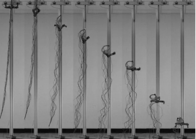
For qualitative analysis, the robot was filmed with a high speed camera at 800 frames per second. Figure1.8presents still frames from a typical test drop. From these images, it can be observed that the orientation of the robot follows what was predicted by the simulations. The prototype accomplishes a half-turn net rotation at the end of the prescribed sequence of joint movements, even with the wires linked to a fixed controller.
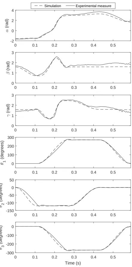
For quantitative validation of the observations, the orientation of the first link of the robot was tracked using a VICON motion capture system at a sampling rate of 300 Hz. The markers that are required for tracking have a negligible mass and were positioned on the body so as not to hinder the manoeuvre. Figure 1.9shows the progression of the orientation with a ZXZ Euler angle representation. It can be clearly observed that the second and third angles return to their initial value at the end of the fall, while the first angle increases by 3.35 rad. With this convention, the first angle corresponds to the roll axis of the robot. This rotation of just over 180 degrees is what was predicted by the simulation. Figure 1.9 also shows that while joint coordinates did not exactly follow the prescribed curves, θ1 and θ3 stayed synchronised and each articulation reached the desired angular value at the prescribed time without any overlap between θ2 and θ1or θ3. Thus, the data show that the reorientation can be considered successful. Moreover, the experimentally measured orientation of link 1 closely follows the simulation results, with a RMS error of 0.24 rad (13.8o) on the first angle, 0.21 rad (12o) on the second angle and 0.14 rad (8o) on the third angle.
1.9
Conclusion
A reorientation manoeuvre was elaborated and tested with a robotic prototype. The cat-like movement sequence achieved a net rotation of a half-turn almost purely about the longitudinal
Figure 1.8 – Still frames from the high speed footage
axis of the robot. Furthermore, the manoeuvre proved stable with respect to maximum joint displacement. That is, lowering the limits on either the central or distal joints only resulted in a smaller net rotation about the same axis. Thus, a large rotation about a single axis can be decomposed as a repetition of smaller rotations : the same manoeuvre can be repeated any number of times to achieve an arbitrary rotation about a single axis. Admittedly, this may be impossible for terrestrial robots in free fall, since time is limited by the height of the fall. However, space robots benefit from having a virtually infinite amount of time to accomplish a sequence of manoeuvres. In that case, the movements can be made arbitrarily slow and the joint limits decreased to reduce the required torques at the joints and improve the safety margin for self-collision.
It is also worth restating that the presented proof of concept prototype was specifically designed with the intent of validating the proposed manoeuvre. Still, the manoeuvre lends itself to a typical 7-DoF shoulder-elbow-wrist serial manipulator architecture. This type of serial robot is frequent in space applications and notable examples include Canadarm2, the European Robotic Arm and the DARPA FREND arm (Flores-Abad et al.,2014).
0 0.1 0.2 0.3 0.4 0.5 -2 0 2 4 (rad) 0 0.1 0.2 0.3 0.4 0.5 0 1 2 3 (rad) 0 0.1 0.2 0.3 0.4 0.5 0 1 2 3 (rad) 0 0.1 0.2 0.3 0.4 0.5 0 100 200 300 1 (degrees) 0 0.1 0.2 0.3 0.4 0.5 -150 -100 -50 0 50 2 (degrees) 0 0.1 0.2 0.3 0.4 0.5 Time (s) -300 -200 -100 0 3 (degrees)
Simulation Experimental measure
Figure 1.9 – Orientation of link 1 in space expressed with Euler angles α, β, γ following a ZXZ convention. Theoretical and measured joint coordinates for the manoeuvre.
of angular momentum. If the robot already has angular momentum, moving its links can result in off-axis spins that are more complex to predict, such as when a diver performs a twisting somersault (Frohlich,1979). Another limitation is the fact that while the motors in the joints of the robot are controlled in closed-loop, its orientation in 3D space is only controlled in open-loop. As previously stated, there are no on-board electronics, hence no sensors for feedback and reaction to disturbances. Consequently, future work will consist in developing a control method to dynamically adapt the basic joint trajectories for improved accuracy and stability on the orientation of the robot.
1.10
Bibliographie
J.-A. Bettez-Bouchard and C. Gosselin. Development and experimental validation of a reo-rientation algorithm for a free-floating serial manipulator. In 2016 IEEE International Conference on Robotics and Automation (ICRA), pages 2733–2738. IEEE, may 2016. J. T. Bingham, J. Lee, R. N. Haksar, J. Ueda, and C. K. Liu. Orienting in mid-air through
configuration changes to achieve a rolling landing for reducing impact after a fall. In 2014 IEEE/RSJ International Conference on Intelligent Robots and Systems, pages 3610–3617. IEEE, sep 2014.
E. Chang-Siu, T. Libby, M. Tomizuka, and R. J. Full. A lizard-inspired active tail enables rapid maneuvers and dynamic stabilization in a terrestrial robot. In 2011 IEEE/RSJ International Conference on Intelligent Robots and Systems, pages 1887–1894. IEEE, sep 2011.
S. Dubowsky and E. Papadopoulos. The kinematics, dynamics, and control of free-flying and free-floating space robotic systems. IEEE Transactions on Robotics and Automation, 9(5) : 531–543, 1993.
A. Flores-Abad, O. Ma, K. Pham, and S. Ulrich. A review of space robotics technologies for on-orbit servicing. Progress in Aerospace Sciences, 68 :1–26, jul 2014.
C. Frohlich. Do springboard divers violate angular momentum conservation ? American Jour-nal of Physics, 47(7) :583–592, jul 1979.
A. Jusufi, D. T. Kawano, T. Libby, and R. J. Full. Righting and turning in mid-air using appendage inertia : Reptile tails, analytical models and bio-inspired robots. Bioinspir. Biomim. 5 045001 Bioinsp. Biomim, 5 :45001–12, 2010.
T. R. Kane and M. P. Scher. A dynamical explanation of the falling cat phenomenon. Inter-national Journal of Solids and Structures, 5(7) :663–670, 1969.
I. Kolmanovsky, N. H. McClamroch, and V. T. Coppola. New results on control of multibody systems which conserve angular momentum. Journal of Dynamical and Control Systems, 1 (4) :447–462, oct 1995.
T. W. Mather and M. Yim. Modular configuration design for a controlled fall. In 2009 IEEE/RSJ International Conference on Intelligent Robots and Systems, pages 5905–5910. IEEE, oct 2009.
M. Reyhanoglu and N. H. McClamroch. Planar reorientation maneuvers of space multibody systems using internal controls. Journal of Guidance, Control, and Dynamics, 15(6) :1475– 1480, nov 1992.
C. Rui, I. Kolmanovsky, and N. McClamroch. Control problems for a multibody spacecraft via shape changes : constant nonzero angular momentum. In Proceedings of the 1997 American Control Conference (Cat. No.97CH36041), pages 1904–1908 vol.3. IEEE, 1997.
C. Rui, I. Kolmanovsky, and N. McClamroch. Nonlinear attitude and shape control of space-craft with articulated appendages and reaction wheels. IEEE Transactions on Automatic Control, 45(8) :1455–1469, 2000.
A. Shapere and F. Wilczek. Gauge kinematics of deformable bodies. American Journal of Physics, 57(6) :514–518, jun 1989.
A. D. Shapere. Gauge mechanics of deformable bodies. PhD thesis, University of California, Santa Barbara, 1988.
J. Wittenburg. Dynamics of multibody systems. Springer Science & Business Media, 2007. E. C.-Y. Yang, P. C.-P. Chao, and C.-K. Sung. Optimal Control of an Under-Actuated System
for Landing With Desired Postures. IEEE Transactions on Control Systems Technology, 19 (2) :248–255, mar 2011.
K. Yoshida and Y. Umetani. Control of Space Manipulators with Generalized Jacobian Matrix. pages 165–204. Springer, Boston, MA, 1993.
J. Zhao, T. Zhao, N. Xi, M. W. Mutka, and L. Xiao. MSU Tailbot : Controlling Aerial Ma-neuver of a Miniature-Tailed Jumping Robot. IEEE/ASME Transactions on Mechatronics, 20(6) :2903–2914, dec 2015.
Chapitre 2
Reorientation of a free-floating robot
using closed-loop paths in the joint
space
2.1
Résumé
Cet article présente deux manoeuvres distinctes permettant à un robot articulé en chute libre de changer son orientation par le biais de trajectoires fermées dans l’espace articulaire. Il est montré par simulation dynamique que l’amplitude de la rotation nette dépend de l’amplitude du déplacement angulaire des articulations. Avec des limites articulaires réalistes, le robot, qui ne possède que des articulations rotoïdes, est en mesure d’exécuter une rotation de 180 degrés similaire au réflexe de redressement du chat. La seconde manoeuvre permet au robot d’accomplir des rotations de moindre amplitude selon un axe différent. Les résultats obtenus en simulation sont validés expérimentalement avec un prototype et un système de capture de mouvements VICON. Enfin, il est montré que le robot peut atteindre n’importe quelle orientation en répétant ou en alternant les manoeuvres.
2.2
Abstract
This paper presents two distinct manoeuvres allowing an articulated robot in free fall to change its orientation using closed-loop paths in the joint space. It is shown through dynamics simulations that the magnitude of the net rotation is dependent upon the amplitude of the angular displacement of the joints. With realistic joint limitations, the robot, which includes rotary actuators only, can perform a 180-degree reorientation about its longitudinal axis, similar to the cat righting reflex. The second manoeuvre allows the robot to accomplish rotations of smaller magnitude about a different axis. A physical prototype and a VICON motion tracking system are used to experimentally validate the simulation results. Finally, it
is shown that the robot can reach any orientation by repeating or alternating the manoeuvres.
2.3
Introduction
The elusive phenomenon of the self-righting cat falls under the category of problems governed by the law of constant angular momentum. Indeed, with nothing to push against, the cat manages to modify its orientation while free falling, by using the movements of its spine and limbs exclusively. Kane and Scher (Kane and Scher, 1969) were among the firsts to prove that a simplified mathematical model-cat could accomplish a 180 degree flip by executing a specific sequence of movements of the spine. Naturally, several research initiatives in the field of robotics sprouted from the study of this particular phenomenon, and the more general case of reorienting a mechanical system of articulated bodies (Shapere and Wilczek, 1989). As a matter of fact, it is nowadays possible to consider applications where having this ability is not only relevant but essential for a robot. Notably, posture control while falling to mitigate impact for articulated robots was investigated in (Yang et al.,2011;Bingham et al.,2014). Lizard-like self-righting through the use of a tail was studied with simplified systems composed of two bodies in (Jusufi et al., 2010; Chang-Siu et al., 2011; Zhao et al., 2015). Another problem which is closely related to the falling cat phenomenon is the reorientation of humans in free fall. Gymnasts and divers are frequently confronted to this situation as they perform twists and flips in mid-air with zero initial angular momentum (Frohlich,1979,1980). Moreover, with the advent of human spaceflight, these manoeuvres were studied extensively (Kulwicki et al.,
1962; Smith and Kane,1967; Kane and Scher,1970; Stirling, 2008) in order to devise ways for astronauts to change their orientation in weightlessness. However, most of the theoretical research in this area is centred on space systems and satellite control. The ability to control the orientation of multi-body space systems using internal movements could notably reduce the amount of propellant needed and save weight by removing the need for auxiliary systems such as reaction wheels or magnetic torquers. Several modelling methods have been proposed for free-floating space manipulators, like the virtual manipulator approach (Dubowsky and Papadopoulos, 1993) and the generalized Jacobian (Yoshida and Umetani, 1993). Nonlinear control models based on Lie brackets and controllability for this case of nonholonomic problem have also been investigated in depth (Reyhanoglu and McClamroch,1992;Kolmanovsky et al.,
1995;Rui et al.,1997,2000).
While reproducing weightlessness conditions in 3D space on Earth remains a challenge, several research initiatives have resulted in interesting experimental work. For instance, the results in (Chang-Siu et al.,2013;Wenger et al.,2016) show that a tailed robot can effectively accom-plish inertial reorientation. The in-depth analysis of (Libby et al.,2016) concluded that the use of a tail or appendages is particularly interesting for terrestrial robots and also explored the use of flailing limbs. However, although such inertial devices can be effectively integrated in some robot designs, it might not always be possible or desirable to add dedicated appendages such
as multiple-degree-of-freedom (DoF) tails or joints with an infinite range of motion. Moreover, in some cases, these methods take advantage of the fact that the joint trajectories do not form closed loops, i.e., the robot’s landing configuration differs from its starting configuration. In a previous paper, a planar robot that relied on closed-loop movements for reorientation was proposed (Bettez-Bouchard and Gosselin,2016). However, the planar architecture of the robot still required it to collide with itself to accomplish significant rotations. In practice, robotic manipulators indeed have joint limits to prevent self-collision. One example of a practical robot capable of righting itself in free fall while incorporating joint limitations is presented in (Mather and Yim, 2009). This robot, which is based on Kane and Scher’s model, uses a Lie bracket control to generate the desired reorientation, without using appendages. This type of model was also experimentally validated in (Kawamura, 2014). Finally, the effect of the angle of the distal links during a cat-like reorientation was investigated with a practical robot in (Zhao et al.,2017).
This article proposes two manoeuvres for reorienting an articulated robot under zero angular momentum in a weightless environment. Much like the cat motion itself, the method relies on closed paths (loops) in the joint space to produce a net change in orientation. Practically, this means that the change in orientation is not specifically imparted to an end-effector or certain links, but to the robot as a whole. This paper notably distinguishes itself from the current literature on the following aspects. First, as mentioned, it introduces two distinct manoeuvres which each result in a different reorientation. Both manoeuvres are applicable to typical manipulator architectures, and one is particularly effective at generating significant rotation. It is also shown that these manoeuvres can act as motion primitives and can be used as a way of reaching any orientation in 3D space. Finally, this article also proposes a rigorous non-trivial experimental validation method based on quantitative data.
This paper is structured as follows. The proposed reorientation manoeuvres are first described in Section 2.4. Then, the mathematical model, which is based on the conservation of angular momentum, is introduced in Section2.5. Section2.6presents the design of the prototype of an articulated robot on which the proposed manoeuvres are implemented. Simulation results ob-tained with a dynamic simulation program are then presented in Section2.7, where the effects of some of the design parameters on the reorientation are studied and discussed. Section 2.8
presents the experimental validation of the manoeuvres using the physical 3-DoF articulated prototype. Section 2.9 elaborates on the implications of having two different reorientation manoeuvres. Finally, conclusions are drawn in Section 2.10.
2.4
Rorientation Manoeuvres
The first proposed manoeuvre (referred to as manoeuvre A) can be decomposed in 6 steps, as shown in Figure 2.1. Transposing this method to the falling cat would imply that the animal
twists its body along the spine axis, as opposed to Kane and Scher’s "no-twist" model. There are diverging opinions on whether the cat effectively does so (Frohlich, 1979). However, the manoeuvre is comparable to a "swivel-hips" that trampolinists execute to rotate their body 180 degrees (Frohlich,1979).
1
2
3
4
5
6
7
Figure 2.1 – Description of manoeuvre A : Manoeuvre steps for a six-body, five-joint archi-tecture (left). Manoeuvre steps for a four-body, three-joint archiarchi-tecture (right). Thinner line stubs show link orientation.
The manoeuvre is well suited for a serial articulated robot composed of six bodies and five rotary actuators. In addition, this architecture does not rely on an actuated Hooke joint, in contrast with other works in the literature that use the "no-twist" model. The system can also be reduced to four bodies and three rotary actuators for simplicity, without notable loss of performance. We can discard steps 1 and 6 and use an "L" shape for the first and last links of the chain, without actuators 1 and 5, as shown in Figure 2.1. This simplifies the experimental process by reducing the number of control inputs and allowing more time for the most important parts of the sequence before the robot touches the ground.
The manoeuvre works by changing the moment of inertia of certain parts of the system between each actuation of the joints. For instance, at step 3, when actuating joint 2 of the six-body system, the moment of inertia (with respect to the joint axis) of the combined bodies to the right of the joint is much larger than the moment of inertia of the bodies to the left. Thus, qualitatively, the left segment will be subject to a large rotation, while the right segment will experience little rotation. By contrast, at step 5, the relative moments of inertia of the left
and right sides are similar, therefore both sides will rotate by a similar amount. This way, the relative angle between each link always returns to its original value at the end of the manoeuvre, effectively meaning that the robot goes back to its starting configuration in the joint space.
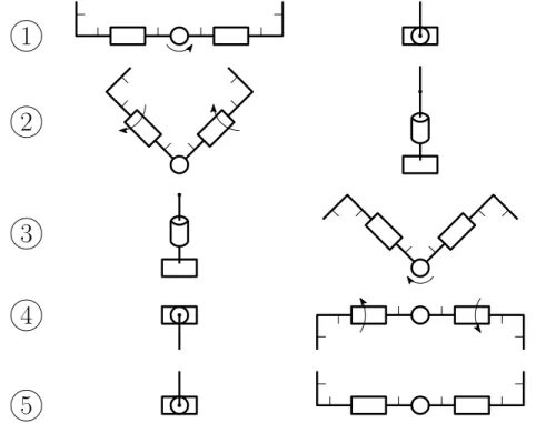
A very different reorientation can be obtained by a slight variation of the sequence, while keeping the same robot architecture. As shown in Figure 2.2, by reversing the direction of rotation of joint 1 or joint 3, the robot performs what can be compared to a "signal flag" motion (Kulwicki et al.,1962) (referred to as manoeuvre B). Concretely, this allows for net rotations mainly about the yaw axis of the robot, while manoeuvre A allows for net rotations about the roll axis.
1
2
4
3
5
Figure 2.2 – Description of manoeuvre B : Front view, manoeuvre steps for a four-body, three-joint architecture (left). Side view, manoeuvre steps for a four-body, three-three-joint architecture (right). Thinner line stubs show link orientation.
Manoeuvres such as those presented above, when executed in free fall, have the interesting characteristic of being time-independent. In other words, the speed at which the manoeuvre is executed has no impact on the final state of the system : only the geometric path in the joint space matters. A mathematical proof of this property can be found in (Shapere,1988). Thus, we can use a representation of the paths in joint space without losing significant information, and use this to our advantage for easier parametrization of the trajectories. The proposed manoeuvres for the simplified three-joint architecture are therefore represented as a closed path in the joint space.
2.5
Mathematical Background
In order to provide a better understanding of the physics at play during the reorientation, the dynamic model of a free-floating serial robot with n links and j revolute joints (j = n − 1) is derived in this section. The formulation presented here was proposed in (Bettez-Bouchard and Gosselin,2016) as an adaptation of (Dubowsky and Papadopoulos,1993).
Free-floating manipulators differ from their earth-based counterparts in that the position and orientation of each link depend on the position and orientation of every other link in the chain (Wittenburg, 2007). As a consequence of the conservation of momentum, the dynamic behaviour of a free-floating multibody system can be expressed with respect to its global centre of mass (CM ), as shown in Figure2.3. Since the position of the CM is constant in a reference frame R0 moving with the robot, the position ri and velocity vi of the centre of mass (CMi) of link i (i = 1, . . . , n) is related to that of the other bodies as follows
n X i=1 miri = 0 , n X i=1 mivi= 0 (2.1)
where mi is the mass of link i. Moreover, the conservation of the angular momentum leads to dh dt = 0 , h = n X i=1 (Iiωi+ miri× vi) (2.2)
where h is the angular momentum, Iiis the inertia tensor of link i and ωiis its angular velocity. As previously stated, it is assumed that the robot is initially at rest (ωi = vi= 0, i = 1, . . . , n) and that no external torque is applied to it during the reorientation, thus h is set to 0. To compute (2.2), each term must be expressed in the same reference frame, in this case R0. The rotation from reference frame i − 1 to reference frame i can be expressed with matrix Qi. Using an axis angle representation, θi is the rotation angle about unit vector ei (expressed in its local reference frame) corresponding to the axis of the ith revolute joint. Matrix Q1 corresponds to the rotation from the inertial reference frame to link 1. The representation in R0 is then obtained by pre-multiplying by the product of rotation matrices Q1 to Qi in the case of a vector, and also by post-multiplying by the transpose of these rotation matrices in the case of a tensor.
Next, ri, vi and ωi must be explicited. The derivation of these terms is based on the concept of barycentre (Wittenburg, 2007), adapted to free-floating serial manipulators in ( Bettez-Bouchard and Gosselin,2016;Dubowsky and Papadopoulos,1993). For each link, two constant construction vectors are defined, namely r0i and l0i, as shown in Figure 2.3. The underscore implies that the vector or tensor is expressed in its local reference frame. Vector r0i connects CMi to joint i, while vector l0iconnects CMi to joint i − 1.
e
1e
2e
n−1CM
r
01l
02r
02l
0nr
1r
2r
nFigure 2.3 – Geometric modelling of the robot.
Combining these vectors with the mass of the links yields the position of the barycentre c0i, which is given by
c0i= l0iµi+ r0i(1 − µi+1) (2.3) with µi the mass distribution in the robot, given by
µi = 0 i = 1 i−1 P k=1 mk M i = 2, . . . , n 1 i = n + 1 (2.4)
where M is the total mass of the robot. Vector c0i can equivalently be found by adding a point mass M µi to joint i − 1 and M (1 − µi+1) to joint i, which defines an augmented link (Wittenburg,2007). The barycentre then becomes the centre of mass of this augmented link (Dubowsky and Papadopoulos, 1993). New augmented construction vectors can be defined with respect to this centre of mass, as
c∗0i= −c0i (2.5)
r∗0i= r0i− c0i (2.6)
l∗0i= l0i− c0i. (2.7)
Similarly to vector ri, these vectors are fully specified by the configuration of the robot, which depends on the joint angles collected in vector θ. It can be shown that ri can be expressed in terms of the barycentric vectors, which yields
ri = n X k=1
with bki defined using the following rule bki = l∗0k k > i c∗0k k = i r∗0k k < i . (2.9)
Vector ωican be expressed in R0 by adding the angular velocity vector imparted by each joint with the angular velocity ω1 of the first link, which yields
ωi =
ω1 i = 1
ωi−1+ ei−1θ˙i−1 i = 2, . . . , n.
(2.10)
Considering that vector bki is constant in the reference frame moving with angular velocity ωi, vi is obtained as vi= n X k=1 ωk× bki i = 1, . . . , n. (2.11) Equation (2.11) can be rearranged with the help of (2.10), yielding
vi = ω1× ri+ Ciθ˙ (2.12)
where Ci is a matrix of dimension 3 × j which is a function of the construction parameters of the robot.
Equations (2.8), (2.10) and (2.12) can now be substituted into (2.2) — where h is set to zero — to form a system of equations that depends only on the unknowns ω1 and ˙θ. The double vector product obtained in the process can be rearranged as
miri× (ω1× ri) = mi((rTiri)1 − rirTi )ω1 (2.13) with 1 the identity matrix.
Finally, collecting the terms in ω1 on one side and the terms in ˙θ on the other side, a linear system of equations that relates the angular velocity of the first body and the joint velocity vector of the robot is obtained as
Aω1 = B ˙θ (2.14)
where A is a 3×3 matrix and B is a matrix of dimension 3×j, which both depend on the mass of the links, the geometric parameters and the configuration of the robot. This formulation of the dynamic model is general and is applicable to any spatial or planar serial free-floating robot.
2.6
Prototype Design
Based on the simplified three-joint architecture presented in Section 2.4, an experimental prototype was designed and built. A CAD model of the prototype is shown in Fig 2.4. The robot was designed without any on-board electronics except for the motors themselves. One drawback of this design is that it requires an experimental setup where wires must run between each motor and an external controller for power and encoder signals. The measures that were taken to mitigate the influence of the hanging wires are addressed in more detail in Section2.8. The total mass of the robot is approximately 0.3 kg. Machined steel inserts were added to the ends of links 1 and 4 in order to position their centre of mass in a way that favours the reorientation using manoeuvres A and B. Links 2 and 3 are hollow, allowing motors to be mounted inside them. The motors are 4.5 Watt brushed DC RE-max 17 with 24 :1 gearheads and 512 counts per turn encoders.
Link 4
Link 1
Link 2 Link 3
Motors
Figure 2.4 – CAD model of the prototype. Parts in blue are made of 3D-printed ABS plastic. Parts in grey are made of steel.
2.7
Simulation
Using the CAD model, dynamic simulations were performed using Siemens NX to study the effects of various parameters on the dynamics of the robot in zero-gravity. Figure 2.5 shows the progression of manoeuvre A simulated with the CAD model and Figure 2.6 shows the progression of manoeuvre B using the same CAD model.
Figure 2.5 – Dynamic simulation of the robot executing manoeuvre A.
Figure 2.6 – Dynamic simulation of the robot executing manoeuvre B.
1,max , 3,max (deg)
270 202.5 120 135 2,max (deg) 90 60 67.5 30 0 0
Figure 2.7 – Final orientation of the robot after manoeuvre A for different values of maximum joint displacement.
2.7.1 Trajectory in the joint space
The influence of the amplitudes of the movements on the net change in orientation, for ma-noeuvre A, was first investigated. In the joint space, this is equivalent to varying the dimensions of the rectangular loop that represents the trajectory. The final orientation as a function of maximum joint displacement is presented in Figure 2.7.
As it can be observed, the axis describing the net rotation induced by the manoeuvre varies very little with respect to maximum joint displacement. This means that the manoeuvre produces a rotation almost purely about the roll axis of the robot and that undesirable motions around other axes are negligible (almost nonexistent). In addition, the net rotation itself increases smoothly with respect to the maximum movement amplitude of both joints. Therefore, small internal movements of the robot produce a small reorientation while large internal movements
produce a large reorientation, meaning that the manoeuvre behaves predictably. Moreover, with a reasonable displacement limit of 270 degrees for the distal joints and 120 degrees for the centre joint, a net rotation of approximately 180 degrees is predicted by the simulation. For a cat-like reorientation, a half-turn is the worst case scenario, since a rotation of more than 180 degrees is equivalent to a rotation of smaller amplitude in the opposite direction. Practically, rotating in the opposite direction can be done by reversing the direction of rotation of joints 1 and 3.
2.7.2 Moment of inertia of the end links
The effect of different inertial parameters on manoeuvre A was also studied. The starting point of this analysis is the realization that drastically increasing the moments of inertia of links 2 and 3 results in no reorientation. Indeed, having bodies 1 and 4 linked to a very high inertia would be comparable to fixing the stators of motors 1 and 3 in space. For this reason, the study was focused on the moment of inertia of links 1 and 4 about joint axes 1 and 3, respectively. Figure 2.8shows the resulting net rotation for different values of moment of inertia, with the same prescribed joint trajectories for each simulation. For this robot, it can be observed that a moment of inertia of up to approximately 100 kg-mm2 contributes to the desired reorientation, that is, a net rotation of 180 degrees. Increasing the inertia past this point has adverse effects on the manoeuvre, notably inducing a progressively greater amount of off-axis rotation and reducing the net amount of rotation about the principal axis of the robot. Moreover, a greater moment of inertia would require higher torques at joints 1 and 3 in order to accomplish the manoeuvre.
2.7.3 Motor gear ratio and rotor inertia
With free-floating robots, extra care must be taken in the selection of the motors for joint actuation. Indeed, the motors can significantly influence the dynamic behaviour of the robot in free fall, depending on their properties. For instance, a gearmotor with a very high reduction ratio might offer more torque, but its fast spinning rotor may disturb the manoeuvre. To better characterize the influence of the gear ratio and the rotor inertia on manoeuvre A, simulations were performed with different values of these parameters. The results are shown in Figure2.9. It can be observed that for this specific manoeuvre and geometric configuration, increasing both the moment of inertia of the rotor and the reduction ratio results in a greater net reorientation. In other words, a smaller maximum displacement at the joints would be sufficient to achieve a net rotation of 180 degrees about the roll axis of the robot. Still, there is a trade-off between performance, form factor, weight and availability of parts, which explains the choice of a 24 :1 ratio and rotor inertia of 0.1 kg-mm2 for the current robot.