This is an author-deposited version published in:
http://oatao.univ-toulouse.fr/
Eprints ID: 14703
To cite this version:
Petre-Bordenave, Romain and Thebault, Lucie and Desmarres,
Jean-Michel and Alexis, Joël Quantification of the pile-up effect for improving
inverse mechanical analysis by means of nanoindentation. (2014) In:
Design, Test, Integration & Packaging of MEMS/MOEMS, 1 April 2014 -
4 April 2014 (Cannes, France).
O
pen
A
rchive
T
oulouse
A
rchive
O
uverte (
OATAO
)
OATAO is an open access repository that collects the work of Toulouse researchers and
makes it freely available over the web where possible.
Any correspondence concerning this service should be sent to the repository
administrator:
staff-oatao@listes-diff.inp-toulouse.fr
Quantification of the pile-up effect for improving
inverse mechanical analysis by means of
nanoindentation
Romain Petre-Bordenave, Cédric Seguineau
Fialab Toulouse, France romain.petrebordenave@fialab.eu
cedric.seguineau@fialab.eu
Lucie Thebault, Jean-Michel Desmarres
Laboratoire intégré d’expertise CNES (Centre National d’Etudes Spatiales)
Toulouse, France
Jean-michel.desmarres@cnes.fr
Joël Alexis
Université de Toulouse, LGP, ENIT/INPT
Tarbes, France
Joel.alexis@enit.fr
Abstract - This paper deals with the identification of elastic-plastic material properties by means of nanoindentation. A dimensional analysis leads to the identification of a specific parameter based on the estimation of the pile-up effect. This parameter may be used in an inverse analysis. Theoretical aspects and experimental issues are discussed.
Nanoindentation, inverse analysis, pile-up, plastic properties I. INTRODUCTION
The utility of thin-films coatings for microelectronics is not to demonstrate. The evaluation of the properties of such coatings requires fitted experiments such as nanoindentation. For 3 decades, practical methods have been developed and are now commonly used to determine elastic parameters such as Young’s modulus [1]. These methods are based on the exploitation of the load-displacement curve obtained by nanoindentation. However, new applications like flexible integrated circuit (IC) require tools for the determination of elastic but also, plastic material parameters such as the hardening exponent or the yield strength. Insofar as nanoindentation loading imposes an elastic-plastic deformation of the sample, this kind of experiment should be suitable for the plastic parameters determination.
The determination of plastic properties of small volumes, like BGA interconnect, are also concerned insofar as nanoindentation is commonly used to probe the mechanical properties of cross-sectioned balls. The process and microstructural features of the raw material have a great impact on the quality of the final interconnection. The approach exposed in this paper may provide new relevant data on the plastic behavior of BGA balls.
In this paper, we will focus on the pile-up volume measurement (Vb) in order to identify elastic-plastic
parameters.
I. THEORY
The usual approach is based on the Oliver & Pharr method [1]. Young’s modulus and hardness are the two material properties that can be identified using standard method. In order to determine plastic parameters like the hardening exponent as well as the yield strength, new parameters must be extracted from the nanoindentation experiments.
Several authors work on the use of several geometries of diamond tip. It is well established now that the use of a single pyramidal tip leads to multiple solutions on the yield’s stress and the strain hardening coefficient [2]. Several authors work on the use of a spherical tip in order to deal with this issue [3], and other ones have developed a reverse analysis based on the use of at least two pyramidal tips (often a Berkovich and a cube corner tip) [4,5]. The use of a spherical tip may introduce awkward effects because of its higher sensitivity to roughness and the difficulty to probe small volumes (like a cross-section BGA). On the other hand, the use of several pyramidal tips is time consuming and the current associated reverse analyses tend to lack of robustness.
Another approach may be based on the measure of second order effects while indenting the material with only one tip. The main difficulty is to determine a measure which is independent from the two previous measures. That is why we have focused on measures independent from the nanoindentation curve, where lot of authors have already
considered parameters like the residual depth or the irreversible work [6]. For example, the method developed by Tunvisut is based on the accurate measurement of imprint contact area [7]. From our point of view, one of the most important second order effect is the pile-up effect around the tip. Indeed, for elastic-plastic materials, the material tend to flow around the tip and to form an irreversible pile-up around the tip. Its volume should be dependent of several material properties and of the geometry of the tip. In order to keep the useful scale independent behavior of the Berkovich indentation, the ratio of the pile-up volume on the indent volume should be considered.
A dimensional analysis was performed using the Vaschy-Buckingham theorem. To perform this analysis five parameters were considered as relevant: hm, E, Y, n and θ
(Fig.1). hm is the maximal depth of penetration , E is the
reduced Young’s modulus (eq. 1), Y is the Yield strength of the material, n is the hardening exponent and θ is the apical angle of the nanoindenter tip.
Figure 1. Height measurements of an imprint [1]
This analysis leads to an implicit relationship expressed as follow: , , . 3 E n Y A h V B c m b
This parameter B that we propose to study is obtained by following the same approach than the one developed by Cheng & Cheng in 1998 [8]:
, , . 4 2 E n Y E h F m , , 5 n E Y W W W tot u tot
As a consequence, three influencing factors are identified. Resolving the corresponding equations stays the second step, and has been addressed with a specific experimental design. In the first place, mixed-effects were not studied.
In this study, two materials were tested in order to have different hardening exponents n, pure copper and 2024 aluminum alloy. Three indenter tips were used to make θ vary, a Cube corner tip, a Berkovich tip and a 3 faces 50° tip. Finally, the ratio ψ=Y/E was modified by work-hardening on a tensile testing machine. In order to perform the hardening, shoulder flat specimen were chosen. These specimens were also annealed to remove the hardening induced by thermomechanical treatments. In these conditions, we can obtain a controlled hardening rate (in the tensile direction).
II. RESULTS
From an experimental point of view, the measurement of
Vb is a relatively important source of inaccuracy. The
difficulty of this measurement lies in the ability of the operator to determine accurately the border between the pile-up and the unaffected surface of the specimen.
Several methods were evaluated in order to estimate the pile-up volume. These methods are based on surface alignments and zero detection. Multiplying methods and operators lead us to estimate the current uncertainty of the method to about 50%.
The reduction of that error was a priority and was performed using a motorized table embedded with the nanoindentation setup. This system consists in a piezo-electric sample-holder that permits to move the sample over two axes. The scan is performed by using this system in combination with the nanoindenter tip. The scanning is done thanks to the table whereas the nanoindenter tip records the height of each point like an AFM in contact mode.
The AFM and the nanovision scan have been compared. On the one hand the AFM offers a greater accuracy thanks to a smaller apex angle, a reduced tip defect and a more accurate Z-sensor. On the other hand the embedded scan can be used for a subtraction of the initial surface roughness as previously described. The embedded scanning system requires the application of a small force on the tip in order to hold to contact with the sample surface. This force is much greater than the one used in AFM in contact mode. This can lead to a height measurement error due to the elastic compression of the sample surface. Differences up to 3 nm were observed between AFM height measurement and the embedded ones on aluminum 2024. That error proved to be constant and independent of the method of analysis.
TABLE I. COMPARISON OF TO VOLUME MEASUREMENTMEANS
Pile-up volume (μm3)
AFM Embedded scan with subtraction
Al
2024 0.61 0.32
a. Example of volume measurement on an Al 2024 sample, the volume measurement difference is up to 50% adding the operator bias
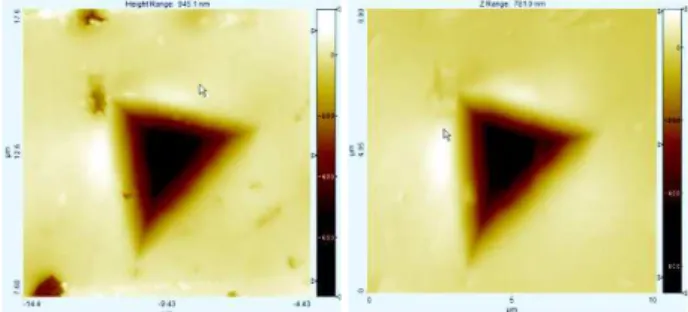
In our case, a new step was added prior to the indentation: a first scanning of the sample surface is done, and the imprint topography is obtained without any roughness by doing the subtraction of the two scans (Fig.2).
Figure 2. Al 2024: Application of the nanovision method on an imprint
This corrected surface was tested under the same conditions as the previous one. The uncertainty has appeared to be reduced down to 10%.
Figure 3. Al 2024: comparison of the AFM scan (left), and the embedded scan with subtraction (right)
Even if the precision of the method is reduced by 5, the accuracy of the method cannot be evaluated without measures on a standard volume. Indeed, the scattering of 50% should be considered on the AFM topography insofar no initial scan can be performed.
In addition, as the bias induced by the applied force is constant, its effect on the pile-up volume measurement can be minimized by increasing the indent depth and hence the pile-up volume.
The inverse analysis performed during this study showed that important errors were due to the neglect of mixed-effects. In order to study those effects with a sufficient accuracy 54 experiments are needed. With a view to simplifying the experimentation, the numerical simulation can be used [9], after the EF modeling were properly fitted to the first experimental results. The goal is here to perform an inverse analysis in order to obtain the same properties by nanoindentation than the properties extracted from a tensile test.
CONCLUSION
Nanoindentation is considered as one of the most convenient mechanical test to evaluate some mechanical properties of materials. In several applications, especially on microelectronics and MEMS technologies, nanoindentation is the only test available to probe the mechanical properties of thin layer, interconnects or other heterogeneous assemblies. Nonetheless, while Young’s modulus is an intrinsic parameter, hardness is not and mainly depends on plastic properties and geometrical effects. In this paper, we have studied the pile-up effect in order to provide a third parameter from the indentation experiment which should be used to estimate intrinsic plastic properties from the experiment (yield stress and strain-hardening coefficient). This parameter is seldom used in the literature insofar as its measure is subjected to high uncertainties. The latter are mainly linked to the small height at stake and involve complementary analyses. In this paper, these two experimental difficulties were addressed when determining a pile-up volume.
We considered the use of a motorized sample holder coupled with the use of the nanoindenter tip like an AFM to probe the height of the surface, before and after the indentation. Subtracting the two surfaces was found to be accurate enough to reduce the uncertainty from 50% to 10%. A comparison with AFM measurement trends to prove that the load applied to keep contact between the tip and the surface lead to a constant bias of about 3 nm on the height evaluation, which may lead to a systematic bias of about 20% on the pile-up volume. More studies should be performed to deal with this systematic bias.
This approach is based on hypotheses on the nature of parameters ruling the pile-up behavior. It appears that the friction coefficient may be a parameter of interest in order to improve the accuracy of inverse analysis. Indeed, few publications mention the study of this parameter on the mechanical behavior of the material under the diamond tip. Adam and Swain have recently exposed that this parameter seems to have a limited impact on the depth volume of bones material (10 to 20%) while the impact on the pile-up is much greater, with a reducing of 50 to 75% of the predicted height of the pile-up [10]. The ratio between the indentation volume and the pile-up effect may then be greatly impacted by the friction coefficient, and should be considered for further investigations.
BIOGRAPHY
Romain Petre-Bordenave is graduate from the ENIT (Ecole Nationale d'Ingénieurs de Tarbes, France) where he obtained his M.Eng. in mechanical engineering. He also obtained a MA in material research from the UPS (Université Paul Sabatier, Toulouse, France). After an internship within the CNES (Centre National d'Etudes Spatiales), he's currently working as research engineer for Fialab, a company that provides failure analysis services.
REFERENCES
[1] W.C. Oliver, G.M. Pharr,“Measurement of hardness and elastic modulus by instrumented indentation: Advances in understanding and refinements to methodology”, J.Mater.Res.,Vol.19,No.1, January 2004,. [2] M. Dao, N. Chollacoop, K.J. Van Vliet, T.A. Venkatesh and S. Suresh, “Computational modeling of the forward and reverse problems in instrumented sharp indentation”, Acta Materialia, vol. 49, n 19, 2001, pp 3899-3918
[3] M. Zhao, et al. "A new approach to measure the elastic–plastic properties of bulk materials using spherical indentation." Acta Materialia vol 54, n 1, 2006, pp 23-32
[4] G. Kermouche, J. L. Loubet, and J. M. Bergheau. "Extraction of stress–strain curves of elastic–viscoplastic solids using conical/pyramidal indentation testing with application to polymers." Mechanics of Materials vol 40, n 4, 2008, pp 271-283
[5] J.-L. Bucaille, et al. "Determination of plastic properties of metals by instrumented indentation using different sharp indenters." Acta materialia vol 51, n 6, 2003, pp 1663-1678
[6] A.C. Fischer-Cripps, "A review of analysis methods for sub-micron indentation testing." Vacuum vol 58, n 4, 2000, pp 569-585 [7] K. Tunvisut, E.P. Busso , N.P. O_Dowd, H.P. Brantner, “Determination of the mechanical properties of metallic thin films and substrates from indentation tests”, Philosophical Magazine, A 82, 2002 pp 2013–2023
[8] Y.T. Cheng, C.M. Cheng, “Relationships between hardness, elastic modulus, and the work of indentation, Appl. Phys. Lett., 73, 1998, pp 614-619
[9] T. Fourcade, “Caractérisation de matériaux en couches minces”, thesis of Institut National Polytechnique de Toulouse, 2013.
[10] C. Adam and M.V. Swain, “The effect of friction on indenter force and pile-up in numerical simualtions of bone nanoindentation.” J. of the Mechanical Behavior of Biomedical Materials, vol 4, n 7, 2011, pp 1554-1558
![Figure 1. Height measurements of an imprint [1]](https://thumb-eu.123doks.com/thumbv2/123doknet/3284299.94224/3.892.59.413.461.638/figure-height-measurements-imprint.webp)