HAL Id: tel-01936805
https://pastel.archives-ouvertes.fr/tel-01936805
Submitted on 27 Nov 2018HAL is a multi-disciplinary open access archive for the deposit and dissemination of sci-entific research documents, whether they are pub-lished or not. The documents may come from teaching and research institutions in France or abroad, or from public or private research centers.
L’archive ouverte pluridisciplinaire HAL, est destinée au dépôt et à la diffusion de documents scientifiques de niveau recherche, publiés ou non, émanant des établissements d’enseignement et de recherche français ou étrangers, des laboratoires publics ou privés.
Décrochage tournant dans un diffuseur lisse radial :
Étude de stabilité et effet sur la performance.
Yaguang Heng
To cite this version:
Yaguang Heng. Décrochage tournant dans un diffuseur lisse radial : Étude de stabilité et effet sur la performance.. Mécanique des matériaux [physics.class-ph]. Ecole nationale supérieure d’arts et métiers - ENSAM, 2017. Français. �NNT : 2017ENAM0049�. �tel-01936805�
N°: 2009 ENAM XXXX
Arts et Métiers ParisTech - Campus de Lille Laboratoire de Mécanique de Lille
2017-ENAM-0049
École doctorale n° 432 : Sciences des Métiers de l’ingénieur
présentée et soutenue publiquement par
Yaguang HENG
le 15 Décembre 2017Décrochage tournant dans un diffuseur lisse radial: Étude
de stabilité et effet sur la performance
Doctorat ParisTech
T H È S E
pour obtenir le grade de docteur délivré par
l’École Nationale Supérieure d'Arts et Métiers
Spécialité “Mécanique-matériaux (AM)”
Directeur de thèse : Antoine DAZIN Co-encadrement de la thèse : Najib OUARZAZI
T
H
È
S
E
Président Rapporteur Rapporteur Examinateur Examinateur Examinateur Examinateur JuryM.Jean-Christophe ROBINET, Professeur, DYNFLUID Laboratory, Arts et Métiers ParisTech (Paris)
M. Pascal FERRAND, Directeur de recherche, CNRS. Laboratoire de Mécanique des Fluides et d’Acoustique, Ecole Centrale de Lyon
M. Nicolas BINDER, Professeur associé, ISAE-SUPAERO
M. Antoine DAZIN, Professeur, Laboratoire de Mécanique de Lille, Arts et Métiers ParisTech (Lille)
M. Najib OUARZAZI, Professeur, Laboratoire de Mécanique de Lille, Université Lille 1
M. Alexandre DELACHE, Maître de Conférences, Laboratoire de Mécanique des Fluides et d'Acoustique, Université Jean Monnet de Saint-Etienne
1
N° d’ordre:
École Nationale Supérieure d'Arts et Métiers
T H È S E
présentée en vue d’obtenir le grade deDocteur
en
Mécanique
Par
Yaguang HENG
DOCTORAT DELIVRÉ PAR L’ ÉCOLE NATIONALE SUPÉRIEURE D'ARTS ET MÉTIERS
Titre de la Thése:
Décrochage tournant dans un diffuseur lisse radial: Étude de stabilité et effet sur la performance
Rotating instability in a radial vaneless diffuser: stability analysis and effect on the performance
Soutenue le Decembre 2017 devant le jury d’examen:
Thése préparée au Laboratoire de Mécanique de Lille École Doctorale nº 432: Sciences des métiers de l’ingénieur
Jury
M.Jean-Christophe ROBINET, Professeur, DYNFLUID Laboratory, Arts et Métiers ParisTech (Paris)
M. Pascal FERRAND, Directeur de recherche, CNRS, Laboratoire de Mécanique des Fluides et d’Acoustique, Ecole Centrale de Lyon
M. Nicolas BINDER, Professeur associé, ISAE-SUPAERO M. Antoine DAZIN, Professeur, Laboratoire de Mécanique de Lille, Arts et Métiers ParisTech (Lille)
M. Najib OUARZAZI, Professeur, Laboratoire de Mécanique de Lille, Université Lille 1
M. Alexandre DELACHE, Maître de Conférences, Laboratoire de Mécanique des Fluides et d'Acoustique, Université Jean Monnet de Saint-Etienne
Examinateur Examinateur Examinateur Président Rapporteur Rapporteur
3
Contents
Contents ... 3 List of figures ... 5 List of tables ... 8 Symbols ... 9 Introduction ... 13 1 Literature review ... 15 1.1 Introduction ... 151.2 Rotating stall in turbomachineries ... 15
1.3 Rotating stall in radial diffusers ... 17
1.3.1 In vaned diffusers ... 17
1.3.2 In vaneless diffusers ... 18
1.3.2.1 Three dimensional rotating stall ... 22
1.3.2.2 Two dimensional rotating stall ... 24
1.3.3 Effects of the geometry ... 28
1.3.4 Pressure losses in vaneless diffusers ... 30
1.3.5 Control methods for diffuser rotating stall ... 31
1.4 Research object and method ... 33
2 Experimental study ... 35
2.1 Introduction ... 35
2.2 Experimental test rig ... 36
2.2.1 SHF radial impeller ... 36
2.2.2 Vaneless diffuser ... 37
2.2.3 Brüel & Kjaer condenser microphones ... 38
2.3 Impeller and diffuser performance ... 38
2.3.1 Pressure measurements ... 38
2.3.2 Flow rate calibration ... 41
2.3.2.1 Flow rate from the tank QT ... 42
2.3.2.2 Leakage flow QL1 ... 44
2.3.2.3 Leakage flow QL2 ... 44
2.4 Vaneless diffuser rotating stall ... 45
4
2.4.2 Characteristics of rotating stall ... 49
2.4.2.1 Number of stall cells ... 49
2.4.2.2 Propagation velocity of stall cells ... 51
2.5 Effect of rotating stall on the diffuser performance ... 53
2.6 Effect of the geometrical configuration ... 62
2.7 Conclusions ... 64
3 Linear stability analysis ... 67
3.1 Introduction ... 67
3.2 Hypotheses ... 67
3.3 Linear model ... 68
3.3.1 Dimensional equations and basic solutions ... 68
3.3.2 Dimensionless form ... 71
3.3.3 Linearization ... 72
3.3.4 Normal Modes Analysis ... 73
3.3.5 Solutions of linear stability analysis ... 73
3.4 Results of linear stability analysis ... 77
3.4.1 Critical flow angle and propagation velocity ... 77
3.4.2 The growth rate of stall mode ... 80
3.4.3 Comparison between theory and experiment for case R = 1.5 ... 84
3.4.4 Velocity vector and pressure distribution ... 86
3.4.5 Analysis of the perturbed flow ... 92
3.4.6 Characteristic times associated with the convection of a perturbation ... 95
3.5 Discussions and conclusions ... 97
4 Weakly nonlinear stability analysis... 99
4.1 Introduction ... 99
4.2 Governing equations for finite amplitude disturbances ... 99
4.3 Derivation of the amplitude equation ... 100
4.3.1 First order solutions ... 101
4.3.2 Adjoint problem ... 102
4.3.3 Second order solutions ... 105
4.3.4 Third order solvability condition ... 106
4.4 Comparison with experimental results ... 109
5
5.1 Conclusions ... 111
5.2 Future works ... 113
Appendix A Diffuser leakages ... 115
A.1 Diffuser upper side leakage ... 115
A.2 Diffuser lower side leakage ... 115
Appendix B Frequency spectra ... 117
Appendix C Spectrum analysis ... 121
Appendix D Pressure recovery ... 123
Bibliography ... 127
List of figures
Figure 1.1 Evolutions of rotating stall in shrouded (left) and unshrouded (right) centrifugal impellers (Lennemann and Howard, 1970) ... 16Figure 1.2 Vaned diffuser rotating stall (Lejvar, 2007) ... 17
Figure 1.3 Rotating stall in vaneless diffuser: (a) radial, (b) tangential, and (c) axial velocity distributions. (d) velocity vectors (Dazin et al, 2011) ... 18
Figure 1.4 Variation of non-dimensional rotational speed with the diffuser inlet flow angle (Jansen, 1964(a), Abdelhamid et al, 1979) ... 19
Figure 1.5 Waveforms of the pressure signals at stall conditions: (a) Abdelhamid and Bertrand, 1979 (b) Abdelhamid et al, 1979 ... 20
Figure 1.6 Phase-averaged radial velocity distributions with diffuser radius ratio and axial distance (Shin et al,1998) ... 20
Figure 1.7 Narrow and wide vaneless diffusers (Lejvar, 2007) ... 21
Figure 1.8 Stable operating range of the flow in the vaneless diffuser (Jansen, 1964a) ... 22
Figure 1.9 Effects of the diffuser inlet (a) Reynolds number and (b) flow angle on the wall boundary layer flow angle (Dou and Mizuki, 1998) ... 23
Figure 1.10 Separation locations versus the diffuser inlet flow angle (Dou and Mizuki, 1998) ... 24
Figure 1.11 The critical flow angle and propagation velocity of rotating stall versus diffuser radius ratio (Tsujimoto et al, 1996) ... 26
Figure 1.12 Contours of velocity magnitude from stable to unstable conditions (Ljevar, 2007) ... 27
Figure 1.13 Variation of K (ratio between total losses and wall friction losses) versus the mean inlet flow angle (Dou, 1991) ... 31
6
Figure 1.15 Radial grooves used for stall suppression (Kurokawa et al, 2000) ... 32
Figure 1.16 J-groove structure (Saha et al, 2001) ... 33
Figure 2.1 Experimental test rig ... 35
Figure 2.2 Inner structure of the tank ... 36
Figure 2.3 SHF radial impeller ... 36
Figure 2.4 Vaneless diffuser... 38
Figure 2.5 Brüel & Kjaer condenser microphone (Type 4135) ... 38
Figure 2.6 Pressure measurement in suction pipe ... 39
Figure 2.7 Pressure taps on the diffuser ... 40
Figure 2.8 (a) The Sélecteur BEXHILL: 20 pneumatic channels. (b) Thermo – hygrometer: DOSTMANN T870. (c) YEW digital manometer (Type 2654). (d) Mercury manometer ... 41
Figure 2.9 Leakage flow in the system ... 41
Figure 2.10 Diaphragm on the inlet tank ... 42
Figure 2.11 Flow rate coefficient versus the inner diameter of the diaphragm ... 42
Figure 2.12 Local quantities in the tank and atmosphere ... 43
Figure 2.13 The joint shapes between impeller and diffuser at upper and lower side ... 44
Figure 2.14 Pump and diffuser performance curves (Static pressure rise, the x-axis for the pump and diffuser performance is respectively the impeller flow rate Q and the diffuser flow rate QD) ... 45
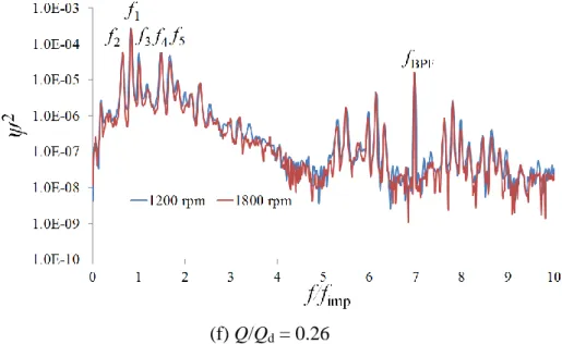
Figure 2.15 Cross-power spectra at two impeller angular velocities ... 46
Figure 2.16 Cross-power spectra at different flow rates ... 49
Figure 2.17 Phase difference in the spectrum ... 50
Figure 2.18 Angle difference between two microphones ... 50
Figure 2.19 Dominant stall mode at Q/Qd = 0.26 (Dazin et al., 2008) ... 51
Figure 2.20 The amplitude (a) and circumferential velocity (b) of stall cells for 1200 RPM .. 52
Figure 2.21 Velocity triangles at impeller outlet (diffuser inlet) ... 52
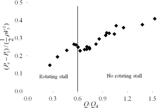
Figure 2.22 Diffuser static pressure recovery versus flow rate ratio (P4 – Diffuser outlet pressure, P3 – Diffuser inlet pressure) ... 53
Figure 2.23 Pressure recovery curve at design flow rate Q/Qd = 1.0 ... 54
Figure 2.24 Moody diagram ... 55
Figure 2.25 Streamline in the vaneless diffuser ... 56
7
Figure 2.27 Experimental Diffuser loss coefficient at diffuser outlet versus length of
streamline ... 58
Figure 2.28 Losses at diffuser outlet versus flow rate ratio Q/Qd ... 58
Figure 2.29 Diffuser losses coefficient versus static pressure recovery coefficient ... 59
Figure 2.30 Radial velocity in the vaneless diffuser at Q/Qd = 0.26 (Dazin et al., 2011) ... 60
Figure 2.31 Two assumed regions in the vaneless diffuser ... 60
Figure 2.32 Assumption of the real streamline ... 61
Figure 2.33 Comparison between experimental losses and corrected losses ... 61
Figure 2.34 Convection at the diffuser outlet ... 62
Figure 2.35 Comparison of the critical flow rate for the dominant stall modes ... 63
Figure 2.36 Comparison of the critical flow angle for the dominant stall modes ... 63
Figure 2.37 Flow field in the vaneless diffuser (Pavesi et al, 2011) ... 64
Figure 3.1 Velocity triangle at impeller outlet ... 67
Figure 3.2 Flow in the vaneless Diffuser ... 68
Figure 3.3 Calculation process of μ and ωreal by Mathematica ... 78
Figure 3.4 Comparisons between present results and Tsujimoto et al (1996) ... 79
Figure 3.5 Critical flow angle (a) and propagation velocity (b) versus the diffuser radius ratio (Ljevar, 2007) ... 80
Figure 3.6 Comparisons of critical flow angle and propagation velocity with experiments (Tsujimoto et al, 1996) ... 81
Figure 3.7 Calculation of σ and ωreal by Mathematica ... 82
Figure 3.8 Growth rates of instabilities for different cases ... 83
Figure 3.9 Propagation velocity of cases R = 2 and 2.5 ... 84
Figure 3.10 Comparison of propagation velocity between experiment and theory (R = 1.5) .. 85
Figure 3.11 The dominant stall mode for R = 1.5 ... 85
Figure 3.12 Comparison of the velocity distribution ... 88
Figure 3.13 Comparison of the radial and tangential velocity components ... 90
Figure 3.14 Comparisons of the pressure fluctuation between present results and literatures 92 Figure 3.15 Contributions of the two parts on the instability: R = 2, n = 4 ... 95
Figure 3.16 New perturbation and the stall cell in the vaneless diffuser ... 95
8
Figure 4.1 Supercritical bifurcation diagram in the case of positive coefficient r (the solid line
represents stable solution while the dashed line represents unstable solution) ... 108
Figure 4.2 Subcritical bifurcation diagram in the case of negative coefficient r (the solid line represents stable solution while the dashed line represents unstable solution) ... 109
Figure 4.3 Slopes of the experimental angular velocity of rotating stall ... 109
Figure B1 Crosspower spectra at all tested flow rates ... 119
Figure D1 Theoretical and experimental pressure recovery in the vaneless diffuser ... 126
List of tables
Table 2.1 Impeller geometries ... 37Table 2.2 Geometries of the vaneless diffuser ... 37
Table 2.3 The radii of 9 pressure taps ... 39
Table 2.4 Technical data of the thermo-hygrometer – DOSTMANN T870 ... 40
Table 2.5 Different modes of rotating stall ... 50
Table 3.1 Critical flow angle for different parameters ... 77
Table 3.2 Critical propagation velocity for different parameters ... 78
Table 4.1 Comparison of the slope of angular frequency ... 110
Table A1 Leakage flow in the vaneless diffuser ... 116
Table C1 Spectrum analysis at Q/Qd = 0.26... 121
Table C2 Spectrum analysis at Q/Qd = 0.36... 121
Table C3 Spectrum analysis at Q/Qd = 0.47... 121
Table C4 Spectrum analysis at Q/Qd = 0.56... 122
Table C5 Spectrum analysis at Q/Qd = 0.58... 122
9
Symbols
Latin letters
Symbol Definition Unit
B2 Impeller outlet width mm
B3 Diffuser width mm
C Constant ()
CP Perimeter of the cross-section of the vaneless diffuser m 2
D Diameter mm
DH Hydraulic diameter ()
DS Diameter of the suction pipe m
f Frequency Hz
fBPF Blade passing frequency Hz
fimp Impeller frequency Hz
frs Rotating stall frequency Hz
K Mean blade thickness mm
L Length of the streamline in the vaneless diffuser m
n Number of stall cells/number of modes ()
N Rotational speed of impeller RPM
p Pressure of the perturbation Pa
P Pressure Pa
Patm Atmospheric pressure Pa
PBEP Total pressure rise of the impeller at best efficiency point Pa
PD Pressure at diffuser inlet Pa
Pm Microphone pressure Pa
m
P Microphone pressure fluctuation Pa
Ps Pressure in the suction pipe Pa
Q Volume flow rate m3 s-1
QBEP Flow rate at best efficiency point m
3 s-1
Qd Design flow rate m
3 s-1
QD Flow rate in the vaneless diffuser m
3 s-1
QT Flow rate from the inlet tank m
3 s-1
QL1 Leakage flow rate at suction pipe - impeller m
3 s-1
QL2 Leakage flow rate at impeller – vaneless diffuser m
3 s-1
10
r Radial position mm
rs Specific speed ()
R Diffuser radius ratio ()
Ra Roughness mm
Re Reynolds number ()
S Area m2
SD Inlet area of the diaphragm m
2
t Time s
T Temperature ºC
u Velocity of the perturbation m s-1
U Impeller tip speed m s-1
V Absolute velocity m s-1
Vr Radial component of the absolute velocity m s
-1
Vθ Tangential component of the absolute velocity m s-1
Z Number of blades ()
Greek letters
Flow angle of the streamline in the vaneless diffuser º
c Critical flow angle for rotating stall º
Impeller outlet blade angle º
ω Angular velocity rad s-1
ωimp Angular speed of impeller rad s-1
ωr Theoretical angular velocity of rotating stall rad s
-1
ωs Specific speed of impeller ()
Density kg m-3
1/tan ()
Wrap Angle of the streamline °
Friction factor ()
ψ Scaled amplitude of the pressure fluctuation ()
σ Growth rate of the instability s-1
ζ Vorticity s-1
Loss coefficient ()
s Loss coefficient at stable conditions ()
Г Circulation m2 s-1
11
1 Impeller inlet
2 Impeller outlet
3 Diffuser inlet
4 Diffuser outlet
① ⑨ Location of the pressure taps from diffuser inlet to outlet (1) First order of the nonlinear terms
(2) Second order of the nonlinear terms (3) Third order of the nonlinear terms
B Basic
c Critical
imp Impeller
real Real part
r Radial direction
θ Tangential direction
z Z direction
Superscripts and signs
Complex conjugate or dimensional quantities
→ Vector
~ Perturbation quantities
Δ Step / Difference
rot Curl
13
Rotating instability in a radial vaneless diffuser:
stability analysis and effect on the performance
Introduction
Turbomachineries are important parts of many devices in modern society, and are widely used in many domains such as water supply, aeronautics, ships, air-conditioning system etc.
The design of turbomachineries can be focused on many aspects. One of them is to increase the operating range of the machine. At partial flow rates, the operating range is limited by the occurrence of unstable phenomena. One of them, which is named rotating stall, has attracted more and more attention in the recent years. Rotating stall has many negative effects, such as noise, vibration, and particularly overall performance reduction. Therefore, the presence of rotating stall is not only threat for the machine itself, but also for the system surrounding it. It is known as a local phenomenon which exists in several passages or components of the machine (example: inducer, impeller or diffuser). The full developed rotating stall often turns into surge, another notable unstable phenomenon which affects the whole system. The present study is focusing on one type of rotating stall which is occurring in radial vaneless diffusers of centrifugal turbomachineries.
In the recent years, one of the test benches of the Laboratoire de Mécanique de Lille was the support of experimental and numerical studies on this topic. In a wide vaneless diffuser, Ljevar et al (2005, 2006a-e and 2007) associated the onset of rotating stall to the two-dimensional core flow instability by using a two two-dimensional numerical model. This numerical model also has been used to analyze the physical aspects of the instability and to evaluate the effects of geometry parameters. 3D unsteady numerical simulation with a SAS (Scale-Adaptive Simulation) turbulence model was applied on this test bench to study the characteristics of rotating stall in the vaneless diffuser (Pavesi et al, 2011). It has been shown that these kinds of simulation are able to predict reliably the occurrence and characteristics of rotating stall. However, this kind of computations (completely 3D and fully unsteady) is very time consuming. Wuibaut et al (2001, 2002a and b) successfully applied PIV technique to the characterization of velocity distributions in one vaneless diffuser. Using the same technique, Dazin et al (2008 and 2011) identified the characteristics and topology of stall cells in a vaneless diffuser. The results have shown that each cell is composed by two cores with inward and outward radial velocity, and rotating stall is characterized by the development of several rotating cells rotating around the diffuser at a speed which is a fraction of the impeller rotational speed. Further analyses have shown that different stall modes which are characterized by different number of stall cells can exist intermittently at one given flow condition. More detailed of these previous studies are presented in the later literature review.
14
(1) To determine if it is possible to use some 2D stability analysis to get a low cost tool which will be able to predict correctly the occurrence, the characteristics and the effects of rotating stall.
(2) To use these tools to try to determine more clearly the cause of this kind of instability. (3) To conduct some new experiments to have a more complete database to check the
validity of the analytical results. The experimental results are also used to discuss the effect of the rotating stall on the diffuser performance.
This work is divided into 5 chapters:
In chapter 1: A review of rotating stall in turbomachineries is presented to show the state of the art of this unsteady phenomenon. Since rotating stall has been observed in different turbomachineries (such as compressors, pumps, etc), their mechanisms and characteristics are summarized. A special focus is made on radial vaneless diffuser rotating stall. Many studies have shown that the behaviors of rotating stall are affected by the geometries of the machine, such as diffuser width, diffuser radius ratio, impeller blade number, etc. The effects of those geometries on rotating stall are specially classified and summarized.
In chapter 2, the experimental test rig and its instrumentation are introduced. The impeller and vaneless diffuser performance are also presented in this chapter. Based on this test rig, the characteristics of rotating stall have been experimentally analyzed, and then the effect of rotating stall on the diffuser performance is investigated.
In chapter 3, a linear stability analysis is presented to characterize rotating stall in the wide vaneless diffuser. The flow in this kind of wide vaneless diffuser is assumed to be two dimensional and axisymmetric, and the fluid is assumed to be incompressible and inviscid. The continuity equation, momentum equations and vorticity equations are written and solved with specific boundary conditions, and the calculated characteristics of rotating stall have been compared to the experiment and the results in literatures. The modes growth rates are used to determine the dominant stall mode. Through the comparisons, the abilities and limits of the linear stability analysis is summarized. At last, a discussion on the cause on of the instability, based on the kinetic energy of the perturbed flow and on the characteristics time associated with the convection of a perturbation are proposed.
In chapter 4, a nonlinear analysis is proposed to take into account the nonlinear combinations which are neglected in the linear analysis. The solutions are extended to the three orders: the first order solutions are the same as the linear ones. The second order solutions have been proposed and verified, and the solvability of the third order results is discussed.
In chapter 5, the conclusions in this study are summarized, and the future works are suggested.
15
Chapter 1 Literature review
1.1 Introduction
The behavior of work-absorbing turbomachines operating at off design conditions, and especially at partial flow rates, is subject to instability phenomena that could affect their performance and can be dramatic for the machines or their environment. The two most studied instabilities are known as rotating stall and surge, and it is proved in many studies that rotating stall is prior to surge (Senoo and Kinoshita, 1978; Day, 1993 and 1999; Bianchini et al, 2013; Biliotti et al, 2015). Therefore, to improve the safe margin and widen the operating range, rotating stall should be well understood. As rotating stall have been found in many kinds of turbomachineries, the mechanisms, characteristics and general conclusions of rotating stall in each type of turbomachineries are briefly summarized. A special focus is made on the vaneless diffuser rotating stall. The research objective and method of the present study are then introduced.
1.2 Rotating stall in turbomachineries
As a very common unstable phenomenon, rotating stall has been widely studied in many aspects. This phenomenon, which appears at partial flow rate, is characterized by the fact that certain portions of the annulus of blades appear to be stalled while others remain unstalled. In addition, these patterns do not remain fixed to the rotor or the stator, but rotate at a velocity which is a fraction of the rotor velocity. The result is that the blades are exposed to very high, low frequency, aerodynamic load variations. For the stall inception in axial compressors, Mathioudakis and Breugelmans (1985) found that rotating stall is triggered by the interaction between the blade surface boundary layer separation and the blade passage flow. Garnier et al (1990) and Hoying (1995) found that rotating stall is sometimes preceded by periodical pressure waves. The waves evolved into rotating stall smoothly without any sudden change of phase or amplitude. They indicated that the rotating waves and rotating stall are the same phenomenon but at different stage. McDougall et al (1990), Day (1993), Camp and Day (1997) and Inoue et al (2000) concluded that two types of stall inception can exist in low speed axial compressors, which are known as spike and modal oscillation. Spike is a short-length-scale disturbance which is characterized by a sharp peak in the velocity and pressure signal. The appearance of spike stall is related to the local flow separation in the blade row, and occurs when the critical incidence is exceeded. Modal oscillation is a long-length-scale disturbance which grows smoothly into rotating stall. It gives rise to flow separations in a larger number of blade passages, results in broader, slower rotating stall cells, and this cell formation is attributed to the flow separation near the hub side. Day et al (1999) reported that the type of stall inception is strongly depending on the compressor rotational speed. Spike type stall occurs at low rotational speed and it possibly turns into modal oscillation when the rotational speed is increased to a certain value. A typical evolution of short-length-scale stall to long-length-scale wave in axial compressor has been shown in Inoue et al (2000). Numerical simulations also have been applied to study the axial compressor rotating stall in the aspects of their effect and characteristics (Saxer-Felici et al, 1999; Crevel et al, 2014; Dodds and Vahdati, 2015).
16
In centrifugal turbomachineries, rotating stall also received a great attention. Lennemann and Howard (1970) illustrated the different stall evolutions in shrouded and unshrouded centrifugal impellers. The stall originates from the flow separation generated at the blade suction or pressure side, as shown in Figure 1.1. Arnulfi et al (1996) studied the stall inception at two-stage and four-stage centrifugal blowers. The results showed that the characteristics of rotating stall in the two configurations are almost the same for all flow conditions, and stall inception occurs almost at the same time in all components. It is then concluded that the onset of rotating stall is only depend on the interaction between the impeller and diffuser. Bianchini et al (2015) illustrated the evolution of stall to surge by using a real time analysis. It has been shown that with a further reduction of the flow coefficient, the rotating stall pattern was first replaced by a new and more intense rotating phenomenon, coupled with the onset of e surge conditions. Finally, surge conditions were reached and the pressure fluctuations in the diffuser are replaced by a uniform pressure field, associated with the mass-flow oscillations.
Figure 1.1 Evolutions of rotating stall in shrouded (left) and unshrouded (right) centrifugal impellers (Lennemann and Howard, 1970)
Since the stall inception is characterized by several phenomena, it can be predicted by monitoring the corresponding phenomena. For example, Lawless and Fleeter (1995) studied the spatially coherent pressure waves to warn the arising of instability in a low speed centrifugal compressor. Using some sensitive microphones which have been arranged on the diffuser and around the compressor inlet, and with a Fourier analysis, the experimental results showed that the transition from stable condition to stall condition is a gradual process, and the pressure waves which are used to warn the stall inception is 26 impeller revolutions before a full developed stall. Kang JS and Kang SH (2001) found that the stalling process in a centrifugal compressor is related to the impeller rotational speed, a stall warning is proposed based on the spectrum at impeller frequency. The tested warning time is about 200 impeller revolutions. Another method, which is called traveling wave energy method has also been proved to be a reliable method, and the warning time is 100 impeller revolutions for low impeller speed and 1000 impeller revolutions for high impeller speed.
The occurrence of rotating stall always causes extra loads on the machine, which is a strong threat for the system stability and safety. The pressure fluctuations and vibrations due
17
to rotating stall have been studied by Lucius and Brenner (2011), Bianchini et al (2013) and Biliotti et al (2015).
1.3 Rotating stall in radial diffusers
In general, the flow coming from centrifugal impeller outlet has a great kinetic energy. Therefore, diffusers are widely used to convert the kinetic energy into pressure, and also help to keep the flow uniform. There are two families of diffusers: vaned diffuser and vaneless diffuser, and many studies have shown that rotating stall can exist in both of them. Actually, it also has been shown that the use of diffusers is always accompanied by rotating stall when the machine is operating at partial flow rates. This was experimentally reported by Abdelhamid and Bertrand (1979), Abidogun and Ahmed (2000), and Biliotti (2013). They found that the flow always became unstable at a certain condition when the machine is operating with a diffuser. However, the mechanisms of rotating stall in these two kinds of diffusers are different, and even only in the vaneless diffuser, different mechanisms which are responsible for the onset of rotating stall can be found.
1.3.1 In vaned diffusers
The mechanism of rotating stall in vaned diffusers is similar to the one that can be found in inducers or impellers, which is associated with local flow separation over the blades or vanes at large positive incidence angles. This kind of rotating stall have been studied by many authors (Tramm and Dean, 1976; Lakshminarayana and Runstedler, 1980; Ötügen et al, 1988; Yoshida et al, 1991; Sinha et al, 2001; Sano et al, 2002). Lejvar (2006) illustrated a typical vaned diffuser rotating stall, as shown in Figure 1.2, where three passages are stalled. The stalled area is called a stall cell, which is characterized by a reduced or no through flow. Rotating stall is formed by several of this kind of stall cell, and propagates in the same direction as the impeller, with a speed which is a fraction of the impeller speed.
18 1.3.2 In vaneless diffusers
Rotating stall in the radial vaneless diffuser is somehow different than in other machines due to the non-vane/blade structure, it is not a real stall but a stall-like unstable phenomenon which occurring at partial flow rate. With the similarity to the rotating stall in other machines, it is also named as vaneless diffuser rotating stall. This kind of rotating stall has been extensively studied in many aspects: experimental studies can be found in Abdelhamid and Bertrand (1979), Abdelhamid et al (1979), Abdelhamid (1981), Ligrani et al (1982), Frigne and van den Braembussche (1984), Abidogun and Ahmed (2000), Ferrara et al (2004), Abidogun (2006), Dazin et al (2008 and 2011), and theoretical analyses were presented by Jansen (1964a), Senoo et al (1977), Abdelhamid (1980), Frigne and van den Braembussche (1985), Moore (1989 and 1991), Tsujimoto et al (1996). Several numerical simulations can be found in Ljevar et al (2005, 2006a-e), Ljevar (2007), Pavesi et al (2011).
In Figure 1.3, the PIV results presented by Dazin et al (2011) have clearly shown the topology of rotating stall in a vaneless diffuser. In this case, three stall cells can be identified. Each cell is located near the outlet of the vaneless diffuser, and is composed by two cores with inward and outward radial velocities. These stall cells propagate in the same direction as the impeller rotational direction, and their propagation velocity is proved to be a fraction of the impeller speed (Dazin et al, 2008). This also can be seen from Figure 1.3(b), the stalled regions are characterized by relative negative tangential velocity. In the axial direction, it has been found that the stall cells are developing in the hub-to-shroud direction.
Figure 1.3 Rotating stall in vaneless diffuser: (a) radial, (b) tangential, and (c) axial velocity distributions. (d) velocity vectors (Dazin et al, 2011)
19
The mechanisms of the vaneless diffuser have been extensively studied, and many studies have revealed that more than one mechanism should responsible for the onset of rotating stall. Abdelhamid and Bertrand (1979) found the measured characteristics of rotating stall in their study are different from the results presented by Jansen (1964a) and Abdelhamid et al (1979) in many aspects, and then they pointed out the possibility of the existence of more than one set of flow conditions which could lead to the occurrence of rotating stall in the vaneless diffuser. The geometrical parameters in these studies are listed as follow:
Jansen (1964a): D4/D3 = 2.93, B3/D2 = 0.068
Abdelhamid and Bertrand (1979): diffuser 1: D4/D3 = 1.83, B3/D2 = 0.038 – 0.063
diffuser 2: D4/D3 = 1.55, B3/D2 = 0.038 – 0.063
Abdelhamid et al (1979): diffuser 1: D4/D3 = 1.51, B3/D2 = 0.032
diffuser 2: D4/D3 = 1.52, B3/D2 = 0.065
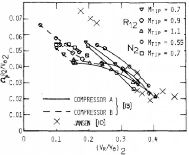
The first difference comes from the comparison of non-dimensional rotational speed of the stall patterns. This rotational speed did not change as the flow rate was reduced after the onset of rotating stall in Abdelhamid and Bertrand (1979), but it increased as the flow rate was decreased in Jansen (1964a) and Abdelhamid et al (1979), as shown in Figure 1.4.
Figure 1.4 Variation of non-dimensional rotational speed with the diffuser inlet flow angle (Jansen, 1964(a), Abdelhamid et al, 1979)
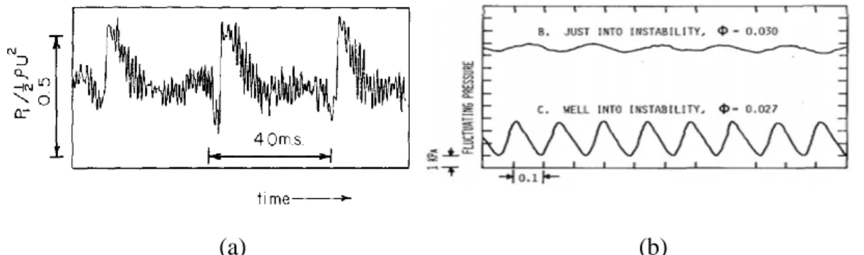
The difference also can be seen in the waveform of the pressure signals at stall condition. The waveform in Abdelhamid and Bertrand (1979) is characterized by a sharp variation while in Abdelhamid et al (1979) the waveform is sinusoidal or almost sinusoidal.
20
(a) (b)
Figure 1.5 Waveforms of the pressure signals at stall conditions: (a) Abdelhamid and Bertrand, 1979 (b) Abdelhamid et al, 1979
More differences can be found in terms of amplitude of the pressure fluctuation and number of lobes. The amplitude of the pressure fluctuation is 11% (of U22), and the number
of lobes varies from 1 to 4 in Abdelhamid and Bertrand (1979), while the amplitude is only about 0.4% - 2%, and only one stall pattern with 2 lobes can be obtained in Abdelhamid et al (1979). Although the geometrical parameters are similar in these two studies, but the observed characteristics of rotating stall are clearly different. It is then concluded that more than one set of flow mechanisms could responsible to the occurrence of rotating stall in the vaneless diffuser.
Shin et al (1998) reported two mechanisms responsible for the development of reverse flow which further results in abrupt rotating stall development in a vaneless diffuser. Figure 1.6 gives the phase-averaged radial velocity distribution at the stall inception for two flow rates ( Q/D2B3U2), the shaded areas represent reverse flow regions. It can be seen that the
reverse flow at is dominated by the extension of the reentering flow from the diffuser exit, and at, it is dominated by the growth of the local flow separation zone on the hub and shroud side.
(a) (b)
Figure 1.6 Phase-averaged radial velocity distributions with diffuser radius ratio and axial distance (Shin et al,1998)
Gao et al (2007) summarized the effects of geometries on rotating stall in the vaneless diffuser by wavelet neural networks. The results have shown that the stall behavior in diffusers with large and small width ratio responds differently for variation of one same parameter. For example, the critical flow angle is found to increase with the width ratio in Jansen (1964a), and this result contradicted with Abidogun (2006). This suggests that the stall mechanisms in two kinds of diffuser are possibly different. According to that, depending on the ratio of diffuser width to impeller outlet radius B3/r2, Ljevar (2007) proposed two kind of
21
(B3/r2 0.1), as shown in Figure 1.7. The stall mechanisms in two types of diffuser are
different due to the different forms of the boundary layers.
Figure 1.7 Narrow and wide vaneless diffusers (Lejvar, 2007)
(1) In narrow vaneless diffusers, the mechanism of rotating stall is associated with a three dimensional boundary layer instability. From the diffuser inlet, the boundary layers on both walls gradually develop with the increase of radius, then they merged together and interact with the core flow. The interaction between boundary layers and the core flow will leads to unsteady flow (flow separation, reverse flow, reentering flow, etc) in the flow channel. Consequently, rotating stall could occur when those unsteady flow are combined with the rotating system.
(2) In wide vaneless diffusers, it is assumed that the space between two walls is large enough to have a two dimensional core flow which separates the wall boundary layers from each other. In this case, the mechanism of rotating stall is mainly associated with a two dimensional core flow instability, and the effect of boundary layers on the core flow is weak.
However, one can notice that the diffuser radius ratio r4/r3 is also important to define the
type of diffuser. According to the previous diffuser definition, one can imagine that the boundary layers in a “wide vaneless diffuser” can be in the same situation as in the narrow vaneless diffuser if the diffuser radius ratio is also large enough. Similar considerations have also been reported by Senoo and Kinoshita (1977). They indicated that no reverse flow occurs in a wide vaneless diffuser if the diffuser radius ratio is small enough. Besides, the mass flow rate also strongly affects the development of the boundary layer, the decrease of the mass flow rate results in a smaller diffuser inlet flow angle, and an increase of the length of the streamlines. Consequently, the boundary layer thickness will increase and the flow topology in a wide vaneless diffuser will be similar to the one we have in a narrow vaneless diffuser.
22
Nevertheless, how to define “narrow” or “wide” vaneless diffuser is not clear even if different diffuser geometries can lead to different instability mechanisms. The main focus of next part will be to introduce these different mechanisms of rotating stall in the two kind of vaneless diffusers.
1.3.2.1 Three dimensional rotating stall
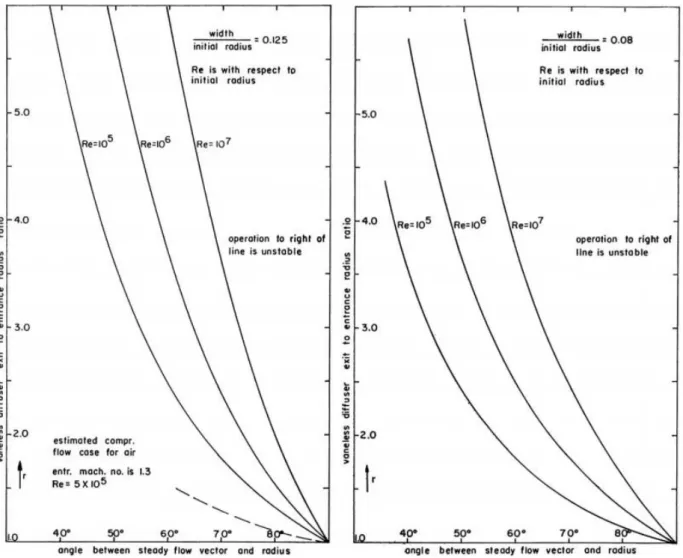
Three dimensional rotating stall in vaneless diffusers, associated with a flow separation or a reverse flow due to the boundary layer instability, have been extensively studied. This kind of diffuser stall has been studied with the help of the boundary layer theory. Jansen (1964a) found that a steady flow may change into rotating stall when the radial velocity component is directed inward along the diffuser side walls. The three-dimensional boundary layer theory used in Jansen (1964b) indicated that the inward flow take place when a three-dimensional boundary layer separation occurs. Therefore, rotating stall will be expected when a three-dimensional flow separation exists in the vaneless diffuser. The criterion to predict the boundary layer separation is given in Figure 1.8. The flow separation (or rotating stall) will be present when the machine is operated in the region on the right of the curves.
23
Using the same boundary layer theory, Dou and Mizuki (1998) indicated that the location of the flow separation varies with different parameters. In Figure 1.9, the value of w = 0
indicates the separation location. It can be seen that with a given diffuser inlet flow angle º, the flow separation is closer to diffuser inlet with the increase of Reynolds number (Figure 1.9(a)). On the other hand, Figure 1.9(b) shows that the separation is moving to the diffuser inlet with the decreasing flow angle when the Reynolds number is fixed. Therefore, the physical mechanism of the onset of rotating stall is explained as: with the decrease of flow rate, the flow separation or the reverse flow zone moves to the diffuser inlet and interacts with the rotating jet-wake flow pattern discharged from impeller outlet, and rotating stall is then generated. The importance of the interaction between jet-wake pattern and the reverse flow on the diffuser instability also haven been reported by Mizuki et al (1985). Some other studies of the jet-wake pattern can be found in Dean and Senoo (1960), Johnston and Dean (1966) and Cumpsty (1989).
More studies of rotating stall associated with the three-dimensional boundary layer theory can be found in Senoo and Kinoshita (1977), Senoo et al (1977), Frigne and van den Braembussche (1985).
(a) (b)
Figure 1.9 Effects of the diffuser inlet (a) Reynolds number and (b) flow angle on the wall boundary layer flow angle (Dou and Mizuki, 1998)
24
Figure 1.10 Separation locations versus the diffuser inlet flow angle (Dou and Mizuki, 1998)
1.3.2.2 Two dimensional rotating stall
As it has been introduced before, rotating stall in a wide vaneless diffuser is associated with the two dimensional core flow instability which appears when a critical flow angle is reached, and the effect of the boundary is weak and can be neglected. Studies for this kind of rotating stall have been presented by Jansen (1964a), Abdelhamid (1980), Moore (1989 and 1991), Tsujimoto et al (1996), Ljevar et al (2005, 2006a-e and 2007).
Jansen (1964a) has not only indicated that the occurrence of rotating stall is linked with the three dimensional boundary layer separation, but also proposed a two dimensional theoretical model to determine the stability of the two dimensional diffuser core flow. It was assumed that the diffuser flow in the vaneless diffuser is two dimensional, incompressible and inviscid, and the perturbed flow is treated as the superposition of a steady and a perturbed flow. The model is constructed by the continuity and momentum equations, and the solution which expresses the perturbation in periodic waves is given in the following form:
( )
( )
r e
i t
(1.1) where is a complex number,
re
i
im
(1.2)In this analysis, represents the number of stall cells, and re is the angular velocity of
rotating stall. The stability criterion for the two dimensional flow is determined by the sign of im, the perturbations grow for im < 0, decay for im > 0, and keep constant for im = 0. That
25
With the same assumption of the diffuser flow as Jansen (1964a), Abdelhamid (1980) proposed a theoretical analysis to estimate the effects of relevant parameters on the stability limits. The flow properties were written as a mean flow plus the perturbations,
( , ) ( , , ) ( , ) ( , , ) ( , ) ( , , ) r r r V V r u r t V V r u r t p p r p r t (1.3)
The linearized equations were obtained and the perturbations were written in a form similar to the one proposed by Jansen (1964)
( ) ( ) ( ) ( , , ) ( ) ( , , ) ( ) ( , , ) ( ) i t m r r i t m i t m u r t u r e u r t u r e p r t p r e (1.4)
The model was solved with specified boundary conditions. The determination of stable or unstable regimes has been done by introducing a small imaginary part to the quantityr V2 / 2. Based on this model, the effects of diffuser radius ratio, diffuser inlet flow angle, frequency of the oscillation, and number of stall cells have been discussed, the general conclusions are
(1) Diffusers with small radius ratio are more stable than the large ones.
(2) The decrease of diffuser inlet flow angle leads to the decrease of diffuser stable margin. (3) Depending on the boundary conditions, diffuser stable margin responses differently
for the increase of number of stall cells.
(4) The coupling between the impeller and the diffuser is important to the generation of self-excited oscillation. The diffuser flow maybe stable with one impeller, but unstable with another even with the same diffuser inlet flow angle.
Tsujimoto et al (1996) presented a two dimensional inviscid flow analysis to study the characteristics of rotating stall in vaneless diffusers. It is assumed that the vorticity is transported on the steady flow which is given by:
2 2 r Q V r V r (1.5)
It is also assumed that the relative flow exits the impeller tangentially to the vanes, then the following condition can be obtained by:
2 r2cot
v v (1.6) where is the vane angle.
26
The linear model is constructed to give the solutions for the disturbance velocity components and the vorticity. In the subsequent simplified case, the boundary conditions of vanishing velocity fluctuation at thediffuser inlet and vanishing pressure fluctuation at the diffuser outlet are applied, that is, for the velocity fluctuations at the diffuser inlet:
2 2 0
r
v v (1.7) and for the pressure fluctuation at diffuser outlet:
3 0
p (1.8) It is interesting to note that the above condition (1.6) associated with the impeller parameter is always satisfied by the proposed boundary condition (1.7) regardless the vane angle. Therefore, this simplified analysis is independent on the upstream impeller. A further analysis also showed that the diffuser rotating stall is nearly unaltered even if a more realistic flow taking into account: the impeller is used as an inlet flow condition.
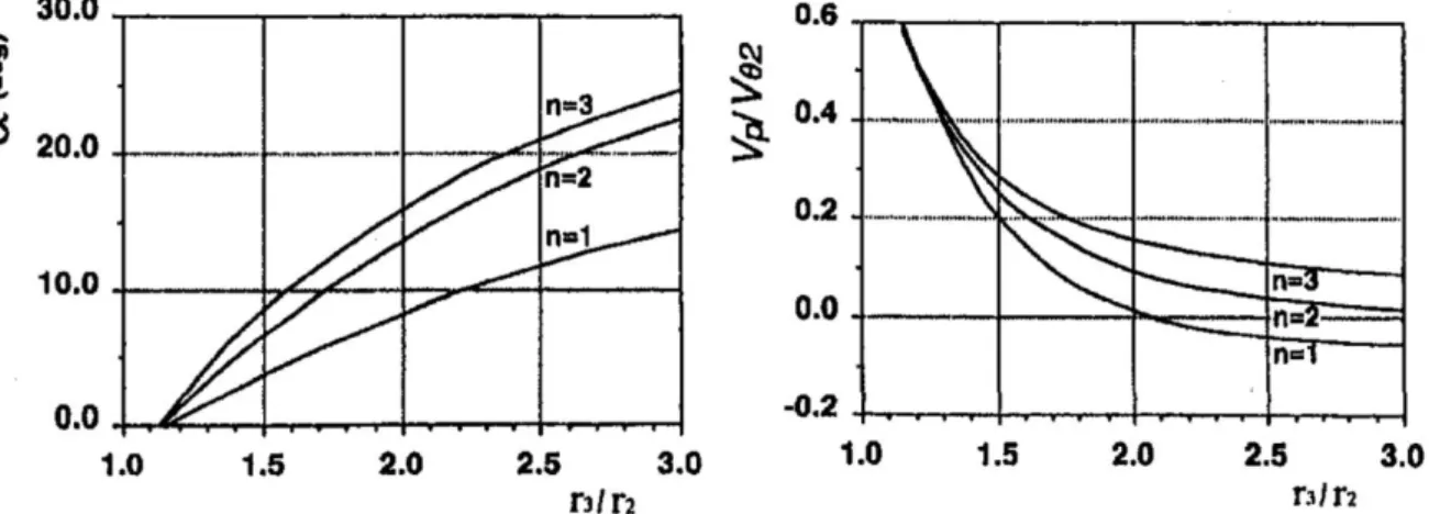
If the diffuser radius ratio and the number of stall cells are given, this analysis is able to calculate the corresponding flow angle and propagation velocity of the stall mode at critical condition, as shown in Figure 1.11, where the flow angle is defined as the angle between the flow path and the tangential direction: arctan(Vr /V)
Figure 1.11 The critical flow angle and propagation velocity of rotating stall versus diffuser radius ratio (Tsujimoto et al, 1996)
The general conclusions for this two dimensional analysis are
(1) Rotating stall occurs when the critical flow angle is reached. The critical flow angle and propagation velocity are the functions of the diffuser radius ratio and number of stall cells, and independent on the impeller.
(2) The critical flow angle is larger for larger number of stall cells when the radius ratio is fixed, and is larger for larger radius ratio when the number of stall cells is given. (3) Smaller propagation velocities are observed for larger radius ratio.
27
In addition to theoretical analysis, two dimensional rotating stall have also been numerically simulated by Ljevar et al (2005, 2006a-e, and 2007). The studied vaneless diffuser is a typical wide one with a radius ratio equal to 1.52. A laminar incompressible flow model is used, and the jet-wake pattern is prescribed at the diffuser inlet. The transition from stable to unstable conditions is shown in Figure 1.12. It can be seen that at stable condition (m = 11º), counter-clockwise vortices alternate near the diffuser outlet, and the number of the
vortices equal to the number of the prescribed jet-wake patterns; at the unstable condition (m
= 3.9º), two dimensional rotating instability which characterized by seven counter-clockwise rotating vortex structures can be identified. It is believed that this two dimensional rotating instability is associated with rotating stall phenomenon since it develops in few impeller revolutions and characterized by rotating cells which propagate with a fraction of impeller speed around the circumference. This transition is obtained by varying the diffuser inlet radial and tangential velocity, that is the inlet flow angle which is known to be the critical parameter for the occurrence of rotating stall. The authors also suggest that the occurrence of the two dimensional rotating instability is due to the interaction between the diffuser inlet jet-wake pattern and the alternating flow pattern near the diffuser outlet. When the flow angle is large, the jet-wake pattern is more radial toward to the alternating flow pattern, and they gear perfectly into each other. With the decrease of the flow rate, the jet-wake pattern becomes more circumferential. Once it is circumferential enough to pass underneath the alternating flow instead of interacting with it, rotating instability starts to occur. The small and weak vortices merge into larger ones, and finally several cells are formed and equally distributed around the diffuse space.
Figure 1.12 Contours of velocity magnitude from stable to unstable conditions (Ljevar, 2007) This two dimensional simulation has also been applied to study the influence of the geometrical parameters, that is the effect of diffuser radius ratio, diffuser width ratio and the impeller on the stall characteristics.
28 1.3.3 Effects of the geometry
Rotating stall is characterized by several characteristics (number of cells, critical condition, propagation velocity, etc) which can depend on the geometrical parameters of the machine. Therefore, the study of the effects of these parameters on the instability behavior can help to predict the stall at the design phase, this is particular important for industrial application. The main studies that have been conducted on these subjects are summarized as follows.
Diffuser radius ratio: Senoo and Kinoshita (1977) reported that the decrease of radius
ratio helps to suppress the reverse flow which is expected at the rear part of a wide vaneless diffuser, and leads to a decrease of the critical inlet flow angle. Abdelhamid (1981) found that the rotational speed of stall cells varied inversely with the diffuser radius ratio, and that critical flow angle of stall inception increased with the diffuser radius ratio, but the slope the critical angle evolution with the radius ratio decreased significantly when the radius ratio larger than 1.75. Tsurusaki et al (1986), and Tsurusaki and Mori (1988) experimentally observed that the critical flow angle of rotating stall decreases with the decrease of the diffuser radius ratio. Theoretically, Tsujimoto et al (1996) have shown that the critical flow angle increases with the increase of the diffuser radius ratio in a linear stability analysis. The effect of the diffusion ratio reported by Ferrara et al (2004), is actually the effect of diffuser radius raio. It has been found that the radius ratio has a great influence on both of the stall inception and the stall pattern. In a shorter vaneless diffuser, a smaller stall inception flow angle is expected but the stall pattern becomes more complex. The numerical study presented by Lejvar (2007) agrees that the critical angle of rotating stall decreases with decreasing diffuser radius ratio, and the number of cells and their propagation velocity decrease with the increase of the diffuser radius ratio. The propagation velocity of stall cells seems only affected by the size of the diffuser space. She has shown that a larger diffuser radius ratio leads to cells which are far from the diffuser inlet and which are consequently propagating at a lower velocity. As a conclusion, if other geometrical parameters remain unchanged, smaller radius ratio diffusers are more stable than larger ones. The reasons are twofold: on the one hand, the boundary layer get easily fully developed in a diffuser with a large radius ratio. This leads to a flow separation or a reverse flow which is one of the rotating stall triggers; on the other hand, the stable margin for a small radius ratio is wider because the critical condition will be reached at a much smaller flow angle. However, it should be noticed that the decrease of radius ratio also leads to a performance reduction. Therefore, the balance between the stability and performance should be carefully considered.
Diffuser width ratio: Jansen (1964a) reported that a decrease of the diffuser width ratio
will increase the flow angle at diffuser inlet, and thus keep the flow angle away from the critical stall condition: the operating range of the system is then increased. Senoo and Kinoshita (1977), and Ligrani et al (1982) also gave similar conclusions about the effect of diffuser width ration on the flow stability. Tsurusaki et al (1986) experimentally plotted the critical flow angle of rotating versus 4 diffuser width ratios, the results have shown that the critical flow angle increase with the increase of diffuser width ratio. Ötügen et al (1988) stated that the onset of rotating stall is delayed with the decreased diffuser width ratio due to the
29
critical flow angle of rotating stall decreases with the decreased diffuser width ratio. Moore (1991) also observed that narrow diffusers are more stable than wide ones, because the boundary layer displacement makes the flow in narrow diffusers more convergent than in wide ones. Ferrara et al (2004) agree that the diffuser width strongly influence the critical flow rate of stall inception, but seems to not influence very much the stall evolution. Ishida et al (2005) found that the operation range of narrow diffuser is larger than wide ones: the unstable flow range of the test blower was reduced about 45% by implementing a narrower diffuser. Lejvar (2007) explained why the stability range is improved in narrow diffuser: first, a narrow diffuser gives additional friction forces which make the flow structure more stable; second, a narrow diffuser increases the radial velocity component. Consequently, the flow angle becomes larger. However, Abidogun (2006) reported that the critical flow rate of rotating stall in a vaneless diffuser increases with the decrease of diffuser width ratio, which is inconsistent with previous studies. He also indicated that the frequency of rotating stall is not affected by the diffuser width ratio, but increases with the increase of diffuser radius ratio: this result is also opposite to what was observed by Ljevar (2007). Nevertheless, it seems that most of the studies agree to say that small diffuser width ratio helps to widen the stable operating range of the system, but leads also to a performance drop.
Impeller: Zhu and Sjolander (1987) studied the effects of the impeller geometry on the
diffuser performance. The main geometrical parameters for the impeller are: blades number, inlet blade angle and outlet blade angle. The results showed that the diffuser performance was not affected by the impeller geometries. Ötügen et al (1988) also reported that the behavior of rotating stall is not affected by the impeller tip speed. Tsurusaki and Ichihara (1988), Tsujimoto et al (1996) have concluded that the vaneless diffuser rotating stall is nearly unaffected by the upstream impeller. Lejvar (2007) indicated that the scaled propagation velocity of cells is independent on the impeller speed and the number of blades, but that the number of stall cells and the critical flow angle vary with the number of impeller blades. As a conclusion, it seems that the diffuser rotating instability is not affected too much by the impeller, diffuser rotating stall is more likely linked to the nature of the diffuser itself.
Diffusion shape: Zhu and Sjolander (1987) studied two kind of diffusers with divergent or
convergent structures. The results showed that the convergent diffuser can help to stabilize the inner flow because it helps to reduce or eliminate the reverse flow which is the main cause of rotating stall in a wide vaneless diffuser. However, the penalty of the convergence diffuser is the performance reduction. Therefore, it is suggested to select an optimised wall convergence angle to satisfy both the performance and the stability requirements.
Clearance between impeller and diffuser : Yoshida et al (1991) performed an
experiment to study rotating stall by changing the clearance between impeller and diffuser. It has been found that the clearance has a great effect on rotating stall. With the decrease of the clearance, rotating stall became weakened and exists in a narrower flow range, which means the flow is more stable with a small clearance. Sano et al (2002) simulated the effect of the clearance between the vaned diffuser and the impeller on the stall inception. The results also showed that a small clearance leads to an increase of the safe margin.
30
Mach number: Senoo and Kinoshita (1977) indicated that the critical flow angle is
affected by the diffuser inlet Mach number, and that the influence is strong for diffuser with large width ratio. The critical flow angle increases with the increase of Mach number because a larger Mach number results in a greater density and consequently a decrease of the flow angle. The influence is strong for large width ratio diffuser because the reverse flow occurs at larger radius and the effect of Mach number is magnified. The results presented by Ferrara et al (2004) also showed that the Mach number strongly influence stall inception flow rate, but does not influence too much on the stall evolution.
1.3.4 Pressure losses in vaneless diffusers
Senoo and Kinoshita (1978) reported that the pressure losses in a vaneless diffuser consist of exit losses and wall friction losses. For diffusers with small radius ratio, the pressure loss is mainly contributed by the exit loss, and it is increased with the increase of flow rate. On the other hand, the pressure losses in large radius ratio vaneless diffuser are mainly coming from the wall friction losses and it increases with the decrease of flow rate.
Dou (1989) concluded that the losses in the vaneless diffuser consist of: mixing losses at the diffuser inlet, the divergence losses caused by the pressure gradient, secondary flow losses, and wall friction losses. The mixing losses are caused by internal friction resulting from the shear stress distribution over the whole inlet cross section of the diffuser passage, and it is mainly focused in the region: D/D2 = 1.00 ~ 1.06. The divergence loss is significant when the
flow angle is large, because the boundary layer easily separates from the diffuser wall due to the large divergence of the passage. On the other hand, the secondary flow loss becomes important when the flow angle is small, because the flow tends to be unstable because of the large curvature of the streamline and the reverse flow. Based on a semi-empirical method, it is found that i/ the total energy loss is strongly depending on the flow angle and the diffuser width ratio, ii/ the friction losses are important in the front part of the diffuser and are small in the rear part.
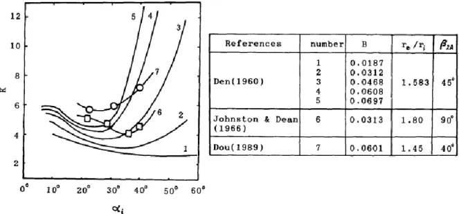
Dou (1991) added that the friction losses are significant when the flow path is long in the vaneless diffuser, consequently, the friction losses should depend on the diffuser width ratio, diffuser radius ratio, diffuser inlet flow angle and Reynolds number. Therefore, this analysis discussed the diffuser losses together with the diffuser width ratio and the inlet flow angle. The results cited from Den (1960), Johnston and Dean (1966) and Dou (1989) are plotted in Figure 1.13.
31
Figure 1.13 Variation of K (ratio between total losses and wall friction losses) versus the mean inlet flow angle (Dou, 1991)
where B is the diffuser width ratio, ro/ri is the diffuser radius ratio, and 2A is the blade angle
at the impeller outlet. K represents the ratio between total losses and wall friction losses. The minimum value of K in each case represents the point for which the wall friction losses are the largest portion of the total losses, and one flow angle i is corresponding to the minimum
K value. When the flow angle is smaller than this value of i, the contribution of the
secondary flow losses increases; when the flow angle is larger than i, the diffusion losses
increase. It can be seen that the friction losses are the primary source of losses in diffuser with small width ratio, and that the other losses are small. On the other hand, the friction losses become a small part of the total losses in large width ratio diffusers especially when the flow angle is large.
More studies about the losses analysis in the vaneless diffuser can be found in Johnston and Dean (1966) which is focused on the mixing losses and the wall friction losses, in Senoo et al (1977) which is focused on the wall friction losses coefficient. Nevertheless, no study can be found on the effect of rotating stall on the diffuser performance and losses.
1.3.5 Control methods for diffuser rotating stall
Many studies have reported that one of the stall mechanisms is linked with the flow angle. The flow angle in the diffusers is determined by the radial and tangential velocity components. Therefore, based on this observation, experimental control techniques have been carried out to delay the arising of rotating stall.
Tsurusaki and Kinoshita (2001) used jet flows to control rotating stall in a parallel vaneless diffuser, as shown in Figure 1.14. The rotatable jet nozzles were inserted in the vaneless diffuser. By rotating the nozzle, rotating stall was suppressed when the jet direction was opposite to the impeller tangential velocity, and was amplified when set the jet was in the same direction as the impeller tangential velocity. This is because when the mass flow rate
32
remains unchanged, the flow angle will be increased (decreased) by the decrease (increase) of the tangential velocity.
Figure 1.14 Stall control by jet flow (Tsurusaki and Kinoshita, 2001)
Kurakawa et al (2000) used radial grooves to suppress rotating stall in a vaneless diffuser, as shown in Figure 1.15. The grooves are characterized by different length, width and depth. The results showed that all grooves are helpful to suppress rotating stall because the radial grooves increased the radial velocity at the diffuser inlet due to the groove reverse flow, and also decreased the tangential velocity due to the mixing between the main flow and the groove flow. Both of these two effects lead to an increase of the diffuser inlet flow angle. Consequently, the onset of rotating stall is delayed.
Figure 1.15 Radial grooves used for stall suppression (Kurokawa et al, 2000)
With the similar consideration, Saha et al (2001) applied J-groove structure to suppress rotating stall in a vaned diffuser of radial impeller, as shown in Figure 1.16. The tested results showed that rotating stall can be entirely suppressed by J-grooves, and any increase of the
33
length, number, width and depth of the grooves will increase the suppression effect, but with an increase of performance loss.
Figure 1.16 J-groove structure (Saha et al, 2001)
On the other hand, as it has been introduced, one of the mechanisms of rotating stall is associated with the boundary layer instability and suppressing this instability could be an effective way to control rotating stall. Ishida et al (2001) studied the effect of the hub side wall roughness on rotating stall in the vaneless diffuser. The results showed that the increase of wall roughness decreased the skewed angle of the three dimensional boundary layer, consequently the boundary layer separation is suppressed, and the onset of rotating stall was delayed with only a small performance reduction (less than 1%). Ahmed (2008) also used the surface roughness to delay rotating stall in a radial diffuser. The results showed that the onset of rotating stall was delayed to a lower flow rate by applying a rough surface. However, the balance between flow stability and system performance should be considered.
1.4 Research object and method
Rotating stall has been widely studied in many aspects as listed above (mechanisms, characteristics, influences, controlling, etc), The present work is focusing on wide vaneless diffuser for which rotating stall is due to a core flow instability. It aims at evaluating the ability of some theoretical approaches to predict correctly the arising and characteristics of rotating stall in a given vaneless diffuser. Some methods based on linear stability analysis, liked the most recent ones proposed by Tsujimoto et al (1996) exist in literature. Nevertheless, in this study, the estimated characteristics of rotating stall are limited to the critical conditions. Besides, many studies have shown that several unstable modes can coexist in a vaneless diffuser at a given operating range. The interactions between these modes are ignored by a linear stability analysis. At last, if many existing studies are concerning the losses and performance of a vaneless diffuser, nothing can be found on the effect of rotating stall on the diffuser losses. Based on these reviews the objectives of the present work are the following:
34
(1) Extend the linear stability to developed stall conditions. (2) Extend the study to (weakly) non-linear stability analysis
(3) Conduct new experiments to validate the stability analysis and study the effect of rotating stall on the performance of the diffuser.