HAL Id: hal-01007234
https://hal.archives-ouvertes.fr/hal-01007234
Submitted on 27 Apr 2017HAL is a multi-disciplinary open access
archive for the deposit and dissemination of sci-entific research documents, whether they are pub-lished or not. The documents may come from teaching and research institutions in France or abroad, or from public or private research centers.
L’archive ouverte pluridisciplinaire HAL, est destinée au dépôt et à la diffusion de documents scientifiques de niveau recherche, publiés ou non, émanant des établissements d’enseignement et de recherche français ou étrangers, des laboratoires publics ou privés.
Public Domain
Recent Advances and New Challenges in the Simulation
of RTM Processes at EADS
Sylvain Chatel, Francisco Chinesta
To cite this version:
Sylvain Chatel, Francisco Chinesta. Recent Advances and New Challenges in the Simulation of RTM Processes at EADS. Compositi Magazine, 2010, pp.60-73. �hal-01007234�
RECENT ADVANCES AND NEW CHALLENGES IN THE
SIMULATION OF RTM PROCESSES AT EADS
S. Chatel 1, F. Chinesta 2.
(1) European Aeronautic Defense and Space Company France, Innovation works, 12 rue Pasteur BP 76- 92152 Suresnes Cedex, France, email: sylvain.chatel@eads.net
(2) EADS Foundation International Chair “Advanced Modeling of Composites Manufacturing Processes”, GEM Centrale Nantes, 1 rue de la Noe, BP 92101,
F-44321 Nantes cedex 3, France, email: Francisco.Chinesta@ec-nantes.fr
SUMMARY:
This paper retraces the state of the art, the recent development and the unsolved issues found in the composites manufacturing processes by resin transfer molding. We are revisiting the main technological but also scientific issues as the ones related to the identification of the preform permeability, the control and optimization issues for industrial applications, and in particular in the aeronautic ones.
COMPOSITE STRUCTURES AND LCM PROCESSES USED AT EADS
The proportion of composite materials in the aeronautic sector increases around 9% every year since 2003 (source “JEC”). Their integration rose in particular in the primary structures, like central wing box, rear fuselage, horizontal and vertical tail plane (i.e 26% of the A380 aircraft) or through Helicopters fuselage (NH90 and TIGRE) or airplane (at least 50% of the next aircraft generation A350XWB).
For 30 years EADS has developed composite structures using mainly conventional prepreg technologies. Although the cost of composite structures has been dramatically reduced it remains a little bit more expensive than metallic structures. Manufacturers are looking for cheap way of manufacturing composite structures. Liquid Composite Molding (LCM) technologies seem promising for cost reduction of aircrafts structures.
LCM technologies have not to be considered as an alternative to prepreg technologies, but as a to way produce cost efficient composite structures and to increase the potential of applications. Theses technologies provide the opportunity of “low cost” composite parts: low material costs and reduced manufacturing effort compared to other technologies (reduced lay up effort, out of autoclave curing). LCM technologies allow an integral design for composite structures (preform technology) with out-of plane loading capabilities and are suitable for complex parts (e.g. high drape-ability of dry textiles).
SIMULATION OF RTM PROCESSES: RECENT ADVANCES
The industrial context currently requires an optimisation of development cycles, cost reduction of development and operating, the maturity of the product during its implementation on the market by a design phase often multi-sites and multi-partners. The use of simulation becomes in this context inescapable in order to fulfill the current industrial requirements. Nevertheless, the simulation can be effective only while being integrated into the various industrial structures/organisation.
A - Methodology for expertise study of RTM process simulation
Computer simulation of the injection process in RTM can help the mould designer to accomplish three important tasks:
• ensure a complete filling of the mould through adequate positioning of the injection ports and air vents;
• verify the integrity of the mould during the filling process through knowledge of the pressure distribution;
Through an illustration of a simulation study on an AIRBUS composite part, the process methodology developed by EADS France IW is described. The main objective is to assist the definition of manufacturing process of a composite part.
The selected parts are wing spars constituted in thermoset composite materials achieved by injection RTM.
This methodology has been applied on different composites parts of EADS : Eurocopter, MBDA, Astrium Space Transportation...
The complex geometry of preform (in order to integrate several functions into the part) and its dimensions (strong thicknesses and important length), caused difficulties of impregnation revealed during first injections.
In order to attend the comprehension of defects formation and to reduce the optimisation cycle time, simulations of the injection step were achieved.
The identified procedure of calculation consists in taking into account the geometry of the mould, to adapt it to the geometry of preform, to integrate the defects occurred in pre-production (gradients of local fibre contents…), to reproduce the injection conditions in the selected calculation method. For each model, some experimental characterizations of behaviour laws governing the process are carried out: permeability measurements, resin rheology at injection temperature (identified in EADS France IW) …
After represented defects occurred in pre-production through simulation method, models were used for providing recommendations of the injection step and taking part into the improvement of the final manufacturing process (see Fig. 1). The software used for this study was PAMRTM (ESI Group).
The resin impregnation is usually modelled as a flow through a porous medium. It is governed by Darcy's law [1], i.e., the directional flow rate vector q per unit area, also called Darcy’s velocity, is proportional to the pressure gradient:
K
q p
(1)
where K is the permeability tensor (m2), p the resin pressure (Pa) and μ the fluid viscosity (Pa.s) assumed constant for a Newtonian resin. Combining (1) with the continuity equation .q = 0 gives 0 p) μ K .( (2)
Figure.1 - Preform filling for different steps of calculation.
B – New Liquid Composites Molding simulation
The DM-RTM (Dispersion Medium – Resin Transfer Molding) process principle is sensibly the same injection process as a RTM process (Fig. 2 and 3). A highly permeable dispersion medium (wire netting for example) is incorporated into the laminated preform to accelerate the surface fibre impregnation and allow infusing through thickness the porous media. Thanks to this process larger surfaces can be injected with the same range of injection pressure as RTM process. Moreover, the rigid tooling is replaced by a membrane on the top side, which decreases significantly the tooling mass for large parts.
Figure 2 : RTM process.
Figure 3 : DM-RTM process.
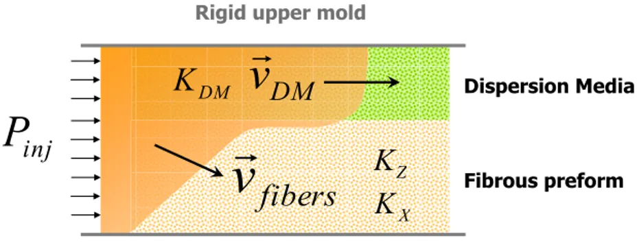
The impregnation of a porous preform by a liquid resin can be modelling as a transient Darcy’s flow (1). In the case of the DM-RTM process, a highly permeable dispersion medium is added above the fibrous preform to facilitate resin impregnation of the laminate (see Fig.4).
LRI dispersion media Preform carbon
Membrane
Resin
Figure 4 : Flow description in DM-RTM process.
Important differences between permeability of dispersion media and laminate (more than 1,000 times) induce a complex 3-dimensional resin flow. Due to the higher permeability of the dispersion medium, resin initially flows through it forcing a though-thickness impregnation of the low permeability laminate.
A new numerical solution has been developed by EADS IW in collaboration with Ecole Polytechnique of Montréal [2]. The simulation module is based on a Darcy’s law evolution. In this case, the flow in the fibrous preform is expressed by equation (3).
(3)
Where, v is the average superficial fluid velocity, P is the pressure gradient between two adjacent cells, named + and – in the equation, [K] is the permeability tensor of the porous medium and μ the resin viscosity.
Some application cases were carried out on composite parts and allowed us to confirm the advantages of the proposed numerical simulation on a real aeronautical part.
An example of application consists in a fuselage panel, auto-stiffened panel of 3,5 x 3 meters, with a ratio between length and thickness higher than 1000 (see Fig. 5).
fibers
v
DMv
injP
Dispersion Media Fibrous preform DMK
XK
ZK
Rigid upper mold
Rigid lower mold
ˆ ˆ 2 fib fib Z Z Z X X fib K P P K P v x z x z
K
P P
KZ
PZ PZ
KZZ
PZZ PZZ
KZ
PZ PZ
K
P P
KZ
PZ PZ
KZZ
PZZ PZZ
KZ
PZ PZ
K
P P
K
P P
K
P P
K
P P
fib fib X X Kfib Pfib Kfib Pfib X X KX PX v XX XX Figure 5 : EADS Innovation Works composite fuselage panel (Barrel test, TANGO Fuselage program).
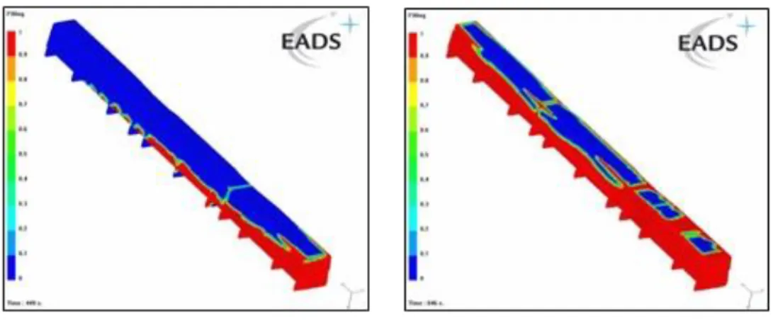
A preliminary study showed the difficulties to reproduce the different flows of this kind of process with standard numerical solution. The comparison between the average K solution and the DM-RTM solution developed showed us benefits of the average K solution (see Figure 6).
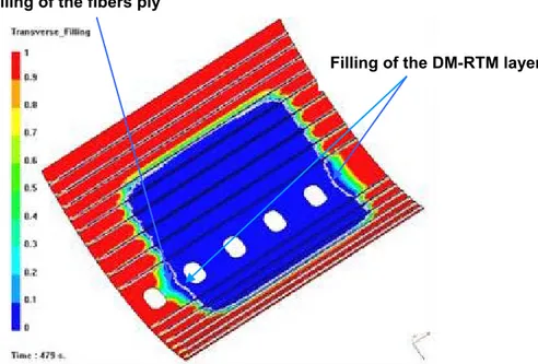
With this new numerical solution, we can evaluate the transverse flow through the preform and the in-plane flow in the DM-RTM (see Figure 7) with a meshing constituted of shell element (easier to set up than tetra element meshing).
Figure 6. Comparison between the average solution and the developed DM-RTM solution.
PERMEABILITY MEASUREMENTS : RECENT ADVANCES
The development and optimization of these technologies as well as the associated numerical simulation require knowledge of physical properties of the fibrous material, called preform. The resistance to the resin flow is defined by the permeability tensor of the preform in the model of Darcy’s law. Considering the industrial different LCM processes and the targeted fiber content of aeronautical composite parts, a complete identification of the permeability tensor is necessary.
Characterization of an adequate permeability value is still on debate: saturated or unsaturated method, accuracy of identification protocol, dual scale flow issues… Furthermore, industrial context force to require the characterizations procedures to be reliable, reproducible and realistic. Moreover, LCM technologies used by EADS Business Units, change in function of targeted part (geometry, thickness, fiber content...) and so induce various flows during the injection stage. In this aim in view, different protocols of permeability measurements have been set up for several years by EADS Innovation works in collaboration with academic partners, in order to be close to our requirements. For each method, we describe the selected protocol, the reasons of the choice and some illustrations of their targeted applications on industrial composite structures.
A reference method of in-plane permeability measurement has been developed in collaboration with Ecole Polytechnique of Montréal. The main advantage consists in a standard measurement procedure of in-plane unidirectional permeability with fully automated instrumentation (see Fig. 8). This concurrent method includes a built-in correlation with Darcy’s law and allows an estimation of experimental and numerical errors.
Filling of the DM-RTM layer Filling of the fibers ply
Fig. 8 View of global measurement system of the in-plane permeability bench.
The displacement of a newtonian fluid through a porous medium can be predicted by the Darcy’s law (1).
In the unidirectional case, we can write:
P L V K i .. (4)
with Vi, instantaneous velocity of flow, and
P L
is the linear pressure drop.
The principle of the measurement consists in using Darcy’s law in order to calculate the permeability value. Also, we must:
• follow during the infiltration, the flow front through the fibrous medium, • measure the pressure gradient present in the reinforcements.
The developed protocol takes into account these principles by integration of: • optical fibers in order to detect the resin position,
• pressure sensors in order to measure the pressure gradient,
• temperature sensors inside the mold cavity in order to calculate the fluid viscosity, • automatic treatment of measured data in order to estimate the permeability value • GUI (see Fig. 9) in order to follow in real time on a screen the flow front evolution
and parameters process (pressure injection as a function of time, for example),
• report obtained by computer including results sheet (permeability value, uncertainty) and other recorded information during tests.
Three different methods have been developed in order to process data of tests and give three different estimations of permeability value [3].
The unidirectional method in opposition of the radial flows method has been selected. The last approach is attractive for non isotropic permeability materials (fabrics for example) because the two principal permeabilities could possibly be evaluated in a single experiment. However, some difficulties have been shown [4] concerning the complex data acquisition of a central injection (record of an elliptic flow front with sensors, fit the experimental front position to a perfect ellipse) and the influence to the radius of the injection port during the identification of the permeability value (difficulties of comparison of the experimentally observed wetted areas with an analytical solution of Darcy equation in cylindrical coordinates).
The targeted processes by this permeability measurement protocol are the Resin Transfer Molding (RTM) process including rigid mold and process inducing constant fiber content during the injection. This family of LCM technologies represents the major part of the injected aeronautic composite parts manufactured for EADS products, in order to obtain data about the injectability of the preform.
A dedicated numerical approach has been developed in parallel of this protocol and allows having some information on the filling stage of the part [5].
From a few years, some through-thickness permeability measurements have been developed [6-7]. EADS France IW proposes in collaboration with the University of Le Havre a new continuous saturated through-thickness permeability (see Fig 10).
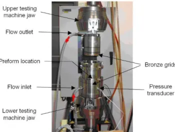
Fig. 10 View of global measurement system of the through-thickness permeability set up.
This apparatus consists of a cylindrical chamber within a guided piston which induces the exact fiber compaction in the transverse direction. The device is introduced into a universal testing machine to control the displacement of the piston and the force applied to the fibrous medium. The fluid is directed to the transverse direction by perforated bronze grids. A pressure transducer is placed below the lower grid. Test samples of fibrous preforms are placed between the two grids. Another device is placed on an other universal testing machine in order to apply a controlled flow rate of fluid on the fibrous reinforcement. When a newtonian test fluid is injected at a constant flow rate through the fibrous reinforcement, an evolution of pressure is measured by the pressure sensor. The transverse permeability Kz is calculated using Darcy’s law:
Q P A h KZ (5)
where μ is the dynamic viscosity of the test fluid, h and A are respectively the thickness and the area of the preform, Q is the imposed flow rate and P is the difference of pressure induced by the constant flow rate of test fluid through the reinforcement.
Finally, the through-thickness permeability is assessed in a continuous way according to fiber content through the controlled compression of the porous medium (see Fig 11).
Fig. 11 Example of results of through-thickness permeability method.
The obtained saturated permeability allows obtaining important information on through-thickness injectability of the preform. The targeted processes by this permeability measurement protocol are processes inducing non constant fiber content during the infusion. This family of LCM technologies represents a new part of the injected aeronautic composite parts manufactured for EADS products (large composite parts with high fiber content).
A dedicated numerical approach has been developed in parallel of this protocol and allows having some information on the filling stage of the composite part [8].
Finally, a permeability measurement specifically dedicated to process including double porous medium has been developed in relation with Ecole Polytechnique of Montréal. The infiltration of the fluid through different porous medium can be represented by different flows (see Fig 4).
Thanks to eq (1), these resin flows can be estimated by applying Darcy’s law with a pressure gradientPDM in the DM, Pfibers through the laminate:
t DM DM DM DM Q P A Q K and
fibers t fibers fibers fibers Q P A Q
K (6)where QDM is the flow rate through the dispersion medium, Qfibers the flow rate in the laminate, Q the flow rate between the dispersion medium and the laminate, A the in-plane t
area, is the dynamic viscosity of the test fluid, fibers , Dm and
Kfibers
,
KDM
,respectively the fiber content and the permeability tensor of the laminate and the dispersion medium.
For thin laminates, the through-thickness flow Q can be estimated by applying Darcy’s law t
between the DM and the laminate:
) ( DM fibers fibers T fibers t P P A Q K (7) where T fibers
K is the transverse through-thickness permeability of the laminate, DM
P the
pressure in the dispersion medium, and fibers
P the pressure in the laminate.
One way conceivable to experimentally identify theses properties consists in the characterization of each properties separately: one measurement for DM (in-plane permeability) and two other for fibrous perform (in-plane and through thickness permeabilities).
Nevertheless, to obtain accurate thought-thickness permeability of a high fiber content preform and in-plane permeability of DM is still on debate. Secondly, an approach of separated measurement of the both porous medium don't allow taking into account the coupling between the in-plane permeability of DM and fiber content of the preform.
The developed method consists in maintaining the proposed measurement of permeability of first chapter but taking into account the intimate link between the porous media. So, the carried out method induces the characterization of the couple of material in the same measurement (see Fig 12).
Fig. 12 View of experimental test bench.
In the end, we obtain directly the necessary permeability values through only one flow filling of the double porous medium. A specific software has been developed in order to identify the permeability from experimental data (see Fig 13).
The targeted processes by this permeability measurement protocol are processes inducing infiltration of a double porous medium at constant fiber content like Liquid Resin Infusion process.
For these different methods, numerical solutions were developed in parallel and applied on industrial parts. This clearly demonstrated how these different tasks highly contribute to the integration of composite process simulation in the development of aeronautical structural composite parts.
OPEN ISSUES
Another recurrent important issue encountered in the modeling and simulation of LCM concerns the porosity prediction in the manufactured parts. Preforms exhibit two characteristic length scales, the finest one related to the distance between individual fibers integrating the yarn, and the coarse scale representing the distance between neighbor yarns. Thus, if the injection velocity is dominant with respect to capillary effects, the inter-yarns spaces are fulfilled before the yarn impregnation that results in micro-porosities within the yarn core. On the contrary when capillary effects are dominant a residual porosity is noticed at the mesoscopic scale (in between the yarns). Different models have been proposed concerning a single phase and also multi-phase models [9], however no model is at present able to predict quantitatively the experimental observations.
Another issue concerns the injection of reinforced resins involving micro or nano charges (e.g. carbon nanotubes). The use of this kind of additives is important in order to enhance the part properties, like thermal or electrical conductivity. However, at present the dispersion, rheology and filtration of charges when the suspension flows within the porous media need further developments. Moreover, Darcy’s flows don’t consider microscopuic details, and it is important to remember that the CNTs orientation (and the final properties strongly depend on the orientation distribution) is governed by the microscopic flow features. Certainly for describing orientation effects richer description than the averaged Darcy’s flow should be necessary, micro-macro simulations being a potential alternative.
Obviously, the control of porosity in manufactured parts and the use of nano-charges for improving the properties of structures are of major interest in many industrial applications.
CONTROL & OPTIMISATION
Control and optimization techniques require fast solvers able to anticipate filling defects, taking the appropriate actions to avoid them. The issue related to real time simulations is a fashionable topic in many branches of science and engineering. The use of high performance computing, parallel computing platforms … has made possible impressive simulations, but the deployment of resources is far of the availabilities of medium and small industries. Today, new tendencies concern the use of model reduction techniques that have been successfully applied in other contexts [10]. In the case of RTM, because the evolving geometry (the part of
the mould occupied by the fluid) the use of standard model reduction technique remains delicate.
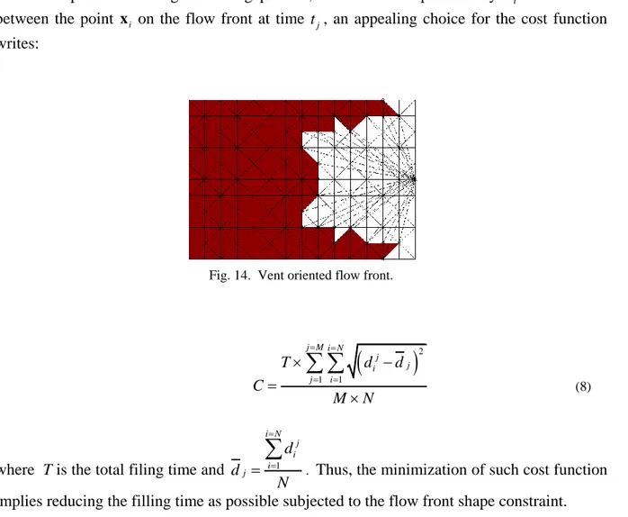
The second ingredient in control and optimization is the definition of a certain cost function that should be minimized. This function can integrate one or many criteria, and in all cases the choice depends on the process and the industrial requirements. For example if the main objective is to avoid dry zones in the mould (filling defect) one could try to define an injection protocol such that all the point defining the flow front at any time are at the same distance to the vent, as illustrated in Fig. 14. Ideally, if this condition is exactly fulfilled we ensure the perfect mould filling.
The idea is simple, but for computations we must describe this vent oriented flow front through a cost function. If we consider that the flow front at any time is described by
N points (that define a polygonal curve approaching the flow front), that we consider M flow front positions during the filling process, and that we represents by d the distance ij
between the point xi on the flow front at time t , an appealing choice for the cost function j
writes:
Fig. 14. Vent oriented flow front.
2 1 1 j M i N j j i j i T d d C M N
(8)where T is the total filing time and 1
i N j i i j d d N
. Thus, the minimization of such cost function implies reducing the filling time as possible subjected to the flow front shape constraint.Obviously, this choice is not unique, and many other choices exist. For example in reactive injection one could be also interested in minimizing the differences between the chemical contents of one point with respect to its neighborhood in order to maximize the homogeneity in the subsequent chemical reactions. The interested reader can refer to [11] and the references therein for a detailed analysis of this kind of strategies.
REFERENCES
[1] H. Darcy, “Les fontaines publiques de la ville de Dijon”, Dalmont, Paris, 1856. [2] E. Ruiz, S. Chatel, F. Trochu, “A simplified numerical approach to simulate resin transfer molding with a dispersion medium”, 8th International Conference on Flow Processes
in Composite Materials, page 331-340, July 2006.
[3] P. Ferland, D. Guittard, F. Trochu, “Concurrent Method for Permeability Measurement in Resin Transfer Molding”, Polymer Composites, Feb 1996, vol 17, pp 149-158.
[4] R. Gauvin, F. Trochu, Y. Lemenn, M.L Diallo, “Permeability Measurement and Flow Simulation through fiber Reinforcement”,Polymer Composites, 17(1), p. 34-42.
[5] F. Trochu, R. Gauvin, D-M. Gao, “Numerical Analysis of the Resin Transfer Molding Process by the Finite Element Method”, Advances in Polymer Technology, Vol. 12, no. 4, 1993, pp. 329.
[6] S. Comas-cardona, C. Binetry, P. Krawczak, “Unidirectional compression of fiber reinforcements, Part 2: A continuous permeability tensor measurement”, Composites Science
and Technology, Vol 67, March 2007, pp 638-645.
[7] S. Drapier, J. Monatte, O. Elbouazzaoui, P. Henrat, “Characterization of transient through-thickness permeabilities of Non Crimp New Concept (multiaxial fabrics)”,
Composites. Part A, Applied science and manufacturing , 2005, vol. 36, no7, pp. 877-892.
[8] T. Ouahbi, A. Saouab, J. Bréard, P. Ouagne, S. Chatel, “Modelling of Hydro-Mechanical Coupling in Infusion Processes”, Composite Part A, Applied science and
manufacturing, vol38, July 2007, pp 1646-1654.
[9] J.A. Garcia, Ll. Gascon, F. Chinesta, “A flux limiter strategy for solving the transport equations in RTM modeling void formation”, Composites Part A, In press.
[10] F. Chinesta, A. Ammar, E. Cueto, “On model reduction and its potential applications in chemical eginneering”, World Journal of Chemical Engineering (WJChE), 1/1, 3-12, (2007).
[11] F. Sánchez, Ll. Gascón, J.A. García, F. Chinesta, C. Zhang, Z. Liang, B. Wang, “A process performance index based on gate-distance and incubation time for the optimization of gate locations in liquid composites molding processes”, Composites Part A, 37/ 6, 903-912, (2006).